Cumhuriyet Üniversitesi Fen Fakültesi
Cumhuriyet University Faculty of Science
Fen Bilimleri Dergisi (CFD), Cilt:36, No: 3 Özel Sayı (2015)
Science Journal (CSJ), Vol. 36, No: 3 Special Issue (2015)
ISSN: 1300-1949
ISSN: 1300-1949
Modeling and Simulation of a 16/12 Double Stator Switched Reluctance Motor M. ASGAR1,*, E. AFJEİ1, M. M. MAHMOODİ2, A. R. BAHRAMİ3, M. A. FASİHİZADEH1 1Department 2Department 3Dep.
of Electrical Engineering, Shahid Beheshti University, G.C., Tehran, Iran.
of Electrical Engineering, Saveh Branch, Islamic Azad University, Saveh, Iran.
of Electrical Engineering, Isfahan (Khorasgan) branch, Islamic Azad University, Isfahan, Iran
Received: 01.02.2015; Accepted: 05.05.2015 ______________________________________________________________________________________________
Abstract. Modeling of a switched reluctance motor (SRM) is to predict the motor performance with a reasonable estimate over a wide range of speed and torque. Obtaining the realistic model of SRM which operates in a region of magnetic saturation due to complex structural implementation progress is too complicated process, with long response time. This paper introduces a linear model of double-stator SRM (DSSRM) which will be applied on directdrive washing machine application. The proposed method uses a developed simple magnetic equivalent circuit for modeling a DSSRM. The electromagnetic characteristics of the designed DSSRM are analyzed by finite element method (FEM) to validate the extracted results of the model. Finally, the experimental results with appropriate accuracy are achieved for modeling and magnetic analysis of the evaluated DSSRM. Keywords: Inductance profile, flux linkage, linear model, double-stator switched reluctance motors, finite element analysis
1.
INTRODUCTION
Nowadays, SRMs have been used for a wide range of various applications such as aerospace industry, marine propulsion systems, linear drives, mining drives, handheld tools, home utilities, etc. [1, 2]. The main reasons for using SRMs in these applications are low-cost construction characterized by an absence of magnets and rotor winding, fault tolerant power stage design and high level of performance over a wide range of speeds [3-5]. Reasonable cost and availability of the necessary electronic components make SRM as a viable alternative to other commonly used motors like induction machines, brushless DC (BLDC), permanent magnet (PM) synchronous or universal motors for various applications [6]. Despite all the advantages, in comparison with the PM or BLDC motors, the torque per volume or the efficiency of the SRM is not comparable [7]. Performance improvement of SRM is one of the interesting research topics to make it an applicable option to replace the PM or BLDC motor [8-11]. Different techniques have been used to enhance the efficiency of the SRM. Each method has its own advantages and disadvantages. Efficiency improvement in some methods is negligible, but some others can establish a significant improvement in efficiency [12]. Utilizing the segmented rotor and the double stator configurations are two effective approaches to improve the efficiency of the SRM.
_____________
*Corresponding author. Email address:
[email protected] Special Issue: The Second National Conference on Applied Research in Science and Technology http://dergi.cumhuriyet.edu.tr/cumuscij ©2015 Faculty of Science, Cumhuriyet University
ASGAR, AFJEİ, MAHMOODİ, BAHRAMİ, FASİHİZADEH
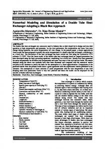
1.1 SEGMENTED ROTOR SRM The rotor structure of segmented rotor SRM (SSRM) composes of a series of discrete segments of laminated that are located on an aluminum or non-ferromagnetic cage. Therefore, each rotor segment is magnetically isolated from its adjacent segments. By replacing the conventional toothed rotor with individual segments, it has been verified that the higher torque density than the conventional SRM could be achieved [13]. In rotary SRM classification, depending on the total structure of SSRM, the rotor collection can rotate interior, exterior, or even middle of the machine structure. The stator structure of an SSRM is the same as conventional SRMs. The SSRM significantly improves the efficiency by eliminating the yoke on the rotor structure. This leads the rotor weight reduction, and makes shorter flux paths for the magnetic fields to reduce the current required and the number of phase winding turns. Moreover, decreasing the length of the flux path reduces the eccentric forces between the stator and rotor poles. The weak points of SSRM are related to the strength of segmented rotor holders, especially in high speeds, high temperatures, or in intense temperature variations applications. 1.2 DOUBLE STATOR SRM The components of the normal force that affect the performance of the linear SRMs are substantial. The DSSRM has enough ability to use appropriate radial force components in opposite direction in order to develop the motor performance to an acceptable level without experiencing any radial forces. The DSSRM structure composes of two opposing stators and a back-to-back rotor which is placed between the two stators. Structure of the rotor consists of either a yoke or discrete segments. Two opposite stators and the air gaps can create balanced radial force components on the rotor to produce high power density [14]. In DSSRM, the tangential force density related to the radial force is greater than the conventional SRM. It is worth mention that, the produced torque in this motor is directly dependent on the tangential force while the radial force does not help in torque production mechanism. The components of radial and tangential forces in segmented DSSRM are illustrated in Figure 1. Outer Stator
Motion Direction FR-O
FT-I FT-O
FR-I
Roto
r
Inner Stator Shaft Figure 1. The components of radial (FR-O-FR-I) and tangential (FT-O+FT-I) forces in segmented DSSRM.
It is noted that, the radial force components of outer (FR-O) and inner (FR-I) stators in DSSRM structure are in the opposite directions. Whereas, the tangential force components of the both inner and outer stators are in the same direction. Therefore, they added up.
2098
Modeling and Simulation of a 16/12 Double Stator Switched Reluctance Motor
In general, structure of DSSRM with approximate radial forces balanced will achieve a higher propulsion force, lower acoustic noise, and vibrations. Furthermore, the DSSRM with segmented rotor increases the torque per volume of the motor via decreasing the rotor weight. Therefore, the radial balanced forces and the segmented rotor of DSSRM are two key points which make the DSSRM as a suitable candidate for the most cost-effective alternative motors. In contrast, The DSSRM possesses some drawbacks. High torque density of the DSSRM also creates negative consequences. The high torque pulsation of the DSSRM is a negative point which caused by interaction between central rotor and changing reluctance of the two inner and outer stators. Furthermore, two stators with different bore diameters will produce asymmetrical forces on the rotor. In this paper, the DSSRM is studied using its approximate magnetic equivalent circuit. The parameters of the circuit are obtained by using a linear model of DSSRM. The mutual inductance between the phases winding are neglected related to simplicity. This paper is organized as follows: Section 2 presents the characteristics of the DSSRM. The principles of modeling have been discussed in Section 3. In Section 4 the reluctance equivalent circuit with proper equations has been analyzed. In Section 5 the DSSRM geometrics are detailed and listed. The results of the linear modeling are depicted in Section 6. The electromagnetic analysis has been performed in three-dimensional environment utilizing 3D-FEM by Magnet CAD package [15], in Section 7. Finally, conclusion remarks are summarized in Section 8. 2.
CHARACTERISTICS OF THE DSSRM
In addition to physical characteristics, electrical characteristics of the SRMs are influenced by the type of application [16]. One of the important electrical parameters in SRMs is the number of phases [17]. The investigated DSSRM with two stators (inner and outer) and segmented rotor is constructed from laminated silicon steel of soft magnetic material (M27). The rotor segments are fixed on an aluminum plate with multidirectional locking screws to increase the angular stability and resistance to fatigue, stress and cracking. This unique homogeneous structure makes the rotor configuration ideal for high speed, high temperature, harsh environments and servo applications. In addition, as was explained in Section I, avoiding any non-metallic material in the rotor will not only make the motor more sturdy but will also guarantee a more streamlined manufacturing process. 3. PRINCIPLE OF MODELING The significant inductance profile changes are determined in terms of the both stators and rotor arcs and the number of rotor poles. As seen in Figure. 2, inductance profile can be divided into five sections. Each of these five defined inductance regions due to aligned and unaligned of the rotor and stators poles are contributed positive 1 ~ 2 , negative 3 ~ 4 torque or do not provides any torque production 0 ~ 1 ,2 ~ 3 ,4 ~ 5 .
2099
ASGAR, AFJEİ, MAHMOODİ, BAHRAMİ, FASİHİZADEH
s
Ou Sta ter tor
d te en r gm to Se Ro
0
1
2
3
4
er Inn tor Sta
5
r
y
B Shaft
x
Figure 2. Cross section of view of a 16 by 12 four-phase segmented rotor DSSRM.
As shown in Figure 3, the inductance profile changes are dependent on the rotor, two inner and outer stators and the number of rotor poles. In the following equations the rotor pole arc is assumed to be greater than the stators arc. The various angles are calculated as follows:
1
1 2 s r 2 Nr
(1) 2 1 s
(2) 3 2 r s (3) 4 3 s (4) 5 1 4
2 Nr
(5)
Where N r is the number of rotor poles, r and s are rotor and stators pole arcs. In most cases: r s , but if: r s , the interval between 2 and 3 is eliminated. Thereby, the equations (1) and (2) will be amended as follows: In this regard, from Figure 2, the various angles are obtained as: Nr
1
r
,
2 Nr
(6)
4. MAGNETIC EQUIVALENT CIRCUIT OF DSSRM
The obtained magnetic elementary equivalent circuit which is related to the flux path of a three-phase 16 by 12 pole DSSRM in aligned position (θ2 ≤ θ ≤ θ3) is shown in Figure 3. The symmetrical magnetic flux produces respect to the excited stators windings of phase A. The flux of B which is made in the inner and outer stators poles crosses through the stator poles, stator yokes, air gaps, rotor segments. As mentioned above, Due to the radial symmetry, only a quarter of stator poles of a phase, and two of the four corresponding segments were modeled. The reluctances of inner stator pole, inner stator yoke, outer stator pole, outer stator yoke, air gap, rotor segments for the flux path are symbolized as insp , insy , outsp , outsy , gap, and rs , respectively. The simplified magnetic equivalent circuit for flux of B in terms of the reluctances, inner and outer stators magneto-motive forces (MMFs), Fin and Fout, is depicted in Figure 4.
2100
Modeling and Simulation of a 16/12 Double Stator Switched Reluctance Motor
out sp
B
Fin
gap
rs
B
gap
Fout in sp
out sy
in sy out sp Fin
B
gap
rs
gap
Fout
B
in sp
Figure 3. Simplified Magnetic equivalent circuit of DSSRM in aligned position.
To start analysis of the magnetic circuit, the values of the total reluctance ( m ) and MMF (F) must be determined. Therefore, the total MMF for Phase A is calculated as follows: (7) F 2Fin Fout In DSSRM, total reluctance is related to the various angle of back-to-back segmented rotor. Total reluctance of the equivalent circuit in Figure 3, is obtained by: m 2out sp 2gap rs in sp out sy in sy
(8)
The effects of mutual inductance, flux linkage and magnetic potential are neglected in the linear magnetic equivalent circuit. Considering the permeability of the medium equation in the movements of the flux linkage, the total reluctance in Equation (8) is expanded to: lout sp 2l gap lin sp l rs m 2 A 0 r Ain sp 0 r out sp 0 Agap 0 r Ars
lout sy lin sy A 0 r Ainsy 0 r out sy
(9)
In Equation (9), 0 and r are air gap and relative magnetic permeability. The length (and area) of outer stator pole, air gap, rotor segment, inner stator pole, outer stator yoke, inner stator yoke are symbolized as l Aout sp , l Agap, l Ars , l Ain sp , l Aout sy , and l Ain sy , respectively. After calculating the total reluctance, inductance of the DSSRM can be obtained from the following equation: L
2 N ph
(10)
m
Where N ph is the number of phase winding. Finding of the minimum (Lu) and maximum (La) inductances in SRMs is related to the flux path. Maximum inductance predicts from fully aligned position and minimum inductance predicts in the farthest angle at unaligned position. Inductances between Lu and La can be calculated from two or three dimensional finite element analysis (FEM). 5. DSSRM GEOMETRICS
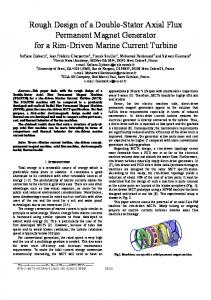
The 16/12 evaluated DSSRM has a four-phase configuration with dual sets comprising of stators and one back-to-back rotor with 16 by 12 poles. Figure 4 shows the three dimensional schematic view of a 16/12 DSSRM. In this configuration, there are 32 coils which each 8 set of coils composes a phase. The torque produces inside the gaps between segmented rotor and the inner and outer stators. In 16/12 DSSRM, there are 8 symmetrical air gaps per each phase. The resultant normal forces are closed to zero. Therefore, due to the equality of the tangential forces
2101
ASGAR, AFJEİ, MAHMOODİ, BAHRAMİ, FASİHİZADEH
and motional forces, the performance of the motor increases as well. To prove this fact, the multipart three dimensional paths of the DSSRM require a three-dimensional analysis.
Figure 4. Three dimensional schematic view of a 16/12 DSSRM.
The input parameters of the motor which are utilizing in analytical and numerical analyzes are listed and detailed in TABLE 1. The motor dimensions and electrical parameters can be used to find the magnetic equivalent circuit components and to employ in the FEM analysis. Table 1. Dimensions and electrical parameters of the evaluated 16/12 DSSRM.
Parameter Ns Nr q D D0 Di L βs WR WS Nph La Lu Ncoil
Definition Number of stator slots Number of segmental rotors Phase number Outer diameter of the motor Outer stator inside diameter Inner stator outside diameter Stack length Stator pole arc Segmental rotor width Stator tooth width Number of phase winding Inductance in aligned position Inductance in unaligned position Number of series coils per phase
Value 16(dual) 12 4 260 [mm] 200 [mm] 140 [mm] 40 [mm] 7.5[Deg.] 15 [mm] 15 [mm] 75[Turn] 14 [mH] 59 [mH] 8
6. RESULTS OF THE MODELING For modeling of DSSRM, in the first step, the L of phase A must be defined. The value of phase inductance can be displaced by an angle which is given by: 1 1 N N s r
(11)
2
2102
Modeling and Simulation of a 16/12 Double Stator Switched Reluctance Motor
60
LMax
Inductance [mH]
50
40 30
2
20
Lmin
10
1
0 -20
-15
-10
-5
0
5
10
15
20
Rotor Angle [Deg.]
Figure 5. Linear inductance profile of phase A.
From equation (6) the 1 and 2 which are indicated in Figure (5) can be calculated. Considering to flux linkage and phase current, the minimum and maximum inductance (Lmin and Lmax) which are related to the flux path are obtained in the linear model. At the middle rotor angles, from the overlapping states, the inductance of phase is predicted from a linear magnetic analysis. 30
Current [A]
25 20 15 10 5
0 0
2.5
5
7.5
10
12.5
15
17.5
20
22.5
25
Time [ms]
Figure 6. Current of Phase A from linear model of DSSRM.
In Figure 6, the excitation current of phase A during the rotor movement from unaligned to aligned positions in linear model of DSSRM is illustrated. At unaligned position, due to the minimum inductance, the variations of the current is faster than near to the aligned position. According to the rotor position and inductance profile along to the phase current in linear model of DSSRM, the produced torque in phase A is illustrated in Figure 7.
2103
ASGAR, AFJEİ, MAHMOODİ, BAHRAMİ, FASİHİZADEH
1.2 1
Torque [N.m]
0.8 0.6
0.4 0.2
0 0 -0.2
5
10
15
20
25
Time [ms]
Figure 7. Linear produced torque from excitation of phase A.
7. ELECTROMAGNETICS MODELING AND ANALYSIS
The performances of the magnetic equivalent circuit can be validated via FEM analysis. The FEM is a useful tool to provide a complete analysis of the SRM, because it has ability to model non-linear magnetic properties as well as static and dynamic studies. Nevertheless, the relevance of DSSRM output variables to its dimensions are not definitive. Therefore, an adjustment of any device parameters demands new computational analysis by FEM. The flux distribution at fully aligned and unaligned positions in the stator and rotor poles under 8A phase excitation current is obtained and shown in Figure 8(a, b). In this structure, the maximum flux density on the surface of stator and rotor cores is about 1.32 [Tesla]. As can be seen, through the adjacent stator poles, the flux vectors of the stator poles are spreading outward into the stator yoke. (a)
(b)
Figure 8. Magnetic flux distribution in stator and rotor poles in (a) aligned, and (b) unaligned positions.
About at ±11o, the rotor position is in unaligned point, which the flux value of the rotor and stator poles is in minimum amplitude. In this situation, the rotor poles have a little overlap with
2104
Modeling and Simulation of a 16/12 Double Stator Switched Reluctance Motor
two groups of the stator poles. One of them can move the rotor to the clockwise and the other one to the counter-clockwise position. The flux-linkage of the DSSRM is a function of stator current and rotor position. Figure. 9, shows the simulation results of the motor flux-linkage from unaligned to unaligned positions. Individually, the flux-linkage with respect to the rotor angle and the constant excitation current has a Gaussian distribution shape that the flux-linkage falls off towards zero quickly. Also, in the aligned position (0o) the flux-linkage for all the currents is at its maximum value. By increasing the current, flux-linkage curves, due to approaching the saturation region, are closer to each other. In regions near to unaligned positions, the values of the flux-linkage are almost unchanged because of constant inductance and the air gap.
Figure 9. The flux-linkage vs. rotor position in various stator currents.
For precise flux evaluation, the shape of flux linkage in aligned and unaligned positions for various stator currents is illustrated in Figure 10. As shown in this figure, flux linkage in aligned position is 4.82, 4.81, 4.80, 4.16 and 3.83 times higher than unaligned position for 2, 8, 12, 18 and 20 Ampere current, respectively. This feature proves the ability of produced torque in the designed motor.
Figure 10. The flux linkage of each coil in aligned and unaligned positions vs. stator currents.
2105
ASGAR, AFJEİ, MAHMOODİ, BAHRAMİ, FASİHİZADEH
Figure 11 shows the stored magnet energy variations from unaligned to aligned positions in a wide range of excitation currents. The minimum values of the stored energy are in the unaligned positions and the maximum of the stored energy is in aligned position. The interval between minimum and maximum values of the stored magnetic energy have been changed nonlinearly, which this deferential value of energy helps to produce more torque.
Figure 11. The inductance variation from unaligned to aligned positions.
The torque produced by a DSSRM is a function of the rotor movement and stator current. Figure 12 shows the positive and negative torques from unaligned to aligned positions in various currents. As depicted in Figure 12, in all current levels, the produced torque around the aligned position (0o) is zero. The maximum motor torque is increased from 0.086 to 0.126, 0.175, 0.238, 0.318 and 0.415 [N.m] when stator current rises from 10 to 12, 14, 16, 18 and 20 [A], respectively. The obtained shape of DSSRM torque is the same as other conventional SRMs, that torque will be controllable in different conditions.
Figure 12. The torque vs. rotor position for various stator currents.
8.
CONCLUSIONS
This paper presents a developed linear model of a 16 by 12, four-phase DSSRM used for direct-drive application. For this purpose, an equivalent circuit is introduced to predict the performance of the DSSRM. In this regard, the motor equations were used to describe the
2106
Modeling and Simulation of a 16/12 Double Stator Switched Reluctance Motor
design procedure step by step. Then motor was modeled by FEM and the flux distribution, flux linkage, stored magnetic energy, and torque profiles are obtained and analyzed. The flux linkage in aligned position was about 530, 630, 700, 760, 810 and 840 [mWb] for 10, 12, 14, 16, 18 and 20 [A] currents, respectively. Besides, the deferential value of unaligned and aligned flux linkages proves the proper designed motor with acceptable torque production. It has the ability of becoming the motor potentially can be used for direct-drive application. REFERENCES [1]
[2]
[3]
[4]
[5]
[6]
[7]
[8]
[9]
[10] [11]
[12]
[13]
Da-Woon, C.; Sang-In, B. and Yun-Hyun, C. (2014), “A Study on the Maximum Power Control Method of Switched Reluctance Generator for Wind Turbine,” IEEE Trans. on Magnetics, vol. 50, no. 1, pp. 1-4. Labak, A. and Kar, N. C. (2013), “Designing and Prototyping a Novel Five-Phase Pancake-Shaped Axial-Flux SRM for Electric Vehicle Application Through Dynamic FEA Incorporating Flux-Tube Modeling,” IEEE Transactions on Industry Applications, vol. 49, issue 3, pp. 1276–1288. Zhang, H.; Xu, W. Wang, S. et al. (2014), “Optimum Design of Rotor for High-Speed Switched Reluctance Motor Using Level Set Method,” IEEE Transactions on Magnetics, under publication vol. 50, issue 2. Murray, A.; Palma, M. and Husain, A. (2008), “Performance Comparison of Permanent Magnet Synchronous Motors and Controlled Induction Motors in Washing Machine Applications Using Sensorless Field Oriented Control,” IEEE on Industry Applications Society Annual Meeting (IAS'08), pp. 1-6. Rallabandi, V. and Fernandes, B. G. (2014), “Design procedure of Segmented Rotor Switched Reluctance Motor for Direct Drive Applications,” IET Electric Power Applications, vol. 8, issue 3, pp. 1-6. Mazlan, M. M. A.; Sulaiman, E. and Kosaka, T. (2014), “Design Study of Single Phase Outer-Rotor Hybrid Excitation Flux Switching Motor for Hybrid Electric Vehicles,” IEEE Conference on Power Engineering and Optimization (PEOCO), pp. 138-143. Keshri, R.; Garlapati, S.; Tessarolo, A. and Buja, G. (2014), “Torque Capabilities of a Five-Phase PM BLDC Drive vs. a Three-Phase one and Various Supply Modes,” IEEE International Conference on Electric Vehicle (IEVC), pp. 1-8. Torkaman, H.; Afjei, E. and Toulabi, M. S. (2012), “New Double-Layer-per-Phase Isolated Switched Reluctance Motor: Concept, Numerical Analysis, and Experimental Confirmation,” IEEE Transactions on Industrial Electronics, vol. 59, no. 2, pp. 830-838. Jun, C.; Zhiquan, D. and Rongguang, H. (2014), “Position Signal Faults Diagnosis and Control for Switched Reluctance Motor,” IEEE Transactions on Magnetics, vol. 50, no. 9, pp. 1-11. Peter Balazovic and Roman Filka, (2011), “Sensorless PMSM Control for an H-axis Washing Machine Drive," Freescale Semiconductor. Mosallanejad, A. (2014), “Analyses of the Effect of Length Difference between Plunger and Winding on Tubular Linear Reluctance Motor Performance,” International Transactions on Electrical Energy Systems, pp. n/a-n/a, DOI: 10.1002/etep. Yu, Q. and Gerling, D. (2013), “Analytical Modeling of a Canned Switched Reluctance Machine with Multilayer Structure,” IEEE Transactions on Magnetics, vol. 49, no. 9, pp. 5069-5082. Vandana, R. and Fernandes, B. G. (2014), “Design Methodology for High-Performance Segmented Rotor Switched Reluctance Motors,” IEEE Transactions on Energy Conversion, vol. 30, issue: 1, pp. 11-21.
2107
ASGAR, AFJEİ, MAHMOODİ, BAHRAMİ, FASİHİZADEH
[14] Isfahani, A. H. and Fahimi, B. (2014), “Comparison of Mechanical Vibration between a Double-Stator Switched Reluctance Machine and a Conventional Switched Reluctance Machine,” IEEE Transactions on Magnetics, vol. 50, no. 2, pp. 293-296. [15] MagNet CAD Package, (2006), “Design and Analysis Software for Electromagnetics," ed: Infolytica. [16] Tokita, T.; Goto, H. and Ichinokura, O. (2014), “An Effect of Electromagnetic Force on Acoustic Noise of Axial-Gap In-Wheel SR Motor,” International Conference on Electrical Machines (ICEM), pp. 987-993. [17] Ilhem, B.; Amar, B.; Lebaroud, A. and Fares, R. (2014), “Automatic fault diagnosis of fault tolerant power converter for switched reluctance motor based on time-frequency technique,” 16th international Conference and Exposition on, pp. 1234-1240.
2108