Mechanics and Mechanical Engineering Vol. 10, No 1 (2006) 74–81 c Technical University of Lodz °
Modeling and tracking control of wheeled mobile robots
J´ ozef Giergiel, Maciej T. Trojnacki Department of Applied Mechanics and Robotics, Rzeszow University of Technology
[email protected],
[email protected] Received (15 May 2006) Revised (29 May 2006) Accepted (17 June 2006)
The problem of tracking control of wheeled mobile robots (WMRs) using neural network is analyzed in this paper. The synthesis of control systems using the second Lapunov method was carried out. As a result of the synthesis, the stability of the designed systems was proven. A large number of computer simulations for these control systems using Matlab/Simulink package were executed. The results of the theoretical tests were verified by the rapid prototypical method. The rapid prototyping environment for the Pioneer robot was based on the Matlab/Simulink package and dSPACE board. Keywords: Wheeled mobile robot, modeling, tracking control, Lapunov method, neural network, rapid prototyping
1.
Introduction
Wheeled mobile robots (WMRs) are vehicles which move along desired trajectories. This kind of motion of WMRs is called follow-up motion. The desired trajectories are usually in the form of high frequency inductive wires or reflective tapes, which are placed into pavement. These trajectories can also be set into WMRs’ microcomputers memories. The tracking control of robots is usually carried out using PID control. This type of control characterizes system sensitivity to variable work conditions [1,2,3,4,5]. In this study the problem of tracking control of WMRs is taken into consideration. The control algorithm uses the artificial neural network; therefore, it can adapt to variable work conditions. 2.
Modeling of Nonholonomical Systems
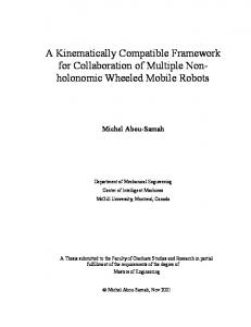
The wheeled mobile robot model, which is shown in the Fig. 1, contains 4 components: driving wheels 1 and 2, caster 3 and frame 4 [1]. The dynamics of the 2-wheeled mobile robot is described using Maggi’s equations, which can be written
Modeling and tracking control...
75
in matrix form as follows [1,5] M (q, a)¨ q + C(q, q, ˙ a)q˙ + F (q, ˙ a) = u
(1)
where q is a vector of generalised coordinates, M (q, a) is a matrix of robot inertia, C(q, q, ˙ a) is a vector of centrifugal and Coriolis’s forces, F (q, ˙ a) is a vector of friction forces and u is a vector of control signals.
Figure 1 Wheeled mobile robot Pioneer 2DX and its model
3.
Designing of Neural Control Systems
Within the confines of this work, the synthesis of neural control system for 2-wheeled mobile robot was performed. This control system was designed in order to realize tracking control for the selected point of this robot i.e. H (see Fig. 1). This point moves along the desired trajectory qd (t) such that both the signals qd (t), q˙d (t) and q¨d (t) are limited and the equation of nonholonomical constraints J (qd ) q˙d = 0 comes true. This system is also observable. The synthesis of neural control system was realized using the second Lapunov method. For this method the positively defined function [1,2,4] was assumed as: ³ ´i 1h T ˜ T F −1 W ˜ V (t) = s M (q)s + tr W (2) 2 ˜ =W −W ˆ , s = q˙ − v, v = q˙d − Λqe , qe = qd − q, where the following hold true: W ˆ ˜ [W – estimated neural network weights, W – error of estimated weights, s – generalised tracking error, v – supporting signal, qe – tracking error]. As a result of this synthesis the control signal was assumed as follows: ˆ T S(x) + KD s u=W
(3)
and weights learning law given by ˆ˙ (t) = F S (x) sT , W
(4)
where: F is a matrix of gains, S(x) is a vector of neural transfer functions. In order to assure stability of the considered system, the propel value of the gain KD has to be selected. It was executed during simulation research. The neural
76
Giergiel J. and Trojnacki M.
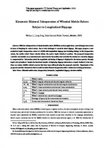
control system was realized based on radial neural network with Gauss’s functions (see Fig. 2). The input vector was defined as £ ¤T x = v1 v2 v˙ 1 v˙ 2 α˙ 1 α˙ 2 . (5) Usually modeling multi-input system multidimensional radial basis functions (RBFs) are applied. These functions [1,2,5] are given by à ! 2 kx − ck S (x, c) = exp − (6) 2δ 2 where: x represents the input vector, c signifies the vector of centers coordinates, and δ is the variance vector along individual axes of variables xi , i = 1, 2..6. The neural network output vector has the following form y = W T S(x)
(7)
Figure 2 Neural networks with radial basis functions
4.
Simulation Results
Simulation research using Matlab package was carried out. Quality rates were used to compare individual control algorithms. These rates are • an integral of the square of tracking error ZT qe2 dt
E=
(8)
0
• maximum of absolute tracking error qe max = max (|qe |). t∈T
(9)
(9)
Before starting the simulations, a desired motion path and motion parameters for wheeled mobile robot Pioneer 2DX was assumed. These are shown in Fig. 3.
Modeling and tracking control...
77
During simulation research the resistance of the control system to parametric disturbances was tested. The diagram of the neural control system is shown in Fig. 4. For the simulations the parameters below were assumed · ¸ · ¸ 0.6 0 2 0 F = ηI, Λ = , KD = . 0 0.6 0 2 Simulation 1 Within the first simulation the resistance of the control system to parametric disturbances was tested. For time t = (6, 8) [s] robot drives over different type of road surface. Different types of road surfaces produce different values of friction factors while simulation. This simulation was executed with four radial neurons and coefficient η = 3. The results of simulation are shown in Fig. 5 and 6. a)
b)
c) .
vA [rad/s]
?1? [rad/s]
6
0.4
.
?2? [rad/s] 0.3
4
0.2 2 0.1
t [s]
0
t [s]
0 0
0
5
10
15
20
5
10
15
20
25
25
Figure 3 Desired: motion path of point H (a), speed of point A (b) and velocities of wheels 1 and 2 (c) of mobile robot
Figure 4 The diagram of the neural control system for 2-wheeled mobile robot
Simulation 2 In order to assess the obtained results of the neural network controller, analogous simulation was executed using PD controller. The results of this simulation are demonstrated in Fig. 7. Considering the results of Simulations 1 and 2, one notices that Simulation 1 is superior. One can ensure which simulation is better first by comparing the quality rates (see Fig. 6b and 7c) as well as the tracking errors graphs (see Figure 5c and 7b). In Simulation 1 the quality rates are much lower; indicating a much preferable control system, reason being four radial neurons were used. This solution gives the
78
Giergiel J. and Trojnacki M. a) b)
c) M1 [Nm] M2 [Nm]
6
6
e1 [rad] e2 [rad]
0.4
uPD1 [Nm] uPD2 [Nm]
4
0.2
uNN1 [Nm]
4
uNN2 [Nm] 0 2
2 -0.2
0
0
-0.4
t [s] -2
t [s]
5
10
15
20
25
t [s]
-0.6
-2 0
0
5
10
15
20
0
25
5
10
15
20
25
Figure 5 Driving torques (a), compensating and PD control (b) and tracking errors (c) for neural control system
a)
b) 2
W1,1 W1,2 1.6 W1,3 W1,4 1.2
0.8
Wheel
E 0.2075 0.2096 0.2086
1 2
0.4
Medium
qemax 0.4574 0.4574 0.4574
0
t [s]
-0.4 0
5
10
15
20
25
Figure 6 Selected estimations of robot parameters (a) and obtained quantitative assess (b) for neural control system
a)
b) M1 [Nm] M2 [Nm]
5
c) e1 [rad] e2 [rad]
0.4
4
0
3
-0.4
2
-0.8
1
-1.2
Wheel
0
1 2 Medium
E 37.1057 37.1075 37.1066
qemax 1.7233 1.7200 1.7217
-1.6
t [s] -1
t [s]
-2 0
5
10
15
20
25
0
5
10
15
20
25
Figure 7 Driving torques (a), tracking errors (b) and obtained quantitative assess (c) for PD controller
robot control system resistance to the parametric disturbances and compensates for the nonlinear robot dynamics. What is more, it provides greater tracking control.
Modeling and tracking control...
5.
79
Experimental Results
The simulation results were verified by the rapid prototyping method on a real robot Pioneer 2DX. The experimental environment for this robot [1,3] was based on: • Matlab/Simulink package, • dSPACE hardware. a)
b)
Figure 8 Experimental environment diagram for Pioneer 2DX rapid prototyping (a) and ControlDesk 1.0 software for experiment managing (b)
The experimental environment diagram is shown in Fig. 8a. In this drawing PC is a host and consists ControlDesk 1.0 software to manage the experiment. ControlDesk software (Fig. 8b) visualizes and records the experimental results. Experiment 1 This experiment was realized with similar assumptions and conditions as Simulation 1. The experimental results are shown in Fig. 9 and 10. a)
b) M1 [Nm] M2 [Nm]
12
8
c)
12
u PD1 [Nm]
10
u PD2 [Nm]
8
u NN1 [Nm]
6
u NN2 [Nm]
e1 [rad] e2 [rad]
0.4
0.2
0 4 4 2
-0.2
0 0
-2
-0.4
-4
t [s]
-4 0
4
8
12
16
20
t [s]
-6
t [s]
-0.6 0
4
8
12
16
20
0
4
8
12
16
20
Figure 9 Driving torques (a), compensating and PD control (b) and tracking errors (c) for Pioneer 2DX robot with neural control system
Experiment 2 In order to compare experimental research for the neural control system, similarly
80
Giergiel J. and Trojnacki M. a)
b) 2.5
W1,1 W1,2 2 W1,3 W1,4
1.5
Wheel 1
1 2 Medium
0.5
E 0.2494 0.2804 0.2649
qemax 0.4996 0.5159 0.5078
0
t [s]
-0.5 0
4
8
12
16
20
Figure 10 Selected estimations of robot parameters (a) and obtained quality rates (b) for Pioneer 2DX robot with neural control system
as in the simulations, the comparable experiment was executed using PD controller. The experimental results are shown in Fig. 11. The experimental results for the wheeled mobile robot Pioneer 2DX verify simulation research. The results confirm the simulation conclusions; therefore, these results prove the neural control system is superior for tracking control than traditional controllers, such as the PD controller. a)
b) M1 [Nm] M2 [Nm]
12
c) e1 [rad] e2 [rad]
1
8
0
Wheel 1 2 Medium
4
-1 0
E 65.0628 97.1456 81.1042
qemax 2.2250 2.5768 2.4009
-2 -4
t [s]
-8 0
4
8
12
16
20
t [s]
-3 0
4
8
12
16
20
Figure 11 Driving torques (a), tracking errors (b) and obtained quantitative assess (c) for Pioneer 2DX robot with PD controller
6.
Conclusion and Future Research
Considering both the simulation and the experimental results one observes the following: • The precision of tracking control using the PD controller is inferior to the neural controller, which compensates for the nonlinear robot dynamics and is resistant to the parametric disturbances. • The worst tracking errors occurred during starting and stopping. • Errors whilst starting appear because the neural control algorithm initializes
Modeling and tracking control...
81
the adaptive process and does not yet compensate for the nonlinear robot dynamics. • Tracking errors whilst stopping result from the large desired trajectory change. • The neural control system is resistant to the nonparametric disturbance as it does not require the precise dynamic model of the mobile robot. • The neural control system compensates for the nonlinear robot dynamics excellently. Acknowledgements This work was realized within the confines of the grant 4 T07A 030 29. References ˙ W.: Modelowanie i sterowanie mobilnych [1] Giergiel M. J., Hendzel Z., Zylski robot´ ow koÃlowych, PWN, Warszawa (2002). ˙ [2] Giergiel J., Hendzel Z., Zylski W., Trojnacki M.: Zastosowanie metod sztucznej inteligencji w mechatronicznym projektowaniu mobilnych robot´ ow koÃlowych, Monografia, Wydawnictwo KRiDM AGH, Krak´ ow (2004). ˙ [3] Hendzel Z., Zylski W., JagieÃlowicz C., Trojnacki M.: Real-time adaptive tracking control of wheeled mobile robot, Proceedings of the International Carpathian Control Conference, Krynica, Poland, (2001), 126-132. [4] Spong M.W., Vidyasagar M.: Dynamika i sterowanie robot´ ow, WNT, Warszawa (1997). [5] Trojnacki M.: Sterowanie ruchem nad¸az˙ nym mobilnego robota koÃlowego z zastosowaniem sieci neuronowych – Rozprawa doktorska, PRz, Rzesz´ ow (2003).