Modeling and Validating Interaction Aspects in UML Jon Whittle
João Araújo
Dae-Kyoo Kim
QSS Group/NASA Ames Moffett Field CA 94110 +1 650 604 3589
Faculdade de Ciências e Tecnologia, Universidade Nova de Lisboa + 351-21-2948536
Colorado State University Fort Collins CO 80523 +1 970 491 2466
[email protected]
[email protected]
[email protected]
ABSTRACT There has been significant recent interest, within the AspectOriented Software Development (AOSD) community, in representing crosscutting concerns at various stages of the software lifecycle. However, most of these efforts have concentrated on the design and implementation phases. We focus in this paper on representing aspects during requirements modeling. In particular, we address the issue of how to model aspects as part of interaction modeling. To illustrate this, we describe how error-handling interactions can be modeled as aspects and how they can be composed with non aspectual interactions. Aspects are modeled as Interaction Pattern Specifications (IPSs) and are composed with non-aspectual interactions using instantiation. The composed collection of interactions can then be translated automatically into a set of state machines using an existing state machine synthesis algorithm. This set of state machines can be simulated thus providing early feedback to requirements engineers.
1. INTRODUCTION Requirements engineers must know how to deal with the changing and crosscutting nature of requirements. Having changing requirements implies that any approach used to elicit and specify them must provide mechanisms to address requirements change and its impact on other requirements in an efficient way. Furthermore, when requirements cut across other requirements, tangled representations of those requirements all over the requirements document may result. Consequently, the reaction to change is more difficult, as the impact of the change is more complicated to handle. That is why it is important to consider crosscutting requirements early in the software lifecycle. The best way to deal with crosscutting requirements is to separate them from other requirements and model them independently. This modularization avoids tangled representations in the requirements document, facilitating requirements evolution. On the other hand, if no attention is paid to how the cross-cutting requirements relate to other requirements, there is a danger that the nature of these interactions will only become clear during later stages of software development. If problems with these interactions are only discovered at this point, they will, in general, be costly to rectify. Hence, it is necessary, at the requirements stage, to have both a means of modeling cross-cutting concerns independently but also a means of composing cross-cutting concerns with other requirements in a way that will allow the entire set of requirements to be validated.
In this paper, we will focus on interaction-based requirements. Interactions show the behavior of several system components communicating towards a common goal. Interactions are a good way of modeling early requirements because they show global exchanges between system components without showing all the internal behavioral details of each component. This paper will show how to model interactions (with aspects) in a way that they can be immediately validated. Interactions will be modeled as UML sequence diagrams. Aspectual interactions – i.e., interactions that cross-cut other interactions – will be modeled as Interaction Pattern Specifications (IPSs). Error-handling will be used to illustrate the technique. The aspectual and non-aspectual interactions will be composed by instantiating the aspects. The resulting set of interactions will then be translated automatically into a set of UML state machines. These state machines can be executed thus providing a convenient and easy way for the interaction-based requirements to be validated. The overall approach was presented in [8] and is summarized in Figure 1. Our aim here is to validate those ideas with a new example, a car parking system, and a new aspect. The paper is organized as follows: Section 2 describes aspectual interactions; Section 3 shows the application of the approach to an example. Section 4 depicts how state machines are generated; Section 5 shows some related work; and, finally, Section 6 presents some conclusions and points directions to future work.
2. ASPECTUAL INTERACTIONS
Pattern Specifications (PSs) are introduced in [2] 1 as a way of formalizing the structural and behavioral features of a pattern. The notation for PSs is based on the Unified Modeling Language (UML). The abstract syntax of UML is defined by a UML metamodel [UML 2003]. PSs specialize this metamodel by specifying what model elements must participate in the pattern. Each element in the PS is a role, that is, a UML metaclass specialized by additional properties that any element fulfilling the role must possess. Hence, a role specifies a subset of the instances of the UML metaclass. A PS can be instantiated by assigning UML model elements to the roles in the PS. A model conforms to a PS if its model elements that play the roles of the PS satisfy the properties defined by the roles.
1
Pattern Specifications are called Role Models in [2].
Figure 2 shows an example of an IPS and a conforming sequence diagram (taken from [2]). The IPS formalizes the Observer pattern. Role names are preceded by a vertical bar to denote that they are roles. A conforming sequence diagram must instantiate each of the roles with UML model elements satisfying any multiplicity and other constraints (e.g., given in the Object Constraint Language [Warmer & Kleppe, 1999]). Note that any number of additional model elements may be present in a conforming sequence diagram as long as the role constraints are maintained.
Aspectual interactions
Non-aspectual interactions
Instantiation
In Figure 2, the right-hand diagram conforms to the left-hand diagram if the following instantiations are made: 1. 2. 3. 4. 5. 6. 7. 8. 9.
Instantiated aspect
Synthesis
Additional modeling elements are allowed in the conforming sequence diagram – namely, m, Monitor and LogUpdateRecd. An IPS captures the fact that a sequence diagram is an instance of an IPS if the relative ordering of the messages in the IPS is preserved in the sequence diagram and the participants in the interaction in the IPS are preserved as well.
State machines representing weaved aspectual and non-aspectual interactions Figure 1: Overall Approach France et. al [2] define PSs for pattern structure (Static Pattern Specifications), interactions (Interaction Pattern Specifications) and state-based behavior (State Machine Pattern Specifications). In this paper, we will be concerned only with Interaction Pattern Specifications (IPSs). An IPS defines a pattern of interaction between its participants. It consists of a number of lifeline roles and message roles which are specializations of the UML metaclasses Lifeline and Message respectively. Each lifeline role is associated with a classifier role, a specialization of a UML classifier. |NotifyInteraction 1..*
Bind |NotifyInteraction to KilnInteraction Bind |s to s Bind |Subject to Kiln Bind |o[i] to t[i] Bind |Observer to TempObs Bind |Notify to NotifyObs Bind |Update to UpdateTemp Bind |GetState to GetKilnTemp Bind |st to st
In the same way as Georg et al. [3] and Clarke & Walker [1], we represent aspects as patterns. In particular, we represent aspectual interactions as Interaction Pattern Specifications (IPSs). France et al. [2] do not address how to use IPSs to model aspects. They define what it means for a sequence diagram to conform to an IPS, but their notion of conformance is too restrictive when using IPSs to model aspects. In particular, in [2], an IPS consists solely
KilnInteraction
s: Kiln
|s: |Subject
m: Monitor |Notify()
NotifyObs()
loop |o[i]:|Observer |Update(|s)
t[i]: TempObs UpdateTemp(s) LogUpdateRecd(s)
|GetState():|st
GetKilnTemp(): st
Figure 2: An IPS (left) and a conforming sequence diagram (right) of role elements. We extend this definition to allow an IPS to contain both role elements and non-role (i.e. concrete modeling)
elements. An example of this in Figure 2 would be if the |Subject role was replaced with the concrete modeling element, Kiln. Allowing non-role elements in an IPS gives much greater flexibility in specifying aspects. For example, a security aspect might specify that any new user to a system must have their password checked. The actions to check the password will be the same for any user and hence may be represented directly as concrete modeling elements rather than role elements that must be instantiated. Given that we have extended the definition of an IPS, we must also extend the definition of conformance to an IPS. A conforming model (i.e., a sequence diagram) of an IPS consists of model elements that play all the roles of the IPS. As before, a conforming model may include its own application-specific concrete model elements. Unlike before, however, it does not need to include the non-role elements of the IPS. This last point deserves an explanation. Consider an IPS security aspect for an automated teller machine (ATM) that incorporates checking of a password, and a conforming sequence diagram representing a cash withdrawal. The IPS would include role elements for the user and the ATM and non-role elements for checking a password. The conforming sequence diagram would contain concrete elements for a particular user and a particular ATM that conform to the roles in the IPS, but it need not contain any elements corresponding to checking a password because those elements have been separated out in the aspect. Weaving the IPS and its conforming sequence diagram would result in a new sequence diagram containing the cash withdrawal interaction between the user and ATM in addition to the password checking elements from the security aspect.
Figure 3 shows a Use Case diagram for the example. Interaction scenarios can easily be identified based on the Use Case diagram.
Enter Lot Pay
Driver
Exit Lot
Figure 3: Use Case Diagram for the Car Parking System We refine each use case into a number of interactions. Errorhandling – i.e., how to react in the case of broken machinery, incorrect PIN etc. – is modeled as an aspect. This leads to the interactions given in Tables 1 and 2, where I1-I11 are nonaspectual interactions, and A1-A3 are aspectual interactions. Table 1: Non-Aspectual Interactions I1
Enter, parking lot has space
I2
Enter, parking lot has no space
I3
Enter, regular user types in correct PIN and enters
I4
Exit, driver inserts ticket; ticket paid
I5
Exit, driver inserts ticket; ticket not paid
I6
Exit, driver has no ticket
I7
Exit, grace period from paying ticket exceeded
I8
Exit, regular user types in correct PIN and exits
I9
Exit, driver types in PIN but insufficient funds in account
“To use a car parking system, a client has to get a ticket from a
I10
Pay, driver inserts ticket and correct money
machine after pressing a button. Afterwards, the car is allowed to enter and park in an available place. The system has to control if the car parking is full or if it still has places left. When s/he wants to leave the parking place, s/he has to pay the ticket obtained (described above) in a paying machine. The amount depends on the time spent. After paying the client can leave by inserting the ticket in a machine which will open the gate for her/him to leave. Regular users of the parking system may pre-purchase time and enter/exit by inserting a card and PIN number which will result in money being deducted automatically from the user’s account.”
I11
Pay, driver adds money to PIN card
3. EXAMPLE We will illustrate the approach using a simple car parking example. The top-level requirements for the car parking system are as follows:
Table 2: Aspectual Interactions A1
Machine is broken
A2
Ticket cannot be read
A3
PIN incorrect
We will give a representative example for modeling the aspects using an Interaction Pattern Specification (IPS). Figure 4 shows the IPS for interaction aspect A1. The IPS contains four role names that must be instantiated to compose the aspect with UML sequence diagrams.
Driver
|Machine
Supervisor
A. Apply the binding to the role elements of I resulting in a concrete sequence diagram, I_bound. B. Derive a new sequence diagram, S_I, by matching I_bound to S. The elements in I_bound are “folded” into S to produce S_I.
|Action( |a )
|CannotRespond
C.
alertSupervisor( |a )
Modify S_I into T by applying the composition operator, op.
displayErrorMessage
|a
Figure 4: IPS for the interaction aspect “Machine is broken” To illustrate instantiation, we show how to compose the IPS of Figure 4 with non-aspectual interaction I4, given by the sequence diagram in Figure 5. Barrier
Driver
Lot Exit Machine
a
c
d
|b
b
IPS, I
Sequence diagram, S
Data Record
insertTicket( t ) checkTicket(t)
a c
recordTransaction(t)
Bound IPS, I_bound, with |a bound to a, |b bound to b
b
ejectTicket open takeTicket drive sensorValidatedExit
a close
c
S_I derived from matching S
d
and I_bound
b Figure 5: Sequence diagram for exiting with paid ticket The process of instantiation of the aspect IPS has four inputs: • an aspect IPS, I • a sequence diagram, S, which I cross-cuts • a binding of the role elements of I to concrete modeling elements in S • a composition operator, op, defining how I should be integrated with S and one output: • a sequence diagram, T, representing the composition of I and S Instantiation is depicted in Figure 6 for a generic example (we only deal with the instantiation of message roles there). It works as follows:
a alt
c
T derived from applying composition operator, OR
d b Figure 6: Process of Instantiation of Aspect (alt is the alternative operator from UML2.0)
Barrier
The inputs to this process are the IPS, the sequence diagram which the IPS cross-cuts, a binding for the elements in the IPS, and a composition operator. The composition operator defines how the scenario represented by I_bound and S should interact. Currently, we allow three composition operators – OR, AND, and IN. OR specifies that I_bound and S are alternative scenarios – i.e., there is some choice point (e.g., the arrival of an event) that decides between the execution of I_bound or S. AND specifies that the scenarios I_bound and S should execute concurrently. IN specifies that I_bound should be inserted into S – S will execute as before except that the sub-scenario I_bound will execute within S. After I_bound has completed, execution will return to S. One can imagine additional composition operators, but we leave their definition to further work.
Driver
Data Record
Supervisor
insertTicket( t )
alt
timeout alertSupervisor(t) displayErrorMessage
checkTicket(t)
recordTransaction(t) ejectTicket open takeTicket drive
The output of the process of instantiation is a new sequence diagram, T, that represents the weaving of I into S. Step B of the instantiation process involves “folding” I_bound into S. In general, this can be done in multiple ways. Any modeling elements that appear in I_bound but that do not appear in S must be placed into S_I but the order of this placement cannot be uniquely determined. In Figure 6, the ordering of messages c and d could be interchanged in S_I. There needs to be either a default heuristic or additional directives to decide between the possible orderings.
Lot Exit Machine
sensorValidatedExit
close
Figure 7: Composed sequence diagram
1.
|Machine binds to Lot Exit Machine
Once again there are multiple ways to carry out merging for the OR operator. Messages such as timeout, which do not appear in the non-aspectual interaction, do not have any constraints on their ordering and so, could have been placed after checkTicket, for example.
2.
|Action binds to insertTicket
4. GENERATING STATE MACHINES
3.
|a binds to t
4.
|CannotRespond binds to timeout
The previous section showed how our process of pattern instantiation composes non-aspectual and aspectual interactions. For purposes of validation, it is useful to transform the sequence diagrams into an executable model, such as a UML state machine. This can be done using the Whittle & Schumann algorithm [7]. The interactions can then be tested/simulated immediately. The transformation from sequence diagrams to state machines is completely automatic.
Let us follow the process of instantiation for aspect A1 and interaction I4. There are four role elements in A1 which must be given a binding, as follows:
Note that bindings (1)-(3) bind role elements to concrete modeling elements in I4. Binding (4), however, binds to a modeling element that is not part of I4. We must also define a composition operator to specify how to compose I4 and A1. In this example, we will use the OR operator because the broken ticket machine is an alternative interaction that may occur when the driver attempts to leave the parking lot. Given the bindings and the OR declaration, composition is done automatically. The instantiated aspect A1 is compared to the sequence diagram I4 and composition produces a new sequence diagram that combines the behavior from instantiated A1 and I4 in such a way that the new sequence diagram contains all behavior from instantiated A1 and I4 and, in addition, conforms to the original aspect A1. The resulting new sequence diagram is shown in Figure 7.
We give a brief description of the transformation algorithm here. Further details can be found in [7]. Synthesis of state machines is performed in two steps. First, each sequence diagram is converted into a set of state machines, one for each object involved in the interaction. Next, the individual state machines derived for each object (from different sequence diagrams) are merged into a single state machine for that object. Note that sequence diagrams refer to objects rather than classes but state machines are normally defined for classes. Hence, the synthesis process makes a generalization in which state machines obtained for sequence diagram object, O , are assumed to hold for the class which owns
O. An individual sequence diagram is translated into a collection of finite state machines (FSMs), one for each object involved in the interaction. Messages directed towards a particular object are considered events in the FSM for that class. Messages directed away from an object are considered actions. Once FSMs have been created for the individual sequence diagrams, the FSMs for each class are merged together. Merging
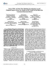
state machines derived from different sequence diagrams is based upon identifying similar states in the FSMs. Ultimately, similarity is a heuristic measure because the sequence diagrams contain incomplete information. However, merging such states is worthwhile – generated states with little or no merging tend to be difficult to understand. Similarity will not be discussed in this paper and so is not defined. We now apply the synthesis algorithm to the composed interaction in Figure 7. Figure 8 shows a state machine produced by the algorithm for the Lot Exit Machine. State machines can also be generated for the other objects in the interaction and the whole system can be simulated by injecting events using commercially available tools. s1
timeout / alertSupervisor ( t ); displayErrorMessage
insertTicket( t ) sensorValidatedTicket / close
s5
aspects with non-aspectual class models, but do not compose interaction properties of aspects with interaction models.
6. CONCLUSIONS This paper presented an approach to modeling interactions using aspect-oriented principles. Aspectual interactions are modeled using Interaction Pattern Specifications and are composed with non-aspectual interactions. This composition is realized through instantiation and composition rules. The approach also includes the generation of state machines from composed scenarios, which can be used to validate the interactions. The technicalities of the approach are described in [8]. This paper validates the ideas using a car parking system example and focuses on error-handling aspects. The advantages of the approach are common to aspect-oriented software development in general: better modularization and traceability in order to achieve system evolveability. This is reflected in the flexible and simple way that the composition rules are expressed. Future work will address how to use the result of the validation step to augment or correct the interaction models.
s2 entry/ checkTicket ( t) / recordTransaction( t ); ejectTicket; open
s3 takeTicket
s4
Figure 8: State machine for Lot Exit Machine
5. RELATED WORK Rashid et al. [4] support separation of crosscutting properties at the requirements level. Composition rules are defined using XML. They use a list of constraint actions and operators, which are used to specify how an aspectual requirement influences or constrains the behavior of a set of non-aspectual requirements. Moreover, a conflict resolution scheme is presented. Georg et al. [3] propose an aspect-oriented design approach that defines an aspect through role models to be woven into UML diagrams. The approach is similar to ours in that aspects are treated as patterns. In particular, interaction aspects may be modeled as interaction role models. However, [3] does not allow concrete modeling elements in the role models. The addition of concrete modeling elements may be useful in practice to reduce the number of instantiations that the user must provide. In addition, [3] only considers instantiation for interaction role models, not composition of role models with non-aspectual interactions. Finally, [3] does not address validation of the interactions. Clarke and Walker [1] use UML templates to define aspects. Interaction pattern specifications provide a much more precise way of defining aspects. [1] also is concerned more with how to specify the aspects rather than weaving aspects into non-aspectual models. Clarke and Walker compose static structural properties of
7. REFERENCES [1]. S. Clarke and R. J. Walker, "Composition Patterns: An Approach to Designing Reusable Aspects". Proceedings of the 23rd International Conference on Software Engineering (ICSE), 2001. [2]. D-K. Kim, R. France, S. Ghosh and E. Song, "Using RoleBased Modeling Language (RBML) as Precise Characterizations of Model Families", In Proceedings of The 8th IEEE International Conference on Engineering of Complex Computer Systems (ICECCS 2002. [3]. G. Georg, I. Ray and R. France. “Using Aspects to Design a Secure System”. 8th IEEE International Conference on Engineering of Complex Computer Systems (ICECCS’02), Greenbelt, Maryland, USA, 2 – 4 December, 2002. [4]. A.Rashid, P. Aspects: A Engineering". Requirements 202.
Sawyer, A. Moreira, and J. Araújo, "Early Model for Aspect-Oriented Requirements IEEE Joint International Conference on Engineering, 2002, IEEE CS Press, pp. 199-
[5]. Unified Modeling Language Specification, version 1.5, January 2003. Available from the Object Management Group, http://www.omg.org [6]. J. Warmer and A. Kleppe, “The Object Constraint Language: Precise Modeling with UML”. Addison-Wesley Object Technology Series. Addison-Wesley, 1999. [7]. J. Whittle and J. Schumann. “Generating Statechart Designs from Scenarios”. Proceedings of the International Conference on Software Engineering (ICSE) 2000, pages 314-323. [8]. J. Whittle and J. Araújo. “Scenario Modeling with Aspects”. IEE Proceedings Software. Under review.