’98
Validating Distributed Software Modeled with UML Jean-Marc Jézéquel, Alain Le Guennec, François Pennaneac'h Irisa/CNRS Campus de Beaulieu F-35042 Rennes Cedex, FRANCE Phone +33-299847192 Fax +33-299847171 Email jezequel/aleguenn/
[email protected]
Abstract
The development of correct OO distributed software is a daunting task as soon as the distributed interactions are not trivial. This is due to the inherent complexity of distributed systems (latency, error recovery, etc.), leading to numerous problems such as deadlocks, race conditions, and many difficulties in trying to reproduce such error conditions and debug them. The OO technology is ill equipped to deal with this dimension of the problem. On the other hand, the willingness of mastering this complexity in the context of telecommunication protocols gave birth to specific formal verification and validation tools. The aim of this paper is to explore how the underlying technology of these tools could be made available to the designer of OO distributed software. We propose a framework allowing the integration of formal verification and validation technology in a seamless OO lifecycle based on UML, the Unified Modeling Language.
1. Introduction It is now widely admitted [8] that only system development based on "real-world" modeling is able to deal with the complexity and the versatility of large software systems. Once the idea of analyzing a system through modeling has been accepted, there is little surprise that the object-oriented (OO) approach is brought in, because its roots lie in Simula67, a language for simulation designed in the late 1960s, and simulation basically relies on modeling. This is the underlying rationale of the numerous object-oriented analysis and design (OOAD) methods that have been documented in the literature [15]. OOAD methods allow the same conceptual framework (based on objects) to be used during the whole software lifecycle. This seamlessness should yield considerable benefits in terms of flexibility and traceability. These properties would translate to better quality software systems (fewer defects and delays) that are much easier to maintain because a requirement shift usually may be traced easily down to the (object-oriented) code. But today many such large software systems have acquired a distributed nature. This distributed nature may be either a constraint from the problem statement, or may be introduced as the consequence of a design decision to handle performance problems and/or fault tolerance. Solutions such as CORBA help in deploying distributed solutions, but any experienced software engineer recognizes that the design, implementation and maintenance of correct distributed software is still a very difficult exercise. Distributed systems have indeed an inherent complexity resulting from fundamental challenges such as latency of asynchronous communications, error recovery, service partitioning and load balancing. Furthermore, being intrinsically concurrent, distributed software faces race conditions, deadlock, starvation problems, etc. This complexity is quite orthogonal to the programming-in-the-large problems addressed by OO technology, including CORBA. There are currently no approaches to deal with this aspect of the problem in an OO context (see [13, 16] for a good overview on current approaches at V&V for OO systems). The nature of the complexity of distributed systems has been widely explored in many academic (and other) circles for several years. In the context of telecommunication protocols, the willingness of mastering this complexity gave birth to the development of standardized formal description techniques (FDT) and to a set of associated formal verification and validation tools. Unfortunately, for several reasons that we explore later in this paper, these tools usually cannot be easily used in an integrated OO lifecycle. The aim of this paper is to explore a way by which the underlying technology of these formal verification and validation tools could be made available to the designer of OO distributed software. We start in Section 2 by recalling what the principles of formal verification and validation tools are, and how they address the inherent
-1-
’98 complexity of distributed systems. We then try to analyze why they are still seldom used. In Section 3, building on this analysis, we outline a tentative OO framework making possible the use of formal verification and validation technology. We illustrate this approach with a simple yet significant case study (a distributed diary system). In Section 4 we describe the various formal verification and validation activities that may be conducted on the case study within our framework. Finally, we conclude on the applicability of our approach for real size cases, and on the perspectives of the integration of formal verification and validation technology in the OO lifecycle.
2. Validating Distributed Software with Formal Description Techniques 2.1. A set of complementary techniques Validation techniques vary widely in their forms and their abilities, but they always need a formal description of the distributed software system. They output data on properties of the system under consideration that can be viewed with some confidence level. Basically, the designer may attack his/her software by three complementary techniques. We list here their advantages and major drawbacks: ?
Formal verification of properties: it gives a definite answer about validity by formally checking that all possible executions of the distributed software respect some properties (e.g. no deadlock). But existing methods, such as model checking, that is the construction of the graph of all the states the distributed system could reach, can only be easily applied to the analysis of very simplified models of the considered problem [5]. Otherwise there is a combinatorial explosion of the number of states that forbids such brute force verification. This forces the distributed software to be described at a high abstraction level, so its formal verification leaves the problem of property preservation during its refinement course wide open.
?
Intensive simulation, using a simulated (and centralized) environment: it can deal with more refined models of the problem and can efficiently detect errors (even tricky or unexpected ones) on a reasonable subset of the possible system behaviors. Formally, it consists in randomly walking the reachability graph of the distributed software. The main difficulty is to formally describe and simulate the execution environment. This is generally quite simplified, because it would not be realistic (nor interesting) to take into account all the parameters of a real system, such as the exact influence of message size on transmission delays, or the exact operation duration (which are not computable without execution).
?
Observation and test of an implementation: here, the execution environment is a real one. But since there is a lack of tools to observe a distributed system as a whole, it will be difficult to actually validate the software. It will also be difficult to generalize the possible behaviors from the observation. Even something as simple as trying to reproduce a test result is not straightforward, because the asynchronous nature of the communications makes the distributed system look non-deterministic.
It appears that these approaches are more complementary than in competition, and that an advised project manager would try to use them all. However this is hard in practice because the formalisms used in these various stages differ widely. Most of these techniques have been developed in the context of the Formal Description Techniques (FDTs) for protocols, where they have been successfully applied to various toy and real problems.
2.2. Difficulties in using FDTs It is very disappointing to see that formal validation based on standard FDTs (such as SDL [2], Estelle [7] and Lotos [6]) never acceded to a widespread use in the industry, despite excellent results on most of the pilot projects where it has been used [10]. While the interest of formal techniques is widely acknowledged (at least in the context of mission critical distributed software), their use is still deferred for various reasons: ?
their learning curve is very steep, because they rely on non-trivial formalisms and unusual syntax and semantics,
?
they require the analysis to be much more accurate in the early stages (which is not necessarily a bad thing, but it is a matter of facts that few projects are prepared to pay the additional cost early),
-2-
’98 ?
And there is a lack of integration of this promising technology in widely used software development methods and lifecycles.
In our experience, this last point is probably the most important one. Because standard FDTs lack basic support for modern software engineering principles, it is extremely clumsy to try to use them as implementation languages for real, large scale distributed applications. Furthermore, being fully formal implies that FDTs are based on a close world assumption, making them awkward to deal with the open nature of many distributed software: specifiers become prisoners of the FDTs underlying semantics choices. For example, all FDTs force a given communication semantics (multi rendezvous for Lotos, FIFO for Estelle) upon the user, who has to painfully reconstruct the set of communication semantics needed for a given distributed system starting from the FDTs one, sometimes with a high performance cost (Estelle FIFO between protocol layers are difficult to circumvent for instance). Using FDTs validation technology thus imposes a model rupture in the usual lifecycle: the formal model for the validation has to be built and maintained separately from the analysis and design model (expressed in e.g., OMT or UML). For example, this implies that formal validation technology may be used during the maintenance phase of a system only after a costly reverse engineering effort. Each time you make a modification in your distributed software, you have to propagate it to the separate model described with your formal description technique, and start all over again your formal validation, which is quite impracticable in the real world. Since the maintenance phase cost for large, long-live systems can represent up to 3 or 4 times its initial development cost, this is not a good point for FDTs. As a consequence, formal validation rarely passes the stage of an annex (and more or less toy) task which gets low priority and low budget.
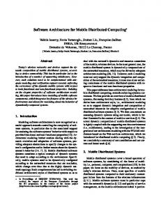
3. Alternative: Integrate Validation in an OO life-cycle 3.1. A new vision for the OO lifecycle OOAD methods along with an OO implementation allow the same conceptual framework (based on objects) to be used during the whole software lifecycle. It should be stressed that the boundaries between analysis, design and implementation are not rigid. Along the ideas proposed in the contract driven lifecycle of Ian Graham (now included into the OPEN methodology [17]), we advocate for extending this seamless OO development process to also encompass validation, not as a post facto task (as promoted in the classical vision of the waterfall or the V-model of the life-cycle), but as an integrated activity within the OO development process. The key point in implementing this idea is to rely on the sound technological basis that has been developed in the context of formal validation based on FDTs, and to make it available to the OO designer through a dedicated framework. Our proposal (see Figure 1) is based on UMLAUT, a tool that can manipulate the UML representation of the system being designed.
Validation Results Problem
Model checking
UML Analysis Model UML Design Model
Implementation
Validation Framework UMLAUT/VALOODS Test
Test Cases
TGV
Test Results Figure 1: Integrating validation in the OO lifecycle -3-
Validation code
TGV Graph API
Test purpose
’98
Formal validation usually takes place on a separate simulation model of the system. This different model must be updated (and revalidated) each time the model is changed, which is both costly and error prone. UMLAUT on the contrary automatically exposes the properties of the system that are relevant to the validation by directly processing its UML representation. An equivalent UML model is automatically produced that explicitly shows the protocol entities involved in asynchronous communications and the new system states that result from those communications. UMLAUT can then proceed to the validation of the UML design: Code fragments are derived from the modified UML model and are "plugged" in a validation framework called VALOODS. This framework comprises a validation engine that will exercise the actual validation. Since this engine is parameterized, one can try the model checking road, or do an intensive simulation, by just choosing the appropriate engine. Moreover, the framework can also serve as a bridge toward more sophisticated validation toolbox such as CADP [3] (by adapting the framework so as to output a transition graph in a format suitable for such a toolbox.) UMLAUT uses CDIF as its exchange format when communicating with other parts of the development environment, which ensures interoperability and independence from CASE tool vendors. Therefore UMLAUT can become a part of the development environment while preserving the investment represented by the other tools already used in the project. Of course, the CDIF output of UMLAUT can be injected back in any CASE tool that supports this format, to see what transformations were actually applied on the original UML model.
3.2. A Validation Framework for OO distributed systems We now outline the principle of the VALOODS framework (VALidation of Object Oriented Distributed Software.) Its purpose is to be a test-bed for OO designs of distributed software, after UMLAUT put them into a form suitable for the application of formal validation technology. A framework consists of a collection of classes together with many patterns of collaboration among instances of these classes. It provides a model of interaction among several objects that belong to classes defined by the framework. The basic abstractions in VALOODS are: ?
Reactive objects, that inherit from the class Reactive and must define the method receive (e : MESSAGE) to handle messages. Messages can be asynchronous messages or signals, or notifications of timer expiration.
?
Pro-active objects, that inherit from the class Activable and must define the methods activable and action. Proactive objects would be run in parallel, using an interleaving semantics for their actions (the method action being atomic).
?
The network interfaces (modeled through the class Port), coming in several flavors (that is, subclasses) in the VALOODS library. This is to model the various addressing schemes and quality of services (e.g. reliable, unreliable, etc.) available to the designer of a distributed software.
The idea of VALOODS is that any class that interacts with a remote site in the distributed system must be a subclass of Reactive or Activable (or both), and use a subclass of Port for its remote communications. Once the complete OO distributed software design has been implemented in this framework, we get an accurate formal representation of the behavior of the distributed software as a whole. Furthermore we get the reversibility for free: if the design needs to be changed, it is easy to validate it again in the VALOODS framework. We no longer have to separately maintain a model of the distributed application for formal validation purposes and the application itself.
-4-
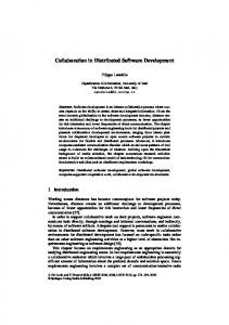
’98 3.3. OO Modeling of a Distributed Diary We could have chosen a multimedia application full of bells and whistles to illustrate our approach; the risk exists that this may have led to unnecessary obfuscation. Or we could have chosen the famous example of the Alternating Bit Protocol, which is commonly used as a cas d'école to evaluate protocol validation tools in the protocol engineering community. Nonetheless, showing the applicability of our approach only on this minimal example may not seem very convincing with respect to its scalability when it comes to more realistic and sophisticated distributed applications. Therefore a trade-off had to be done between the two extreme situations, and the application that we will present in the following sections is a Distributed Diary system, which was originally proposed as a shared case study for the Workshop on Models, Formalisms and Methods for Object-Oriented Distributed Computing (ECOOP'97 Workshop #6) [12]. We are using the Proxy Design Pattern [4] so as to implement a two-phase commit protocol in a manner transparent to the user. The User accesses its local proxy as if it were the diary itself. The proxy then makes sure that all diary copies are kept in sync. The two-phase commit protocol consists in a negotiation between the proxies on the network before transactions are actually committed. Validity constraints can be described at this level with assertions, e.g., on the consistency of the Diary contents.
1: add (EVENT)
4: add (EVENT)
the local Proxy : PROXY
6: ready-to-commit ( ) 10: commit ( )
12: done ( )
a remote Proxy : PROXY
5: add (EVENT)
7: ready-to-commit ( )
3: ready-to-commit ( )
9: done ( )
2: add (EVENT)
13: done ( )
8: commit ( )
11: commit ( )
another remote Proxy : PROXY
the local Diary : DIARY
Figure 2: A transaction in the two-phase commit protocol Figure 2 above describes the messages that the coordinator (the proxy on the site where the transaction is started) exchanges with its remote peers. In this particular case, all sites agree to commit the transaction. In the context of showing the interest of our approach, the interest of this case study is that there are known problems with the two-phase commit protocol (2PC.) Deadlocks can occur under certain circumstances (see [1]). We will see in section 4.3 how VALOODS can be used to find these problems.
-5-
’98 3.4. Making the distributed diary fit into VALOODS Now let us see how UMLAUT transforms the original UML model into a new one suitable for validation, where reactive objects, pro-active objects and network interfaces appear explicitly. The starting point of the transformation is to determine which entities may interact with another one on a remote site. The deployment diagram provides this information. The deployment diagram of the UML model indeed shows the physical location of each component in the delivered distributed system and the relationships among them. Based on this information, the transformations are carried out for both the static and dynamic views of the UML model of the Distributed Diary.
Static model transformations A class whose instances may communicate through the network is considered as the top-level layer of a protocol stack. Since each layer in a protocol stack may have a lower layer and an upper layer and must be able to send information to these layers, this common behavior can be factorized into an abstract class Protocol Entity, which is an heir of the REACTIVE class. Some actions, having a specific behavior depending on the actual layer level, are not described in the class Protocol Entity but in each subclass corresponding to a different layer level. Layers of a protocol stack can be connected using the insert on top operation, and messages are forwarded from one layer to another through the send up and send down operations, respectively. The bottom level layer of a stack is made of an instance of the Port class, which is in charge of the actual network communications. m a n i p u l a te DIARY_INTERFACE
1
1
USER
1 /manipulate
1 +local
+proxy's local
PROXY
1
1 0..*
DIARY
1
+remote
n e g o ci a te with
Figure 3: Class diagram of the system before transformation ?
UMLAUT first adds a generalization (inheritance) association between each class that can have asynchronous communications with remote sites and the PROTOCOL ENTITY class, making them explicit heirs of PROTOCOL ENTITY.
?
Since network communication are handled by instances of the Port class, a protocol stack relationship is established between Port (playing the role of the lower layer) and the classes representing the upper layer (see figure below.)
?
Finally, classes stereotyped as are also made heirs of ACTIVABLE. Objects of the ACTIVABLE class provide a set of stimuli to exercise the dynamic properties of the system. An activable object (e.g. a User consulting the diary) is just an heir of the abstract class ACTIVABLE, which features an entry point called action that may be called from time to time by, e.g., a scheduler, provided the method activable returns true. This way, a validation engine can call the action operation for Users or for network interfaces (i.e. Ports) to arbitrary test the system.
-6-
’98 Figure 4 below represents the same system as the one on Figure 3, after UMLAUT has transformed it according to the rules stated above. protocol stack
1
+upper
PROTOCOL_ENTITY +lower
send/receive
send_down()
MESSAGE
1 send_up() insert_on_top()
DIARY_INTERFACE
1
consult() add() cancel() replace() ready-to-commit() done() commit() a b o r t()
ACTIVABLE isActivable() action()
/manipulate
1
+proxy's local diary DIARY
PROXY
1
1
1
+upper
1
1
USER
0..* PORT peer
/protocol stack
1
EVENT
+lower
0..1
Figure 4: Transformed class diagram
Dynamic model transformations In our framework, the transitions of the UML dynamic model are translated to methods of an OO language according to the following design rules: ?
the triggering event of the transition (if it exists) is transformed in a method parameter,
?
the starting state, plus optional conditions on the event parameters or other conditions on local variables, can be specified in a precondition.
?
the arrival state is specified in the post-condition.
?
the method body must be implemented in such a way that it guarantees the post-condition.
Then we have to provide some implementation details for the control of the automaton. In our framework, the receive method is the "engine" of the automaton associated to protocol entities. It fires transitions (i.e. calls the relevant method) depending on both the received event type and the state in which the object is when the receive method is invoked. The implementation of such a method thus needs a double dispatch operation that has several well-known implementation methods (see e.g. the State design pattern from [4]).
-7-
’98 3.5. Generation of the validation code Once all necessary transformations have been realized, UMLAUT proceeds with the generation of the code that will eventually be plugged into VALOODS for the actual validation to take place. This is done by walking through the connected graph stored in UMLAUT in the form of instances of UML Meta-Model classes. The principle is very similar to the generation of implementation code as usually performed by various CASE tools, except that the code is produced to fit the VALOODS framework. Because the first prototype of VALOODS was written with Eiffel [14], UMLAUT also generates Eiffel code. As a side effect, the validity constraints defined on the model (see section 3.3) and the pre- and post-conditions introduced in the dynamic model (see section 3.4.2) directly map to Eiffel assertions whose violation can be trapped by the Eiffel execution environment.
4. Validation in the VALOODS Framework Within this framework, a validation process may be carried on a seamless way. Since our system can now be compiled to a reactive program offering a set of transitions (guarded by activation conditions) located in the activable objects, we have many opportunities to apply the basic technologies that have been developed in the context of FDT based formal validation.
4.1. Model-checking If we want to try the model-checking road, we can use a driver setting the system in its initial state and then constructing its reachability graph by exploring all the possible paths allowed by activable transitions. The only problem is to be able to externalize the relevant global state (made of the states of the Proxy, Diary and User objects, plus the state of the communication files). We basically solve this problem by leveraging the Memento pattern [4]. The main drawback of this approach is that global state manipulations (comparison, insertion in the table, etc.) are then very costly operations that could compromise large-scale model checking.
4.2. Intensive Simulation For larger systems, an intensive simulation (randomly following paths in the reachability graph) would probably be a more fruitful avenue. Running such a simulation involves the use of a scheduler object implementing a redefinable scheduling policy among the activable transitions (e.g., random selection). It is also possible to observe the system, using an observer, as in Veda [9]. An observer is a program that permits to catch and analyze information about execution. It can see every interactions exchanged in the system, and also every internal states of a module. A protocol sequencing error is detected as a precondition violation on the observer (such an error is detected e.g. when the PORT corrupts data). In the case of VALOODS, the execution environment then allows the user to precisely locate and delimit the responsibility of the error, by providing him with an exception history trace including a readable dump of the call stack. For more abstract or complicated properties to be checked on real systems (e.g., that a service behaves like a FIFO and it is live), the observer object could be derived automatically from higher-level specification languages (e.g., temporal logic specifications).
-8-
’98 4.3. Validation results on the Diary The scenario presented in Figure 2 illustrates the ideal situation of a transaction that is conducted without any problem. However, a major problem with the two-phase commit protocol is that the coordinator may block, indefinitely waiting for the answer of a site that is permanently down. After the coordinator has started a transaction (with a broadcast to all sites), it waits for an answer from each site to know whether they accept the transaction (ready-tocommit). If they do, the coordinator enters the second phase and sends a commit message to the remote sites and then waits for an acknowledgment. The problem arises if a remote site crashes (and stays down) after it has agreed to accept the transaction, but before it could process the commit message sent by the coordinator. If this happens, the coordinator stales. This scenario can easily be deduced from the first one by just removing one of the done messages, i.e. message number 12 or 13. When the scheduler reproduces this particular sequence of messages by triggering the corresponding activable objects, it detects that no more transition can be fired to leave the waiting-state because the guard (all done received) is false. The only fireable transitions left consists in starting a new transaction from a remote site that has committed the previous transaction. Since new transactions are bound to fail in a similar manner, all non-crashed sites will successively come into a blocked state. Eventually, there is no fireable transition left and VALOODS issues a deadlock diagnosis and is able to produce an execution trace. Ideally, when the scheduler has driven the system into such a faulty state, the framework would transpose the trace (which may not be easy to read) into an equivalent UML interaction diagram (a sequence diagram or a collaboration diagram) representing the critical scenario. This interaction diagram would then be integrated in the original UML model of the system, providing the designer with a diagnosis of the problem in the notation that they are familiar with. This feedback allows the designer to correct the UML model so as to solve the problem.
5. Conclusion We have shown the interest and feasibility of integrating formal verification and validation techniques in an established OO lifecycle for the construction of correct OO distributed software systems. On the Distributed Diary system example, we have described how a continuous validation framework can be set up to go smoothly from the OO analysis to the OO implementation of a validated distributed system. But this approach is not limited to simple problems: the intensive simulation techniques have already been used on real OO systems, e.g., the implementation of a parallel SMDS server where it has allowed us to detect non trivial problems at early stages of the life-cycle [11]. One of the current limitations with UMLAUT/VALOODS for model checking is the cost of global state manipulations. A solution that we are currently investigating is to interface the VALOODS framework with open validation tools such as the CADP environment [3], in order to leverage the huge know-how they have accumulated to deal with this kind of problem. UMLAUT can be extended to automatically generate from the transformed model a set of routines sufficient to implement the API needed by tools such as those in CADP. The set typically comprises routines to get to the initial state, fire transitions or compare arbitrary states. Concurrently, we plan to consolidate and extend VALOODS to deal with higher level interactions between distributed objects (e.g. in the context of CORBA.) Once UMLAUT/VALOODS is a truly usable validation framework, we will make it widely available (see http://www.irisa.fr/pampa/UMLAUT/).
-9-
’98
References [1] P. A. Bernstein and N. Goodman. An algorithm for concurrency control and recovery for replicated databases. ACM Transactions on Database Systems, 9(4), December 1984. [2] CCITT. SDL, Recommendation Z.100, 1987. [3] J.-C. Fernandez, H. Garavel, L. Mounier, C. Rodriguez A. Rasse, and J. Sifakis. A toolbox for the verification of programs. In International Conference on Software Engineering, ICSE'14, Melbourne, Australia, pages 246-259, May 1992. [4] Erich Gamma, Richard Helm, Ralph Johnson, and John Vlissides. Design Patterns: Elements of Reusable ObjectOriented Software. Addison Wesley, 1995. [5] S. Graf, J.L. Richier, C. Rodriguez, and J. Voiron. What are the limits of model checking methods for the verification of real life protocols? In Proceedings of the International Workshop on Automatic Verification Methods for Finite State Systems, Grenoble, France, June 1989. Springer-Verlag, LNCS #407, pages 189-196. [6] ISO. LOTOS, A Formal Description Technique Based on the Temporal Ordering of Observational Behaviour. ISO/ DP 8807, March 1985. [7] ISO. Estelle: a Formal Description Technique based on an Extented State Transition Model. ISO 9074 TC97/SC21/WG6.1, 1989. [8] M.A. Jackson. System Development. Prentice-Hall International, Series in Computer Science, 1985. [9] C. Jard, R. Groz, and J.F. Monin. Development of VEDA: a prototyping tool for distributed algorithms. In IEEE Trans. on Software Engin., volume 14,3, pages 339- 352, March 1988. [10] J.-M. Jézéquel. Experience in validating protocol integration using Estelle. In Proc. of the Third International Conference on Formal Description Techniques, Madrid, Spain, November 1990. [11] J.-M. Jézéquel, X. Desmaison, and F. Guerber. Performance issues in implementing a portable SMDS server. In IFIP, editor, 6th International IFIP Conference On High Performance Networking, pages 267-278. Chapman & Hall, London, September 1995. [12] Jean-Marc Jézéquel and François Pennaneac'h. Preliminary ideas for validating distributed oo software. In Workshop on Models, Formalisms and Methods for Object Oriented Distributed Computing (ECOOP'97 Workshop #6), Finland, June 1997. [13] S. Kirani. Specification and Verification of Object-Oriented Programs. Phd thesis, University of Minnesota, 1994. [14] B. Meyer. Eiffel: The Language. Prentice-Hall, 1992. [15] D. E. Monarchi and G. I. Puhr. A research typology for object-oriented analysis and design. Communications of the ACM, 9(35):35-47, September 1992. [16] R. M. Poston. Automated testing from object models. Communications of the ACM, 37(9):48-58, September 1994. [17] I. Graham and B. Henderson-Sellers and H. Younessi. The OPEN Process Specification. Addison-Wesley, 1997.
- 10 -