Modeling Current Density Distribution Inside Proton ... - IEEE Xplore
Recommend Documents
computer science coupled with the rapidly growing aging population are both causes for concern in society. Computer science majors have diminished since ...
High power gyrotrons using oversized cylindrical resonators, tapers and ... spatially distributed in the far-field radiation of the open-ended wave- guide.
Jun 14, 2014 - 7, JULY 2014. Focused Current Density Imaging Using Internal. Electrode in Magnetic Resonance Electrical. Impedance Tomography (MREIT).
AbstractâObjective: Transcranial direct current stimulation. (tDCS) is a neuromodulatory technique for neuropsychiatric dis- eases and neurological disorders.
Xinlei Zhu, Xiaobing Zou, Shen Zhao, Huantong Shi, Ran Zhang, Haiyun Luo, and Xinxin Wang. Abstractâ Wire explosion is the initial stage of the development.
1131. Modal Birefringence and Power Density Distribution in Strained Buried-Core Square Waveguides. Henry P. Schriemer, Member, IEEE, and Michael Cada, ...
Recently, the UWB technology has experienced many significant developments. Freescale Semiconductor was the first company that has successfully produced ...
Jul 20, 2012 - AbstractâIn this letter, a drain current noise model that in- cludes the ... CONTINUED scaling of technology and the demand for extremely low ...
Abstract- This paper continues the efforts on behaviorally modeling multiple-module inter-connected power supply systems
Pulsewidth-modulated (PWM) inverters are used more and more to operate electrical machines and to interface renewable energy systems with the utility grid.
Potential and Drain Current Modeling of. Gate-All-Around Tunnel FETs Considering the. Junctions Depletion Regions and the Channel. Mobile Charge Carriers.
Sub-Threshold Analysis and Drain Current Modeling of Polysilicon Thin-Film Transistor Using. Green's Function Approach. Amit Sehgal, Tina Mangla, Sonia ...
the CM currents to flow on a motor side of the system and reduces the conducted emissions measured on a supply side of the inverter (e.g. by means of LISN).
made about low speed electrical machines for the marine current generators and ... inductances are also not like Pole Salient Permanent Magnet Generator ...
AbstractâThe behavior of leakage current and electric field of insulators primarily depends on the environmental stresses. A mathematical analysis based on ...
School of Electrical Electronic Computer Engineering, University of Newcastle Upon Tyne,. NE1 7RU Newcastle Upon Tyne, U.K.. Department of Engineering ...
Feb 26, 2002 - Dr. Hans Kirchmayr, head of the Institute of ...... ticular the soâcalled de HassâVanâAlphen oscillations were characterized. Under the influence ...
characterize and analyze power distribution networks (PDNs) accurately. This paper ... Index TermsâPower distribution network, transmission matrix method, ...
Interposer Power Distribution Network (PDN). Modeling Using a Segmentation Method for 3-D ICs With TSVs. Kiyeong Kim, Jong Min Yook, Junchul Kim, ...
AbstractâProton therapy, long regarded as a superior method of radiation therapy, is now becoming more cost effective and is being used in a number of ...
To estimate the local current density [13] on the cathode in Haring âBlum [1] cell ..... F.W.Hewes, âCathodic Protection Theory and Practice,â V. Ashworth and ...
â Department of Teacher Training in Electrical Engineering, Faculty of Technical Education,. King Mongkut's University of Technology North Bangkok, Bangkok, ...
Five features extraction methods were tested along with the three optical flow methods. FAST features with horn-schunck estimates crowed density better than.
clustering, big data. I. INTRODUCTION. Clustering algorithms have long been considered useful methods of extracting information from large datasets,.
Modeling Current Density Distribution Inside Proton ... - IEEE Xplore
IEEE TRANSACTIONS ON MAGNETICS, VOL. 48, NO. 2, FEBRUARY 2012. 699. Modeling Current Density Distribution Inside Proton-Exchange Membrane.
IEEE TRANSACTIONS ON MAGNETICS, VOL. 48, NO. 2, FEBRUARY 2012
699
Modeling Current Density Distribution Inside Proton-Exchange Membrane Fuel Cells Federico Moro1 , Ruben Specogna2 , Andrea Stella1 , and Francesco Trevisan2 Dip. di Ingegneria Elettrica, Università di Padova, Via Gradenigo 6/A, Padova I-35131, Italy Dip. di Ingegneria Elettrica, Gestionale e Meccanica, Università di Udine, Via delle Scienze 208, Udine I-33100, Italy A numerical model of the cathode of a proton-exchange membrane fuel cell (PEMFC) based on the discrete geometric approach is presented. The current density distribution inside a PEMFC cathode is simulated. The discrete formulation of a steady-state conduction problem in nonisotropic media is coupled to nonlinear boundary conditions representing the charge transfer at catalyst layers. The cathode performance is assessed under different load conditions by assuming a constant voltage operation mode. Results are in good agreement with those presented in the literature. Index Terms—Discrete geometric approach, fuel cell, nonlinear conduction, proton-exchange membrane fuel cell (PEMFC).
I. INTRODUCTION
D
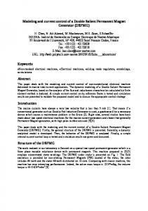
URING the last decade, the idea of a sustainable development based on eco-compatible technologies has drawn increasing attention. Fuel-cell technologies, being based on clean, efficient, and low impact electrochemical processes, have been widely investigated [1], [2]. These devices produce electric power from oxidation of hydrogen or other fuels, which are continuously supplied. Fuel cells are an important technology for a wide variety of applications, including automotive and distributed generation. Proton-exchange membrane fuel cells (PEMFCs) are considered to be the most suitable fuel cells for transportation and portable applications due to their low operating temperature, high energy density, and efficiency. PEMFCs consist of a membrane electrode assembly (MEA) sandwiched between the anode (ACC) and the cathode current collectors (CCCs) in Fig. 1. The MEA can be divided into five layers compounded together: the anodic/cathodic catalyst layers (ACL and CCL) are dispersed on both sides of the polymeric electrode membrane (PEM), which is interleaved between the gas anodic/cathodic diffusion layers (ADL and CDL). Chemical reactions take place at catalyst layers where three different phases coexist. Triple-phase boundaries (TPBs) are the most active sites for electrode reactions since electrode particles, electrolyte phase, and gas pores intersect. These complex phenomena are quite difficult to be modeled, even though some attempts have been made with approximate models like the one presented in [3]. The reactants flow through diffusion layers from flow channels to the catalyst layers. Oxygen is typically taken from the atmospheric air and hydrogen is stored in high-pressure vessels or in metal hydride cartridges. Electric charges follow different paths: electrons are drawn from the TPB by the anode diffusion layer and flow to the external circuit through current collectors, while protons flow through the PEM. Electrons and protons are consumed in the oxygen reduction reaction producing water. In this context, mathematical models are useful for interpreting experimental data and designing optimized fuel-cell configurations. A higher current density for a given cell voltage
Manuscript received June 27, 2011; revised October 11, 2011; accepted October 24, 2011. Date of current version January 25, 2012. Corresponding author: F. Trevisan (e-mail: [email protected]). Color versions of one or more of the figures in this paper are available online at http://ieeexplore.ieee.org. Digital Object Identifier 10.1109/TMAG.2011.2174141
Fig. 1. PEMFC structure: the membrane electrode assembly is sandwiched between the anode and cathode current collectors.
and more uniform current density on the cross section are the current issues under investigation. Several mathematical models have been developed to investigate the effect of various design and operating conditions on the fuel-cell performance and to understand the underlying mechanism, either for solid-polymer-electrolyte or PEMFCs [4]–[6]. Moreover, advanced computational models (multidimensional, multiphase models), which account simultaneously for electrochemical kinetics, current distribution, hydrodynamics, and multicomponent transport may provide a more accurate picture of transport and kinetic phenomena in PEMFCs with different flow distribution strategies [7]. The aim of this paper is to develop a numerical simulation model of the electronic conduction inside the cathodic CDL attached to a segmented graphite current collector. In a typical PEMFC, one of the basic features to be improved is the average current density for a fixed operating cell voltage. On the other hand, uniformity of current density distribution across the entire active area is essential for performance optimization. The effect of several features, such as electrode configuration, air-flow rate, fuel and oxidant gas stream humidity, and cell temperature on the spatial and temporal current density distribution have been investigated by representing the PEMFC cathode as a segmented electrode/current collector assembly as described in [8] and [9]. The electric scalar potential distribution is simulated by solving a nonlinear, anisotropic conduction problem, where field equations are expressed directly in algebraic form
IEEE TRANSACTIONS ON MAGNETICS, VOL. 48, NO. 2, FEBRUARY 2012
by means of the discrete geometric approach (DGA) [11], [10]. The current density distribution can be easily computed from potential distribution in order to estimate its degree of uniformity through the entire active area of the electrodes [9]. As a result, it is possible to increase the current density for a given working cell potential. II. DISCRETE GEOMETRIC MODEL We propose a 2-D discrete geometric model of the cathode region, where the electronic conduction occurs. Due to the periodic symmetry of the model, only a part of the electrode strucas the ture is considered. We denote domain of interest, consisting of a CDL region and one , half of two adjacent graphite current collectors plates separated by an insulating region (Fig. 2). The upper part of the boundary of the region is in tight contact with the cathode catalyst layer, where electric charges are consumed due to the oxygen reduction reaction. The cathode catalyst layer is assumed to be a zero-thickness region since its dimension is typically negligible compared to that of the other layers of the MEA.
A. Domain Discretization is disAccording to the DGA, the computational domain cretized into a pair of interlocked cell complexes, one dual of the other (Fig. 3). In our 2-D field problem, the current density plane; J and electric field E are assumed to be parallel to the the primal cell complex consists of nodes , edges , faces1 , and volumes (prisms with triangular base) ; we denote with , , , and the cardinalities of the corresponding sets of geometric elements, respectively. The dual cell complex, consisting of dual faces2 , dual edges , and dual nodes , is obtained according to the barycentric subdivision from the primal complex [11]. Since the problem is 2-D and the current density and elecplane, we consider the projection on a tric field lie in the plane of such a pair of interlocked grids; therefore, the primal volumes correspond to triangles with , and the primal faces correspond to edges. In the following text, we will denote as the incidence matrix of dimension between primal edges and primal nodes, with as the incidence matrix of dimension between primal faces and primal representing the incidence matrix edges, and with of dimension between dual volumes and dual faces.
Fig. 2. Two-dimensional model on the (x; y ) plane of a segmented electrode at the cathode. (The picture is not scaled proportionally.) The cathode catalyst layer (CCL)—where reactions take place—is evidenced on the top.
Fig. 3. Geometric entities of primal and dual cell complexes tailored inside the primal volume v in a one-to-one correspondence with triangle s; in particular, primal nodes n and primal edges e are evidenced, since they define a 2-D planar mesh. The thickness of the triangular prism v is denoted by d.
where is the array of the voltages on primal edge , with ; denotes the th entry of the array . We define as the array of the electric scalar potentials associated with each primal node , with (Fig. 2). By noting that , (1) can be implicitly enforced at the discrete level by means of electric scalar potentials as (2) The current continuity law can be written as the following algebraic relation:
B. Nonlinear Discrete Conduction Problem The behavior of the cathode catalyst layer is simulated by introducing appropriate nonlinear Neumann boundary conditions, which account for the electric charge transfer rate. According to the DGA, the physical laws governing the nonlinear conduction problem inside the cathode region can be expressed exactly by means of algebraic relations between degrees of freedom using only the topological information of the mesh embedded in the incidence matrices. Hence, Faraday’s law for stationary fields can be expressed with the DGA directly in algebraic form [12] as (1) 1Each 2Each
surface is of thickness d and its trace is a line in the xy plane. dual surface is of thickness d and its trace is a line in the xy plane.
(3) are arrays of current of dimension ; denotes where , the array of source currents, which depends nonlinearly on the electric scalar potential. The Ohm’s law between fields can be expressed in discrete form with a constitutive matrix that links the array of voltages to the array of currents as (4) The square matrix of dimension encodes the information of the material properties and of the geometry of the problem. The constitutive matrix can be easily constructed in a geometric fashion (i.e., by applying for triangles the same ideas developed
MORO et al.: MODELING CURRENT DENSITY DISTRIBUTION
701
in [12] and [13] for tetrahedra) in such a way that (4) holds exactly for an element-wise uniform electric field E, electric curin each volume . rent density J, and conductivity tensor
TABLE I ELECTRIC PARAMETER VALUES USED IN THE MODEL
C. Modeling the Catalyst Layer in a neighborhood of each node The current density in the catalyst layer can be modeled according to the Butler–Volmer equation accounting for, for example, the PEM hydration, the reactant and product concentration, and temperature [8], [9] (5) where is the equilibrium potential characteristic of the electrochemical reaction, is the cathode Tafel constant, and is the apparent exchange current density. By multiplying the current density by the area of the dual face , the corresponding source current is obtained, where is model thickness and is the width (Fig. 2). Thus, is a prescribed function of the electric potential in the node . If the node belongs to the catalyst layer, is the current crossing the dual face correthen sponding to the node ; the entries of are null for any other node not belonging to the catalyst layer. III. NONLINEAR COUPLED PROBLEM By inserting (2) and (4) in (3), the following algebraic system of equations is obtained: (6) is obtained by assembling The global stiffness matrix the contributions from the local stiffness matrices of each triangle in a one-to-one correspondence with a primal volume , with . The entry of a local symmetric stiffness matrix can be expressed efficiently [12] in a pure as geometric way for the triangle (7) is the area of , and is the area vector3 associated where with the lateral face of . In the CDL region , the local conductivity tensor in is diagonal, but it represents an anisotropic conductivity along orthogonal directions, while the conductivity of the bulk graphite collector regions is isotropic. Dirichlet or Neumann linear BCs must be considered in adlines to ensure the uniqueness of the dition along with solution (Fig. 2). For constant voltage operation, the potential is imposed to a fixed value; for constant current operation, a is imposed and, congiven uniform current density along sequently, the potential of the equipotential interfaces is computed; in both cases, the potential is unknown along the catalyst layer. Finally, symmetry BCs on the lateral sides of region are applied. IV. NUMERICAL RESULTS The potential distribution in the cathodic region of a segmented electrode cathode of a PEM fuel cell is analyzed by considering a portion of the periodic current collector structure de3It is normal to the lateral face f of the prism and it points outward v ; moreover, due to the plane symmetry, jf j = je j holds.
picted in Fig. 2. The geometric data and the electric parameter values reported in Table I refer to the fuel cell described in [9]. We solve the nonlinear system (6) by means of a Newton–Raphson method. The Jacobian can be evaluated from the residual of the nonlinear system (8) as (9) denotes the element of the matrix in the th row where and th column, and is the Kronecker delta function. The flowchart of the iterative solution scheme adopted for the solution of the nonlinear system (6) is reported in Fig. 4. In order to improve the convergence rate, we also experimented with a across locally linearized expression of the electron current a dual face instead of (5) (10) V cm A. where As a boundary condition, we implemented the so-called constant voltage operation of the fuel cell, where the potential of the primal nodes on is imposed on 0.695 V, which is the normal voltage operation of the cell described in [9]. The domain is discretized with a very refined mesh (85 347 nodes, 168 094 triangles). The overall simulation time is about 10 s, including the preprocessing, the computation, two Newton–Raphson steps and postprocessing. Figs. 5 and 6 show the resulting overall potential and current density distribution at the cathode for a constant voltage operation mode of the fuel cell. These results are in the same order of magnitude with those reported in the literature obtained by means of a finite difference method [9]. Since contact resistances, which deeply affect numerical and experimental results, are not implemented in our model, a more direct comparison cannot be carried out. Results concerning the constant current operation are not provided in this paper for the sake of brevity. In that case, instead of fixing the potential of the primal nodes on and by means of Dirichlet BCs, the total current crossing dual faces—in one-to-one correspondence with primal nodes on and —is known and can be imposed by means of Neumann BCs. V. CONCLUSION The developed coupled model is suitable for analyzing electronic conduction in the cathode current collectors of PEMFCs. The DGA makes use of integral variables, which makes it possible to implement in a straightforward manner nonlinear Neumann BCs. In fact, primal nodes—where potential is associ-
702
IEEE TRANSACTIONS ON MAGNETICS, VOL. 48, NO. 2, FEBRUARY 2012
Fig. 6. Planar distribution on the (x; y ) plane of the electronic current density distribution in the cathode of the fuel cell computed at constant voltage operation.
ACKNOWLEDGMENT This work was supported by the Italian Ministry of University and Research (MIUR). Fig. 4. Flowchart of the iterative Newton–Raphson scheme used for solving the nonlinear system.
Fig. 5. Potential distribution calculated with the DGA for a constant voltage operation of the fuel cell. The top part of the plot shows the potential distribution at the catalyst layer.
ated—and dual faces—where currents are associated—are in one-to-one correspondence as can be observed in Fig. 2. This peculiarity makes the coupling natural between the classical current conduction model and the Butler–Volmer equation. The results obtained with the DGA are in the same order of magnitude with those presented in [9], obtained by means of a finite difference method, and show overall good agreement in terms of qualitative behavior. A further development will be the inclusion of contact resistances in the discrete model.
REFERENCES [1] J. Larminie and A. Dicks, Fuel Cell Systems Explained. Hoboken, NJ: Wiley, 2003. [2] S. Gottesfeld, “Advances in electrochemical science and engineering,” in Polymer Electrolyte Fuel Cells. Hoboken, NJ: Wiley-VCH, 1997, vol. 5. [3] R. O’Hayre, D. M. Barnett, and F. B. Prinz, “The triple phase boundary: A mathematical model and experimental investigations for fuel cells,” J. Electrochem. Soc., vol. 152, no. 2, pp. A439–A444, 2005. [4] T. E. Springer, M. S. Wilson, and S. Gottesfeld, “Modeling and experimental diagnostics in polymer electrolyte fuel-cells,” J. Electrochem. Soc., vol. 140, no. 12, pp. 3513–3526, 1993. [5] T. F. Fuller and J. Newman, “Water and thermal management in solid PEMFC,” J. Electrochem. Soc., vol. 140, no. 5, pp. 1218–1225, 1993. [6] C. Y. Wang, “Fundamental models for fuel cell engineering,” Chem. Rev., vol. 104, no. 10, pp. 4727–4765, 2004. [7] T. Berning and N. Djilali, “Mathematical modeling of proton exchange membrane fuel cells,” J. Electrochem. Soc., vol. 150, no. 12, pp. A1589–A1598, 2003. [8] K. Scott and P. Argyropoulos, “A current distribution model of a porous fuel cell electrode,” J. Electroanal. Chem., vol. 567, no. 1, pp. 103–109, 2004. [9] D. Natarajan and T. V. Nguyen, “Effect of electrode configuration and electronic conductivity on current density distribution measurements in PEM fuel cells,” J. Power Sources, vol. 135, no. 1–2, pp. 95–109, 2004. [10] A. Bossavit, “How weak is the weak solution in finite elements methods?,” IEEE Trans. Magn., vol. 34, no. 5, pp. 2429–2432, Sep. 1998. [11] E. Tonti, “Finite formulation of the electromagnetic field,” IEEE Trans. Magn., vol. 38, no. 2, pp. 333–336, Mar. 2002. [12] R. Specogna and F. Trevisan, “Discrete constitutive equations in A geometric eddy-currents formulation,” IEEE Trans. Magn., vol. 41, no. 4, pp. 1259–1263, Apr. 2005. [13] F. Trevisan and L. Kettunen, “Geometric interpretation of finite dimensional eddy current formulations,” Int. J. Numer. Meth. Eng., vol. 67, no. 13, pp. 1888–1908, 2006.