The hybrid-Trefftz formulation of the finite element method is applied to the ... 6. 1.3.3 Tenets of biphasic theory. 7. 1.3.4 Soft tissue modelling. 9. 1.4 Trefftz Finite Element Modelling. 12 .... Appendix A: Non-Periodic Spectral Decomposition. 221 .... tissue material, is used in this section to explain briefly how this biomaterial.
UNIVERSIDADE TÉCNICA DE LISBOA INSTITUTO SUPERIOR TÉCNICO
MODELLING OF HYDRATED SOFT TISSUES USING HYBRID-TREFFTZ FINITE ELEMENTS Milan Toma (Mestre) Dissertação para obtenção do Grau de Doutor em Ciências da Engenharia Orientador: Doutor João António Teixeira de Freitas Júri: Presidente: Reitor da Universidade Técnica de Lisboa Vogais: Doutor Roberto Contro Doutor João António Teixeira de Freitas Doutor João Arménio Correia Martins Doutor António Jaoquim Mendes Ferreira Doutor Helder Carriço Rodriques Doutor António Alexandre Trigo Teixeira Novembro de 2007
Resumo A formulação híbrida-Trefftz do método dos elementos finitos é aplicada à análise transiente, geométrica e fisicamente linear, de meios incompressíveis bifásicos saturados. São desenvolvidos dois modelos, o modelo de tensão e o modelo de deslocamento, os quais são aplicados e testados na análise de problemas bidimensionais e axisimétricos. Realizam-se, para cada um dos casos, dois tipos de análise, no domínio da frequência e no domínio no tempo. O modelo de tensão (deslocamento) decorre da aproximação directa do campo de tensões e de pressão (de deslocamento) em cada fase da mistura no domínio do elemento e dos deslocamentos (das forças e da pressão) nas fases sólida e líquida da fronteira do elemento. As bases de aproximação no domínio usadas na implementação dos modelos são extraídas da solução formal do sistema de equações diferenciais que governa o comportamento da mistura. Os modelos são deduzidos directamente das condições fundamentais de equilíbrio, compatibilidade, elasticidade e incompressibilidade. A estrutura dos sistemas resolutivos obtidos para cada modelo é simétrica, a menos dos termos dependentes da velocidade, esparsa, naturalmente p-adaptativa e apropriada ao processamento paralelo. Recuperam-se as condições variacionais que estão associadas com esses sistemas e estabelecem-se condições suficientes para a existência e a unicidade das soluções. Apresenta-se um conjunto amplo de ensaios de validação retirados da literatura da especialidade. Os ensaios realizados no domínio da frequência são utilizados para demonstrar as características de convergência dos elementos. Os ensaios realizados no domínio no tempo são utilizados para avaliar a qualidade da representação dos campos de tensão, pressão, deslocamento e velocidade em cada instante da análise.
i
ii
Palavras-chave
Elementos finitos de Trefftz Meios porosos saturados incompressíveis Análise espectral Análise no domínio do tempo
iii
iv
Abstract The hybrid-Trefftz formulation of the finite element method is applied to the transient, physically and geometrically linear analysis of incompressible saturated porous media. Two finite element models are developed, namely the stress model and the displacement model. The stress (displacement) model develops from the direct approximation of the stress and pressure fields (displacements in each phase of the mixture) in the domain of the element and of the solid and fluid displacements (forces and pressure) on its boundary. The domain approximation bases are extracted from the formal solution of the system of differential equations that govern the behaviour of incompressible saturated porous media. The finite element equations are derived directly from the local conditions on equilibrium, compatibility, elasticity and incompressibility. The structure of the resulting algebraic solving systems is symmetric, except for the velocity induced terms, sparse, naturally p-adaptive and well-suited to parallel processing. The associated variational statements are recovered and sufficient conditions for the existence and uniqueness of the finite element solutions are stated. A comprehensive set of validation tests is presented. The benchmark tests used in the literature are solved in the frequency domain to assess the convergence characteristics of the alternative stress and displacement elements. They are implemented also in the time domain to assess the quality of the estimates they produce for the stress, pressure, displacement and velocity fields at every instant of the analysis.
v
vi
Keywords
Trefftz elements Incompressible saturated porous media Spectral analysis Time domain analysis
vii
viii
Acknowledgments I would like to thank Professor João António Teixeira de Freitas, my supervisor, for being honest and open with me, his guidance through the early years of chaos, confusion and desperation, many suggestions, friendly encouragement and constant support during this research. José Paulo Moitinho de Almeida shared with me his knowledge of programming and Carlos Manuel Tiago Tavares Fernandes provided me many useful references. The FCT Scholarship, which was awarded to me for the period 2003–2007, was crucial to the successful completion of this project. I also want to thank Ionuţ Dragoş Moldovan for being willing to help whenever I needed and the long conversations about our lives in Portugal. Finally, I wish to thank the following: Hugo, Cristina, Peter, Diana, Ivana, Adriana, César, Bruno, Dávid, Roman ... for all the good and bad times we had together. Although, my life in Portugal could be defined as years of solitude, it was definitely worth it.
ix
x
Sumário
i
Palavras-chave
iii
Abstract
v
Keywords
vii
Acknowledgments
ix
1 INTRODUCTION
1
1.1 Motivation and Scope
1
1.2 Object and Objectives
2
1.3 Hydrated Soft Tissues
4
1.3.1 Articular cartilage 1.3.2 Mechanical behaviour 1.3.3 Tenets of biphasic theory 1.3.4 Soft tissue modelling
4 6 7 9
1.4 Trefftz Finite Element Modelling
12
1.4.1 Origin of the concept 1.4.2 Origin of the concept in computational mechanics 1.4.3 Computational fundaments and perception of the method 1.4.4 Application of the concept in computational mechanics
12 13 14 15
1.5 Layout of the Thesis
17
2 BASIC EQUATIONS
19
2.1 Introduction
19
2.2 Notation and Terminology
20
2.3 Governing Parabolic Problem
22
2.3.1 Domain conditions 2.3.2 Boundary conditions 2.3.3 Two-dimensional and axisymmetric problems 2.4 Time Integration
23 24 24 26
2.4.1 Trapezoidal rule analysis 2.4.2 Periodic spectral analysis 2.4.3 Non-periodic spectral analysis
27 28 29
2.5 Equivalent Elliptic Problem
34
2.5.1 Approximations in time
35 xi
2.5.2 Domain conditions 2.5.3 Boundary conditions 2.5.4 Periodic spectral analysis 2.5.5 Trapezoidal rule analysis
35 36 38 38
2.6 Governing Differential Equation
39
2.7 Energy Forms
40
2.8 Closure
41
3 FINITE ELEMENT MODELLING
43
3.1 Introduction
43
3.2 Basic Equations
45
3.3 Finite Element Approximations
47
3.3.1 Approximations in the domain 3.3.2 Trefftz constraint 3.3.3 Approximations on the boundary
47 50 51
3.4 Dual Finite Element Transformations
51
3.5 Overview of the Alternative Formulations and Models
53
3.5.1 Hybrid displacement model 3.5.2 Hybrid stress model 3.5.3 Trefftz variant of hybrid stress and displacement models 3.6 Hybrid Displacement Element
53 55 57 58
3.6.1 Procedure 3.6.2 Elasticity condition 3.6.3 Equilibrium condition 3.6.4 Compatibility condition 3.6.5 Indeterminacy numbers 3.6.6 Solving system 3.6.7 Quality of the finite element solutions 3.7 Hybrid Stress Element
58 59 59 61 61 62 63 64
3.7.1 Procedure 3.7.2 Elasticity condition 3.7.3 Compatibility condition 3.7.4 Equilibrium condition 3.7.5 Indeterminacy numbers 3.7.6 Solving system 3.7.7 Quality of the finite element solutions
xii
64 64 65 66 66 67 68
3.8 Hybrid-Trefftz Formulation
68
3.8.1 Hybrid-Trefftz displacement model 3.8.2 Hybrid-Trefftz stress model 3.8.3 Quality of the hybrid-Trefftz finite element solutions 3.9 Energy Statements and Uniqueness Conditions 3.9.1 Duality and virtual work 3.9.2 Associated quadratic programs 3.9.3 Non-Hermitian problems 3.9.4 Hermitian problems
69 69 70 71 72 72 73 76
3.10 Closure
78
4 PLANE STRAIN AND PLANE STRESS PROBLEMS
81
4.1 Introduction
81
4.2 Basic Equations
83
4.3 Discretization
84
4.3.1 Nodes 4.3.2 Boundary elements 4.3.3 Domain elements 4.3.4 Neumann and Dirichlet boundaries 4.4 Domain Approximation Basis
85 85 86 88 88
4.4.1 Trefftz potentials 4.4.2 Trefftz approximation functions 4.4.3 Dimensions of domain bases
89 90 97
4.5 Boundary Approximation Basis
98
4.6 Finite Element Arrays
99
4.7 Finite Element Solving Systems
100
4.7.1 Displacement model 4.7.2 Stress model
101 103
4.8 Solution and Post-Processing
106
4.9 Testing Problems
109
4.10 Frequency Domain Tests
110
4.10.1 Boundary conditions 4.10.2 Forcing frequencies 4.10.3 Discretization
110 111 112
xiii
4.10.4 Incompressibility tests 4.10.5 Mesh distortion tests 4.10.6 Convergence tests 4.10.7 Stress, pressure and displacement estimates 4.11 Time Domain Tests
113 115 116 120 124
4.11.1 Confined compression test 4.11.2 Unconfined compression test 4.11.3 Indentation test
125 128 134
4.12 Closure
138
5 AXISYMMETRIC PROBLEMS
141
5.1 Introduction
141
5.2 Basic Equations
142
5.3 Discretization
143
5.4 Boundary Approximation Basis
145
5.5 Domain Approximation Basis
145
5.5.1 Trefftz potentials in cylindrical coordinates 5.5.2 Trefftz potentials in spherical coordinates 5.5.3 Trefftz bases 5.5.4 Cylindrical Trefftz solutions 5.5.5 Spherical Trefftz solutions 5.5.6 Dimensions of domain bases
145 146 147 149 150 153
5.6 Finite Element Arrays
154
5.7 Solution and Post-Processing
155
5.8 Testing Problems
158
5.9 Frequency Domain Tests
159
5.9.1 Boundary conditions 5.9.2 Forcing frequencies 5.9.3 Discretization 5.9.4 Incompressibility tests 5.9.5 Mesh distortion tests 5.9.6 Convergence tests 5.9.7 Stress, pressure and displacement estimates
xiv
159 160 160 161 162 165 168
5.10 Time Domain Tests
173
5.10.1 Confined compression test 5.10.2 Unconfined compression test 5.10.3 Indentation test
176 177 185
5.11 Closure
186
6 RESULTS AND FUTURE RESEARCH
187
6.1 Planned Research
187
6.2 Results of the Research
188
6.3 Future Research
194
BIBLIOGRAPHY
197
Appendix A: Non-Periodic Spectral Decomposition
221
Appendix B: Condition Number
223
Appendix C: System Scaling
225
Appendix D: Tikhonov Regularization of Ill-Conditioned Problems
227
xv
xvi
CHAPTER 1 INTRODUCTION
1.1 Motivation and Scope The study reported here is part of an ongoing research programme on the application of the Trefftz concept to the solution of engineering applications using the finite element method, Ref. [1]. Two- and three-dimensional elastostatic applications were used initially to gain experience and establish the basic skills required by this approach, namely in what concerns the modelling of singular stress fields. The following stage of the study addressed the extension to local and gradient-dependent plasticity modelling and to the application of the concept to dynamic analysis problems, in both frequency and time domains. When the study reported here was launched, the main motivation was to assess the performance of the hybrid-Trefftz variant in the modelling dynamic response of biphasic media typically found in Geomechanics, namely saturated soils. At the same time, specialists in Biomechanics encouraged the use of the same technique to overcome a well-established difficulty found in the modelling of the behaviour of conceptually similar biomaterials, namely the incompressibility of hydrated soft tissues. These two complementary studies would serve also the purpose of establishing the basic knowledge and experience necessary to support the nonlinear extension of the hybrid-Trefftz variant of the finite element method, namely to the physically (elastoplastic) nonlinear analysis of saturated soils and to the geometrically (large strain) nonlinear analysis of hydrated soft tissues.
1
However, and as the research on finite element modelling of soft tissues developed, it became clear that the record on finite element linear modelling of the transient response of hydrated soft tissues left open a number of fundamental issues. This fact justified the option to centre this research on linear modelling in order to establish a comprehensive study with the object and objectives identified below.
1.2 Object and Objectives This thesis focuses on the application of the displacement and stress models of hybrid-Trefftz finite formulation to the geometrically and physically linear analysis of the transient response of incompressible biphasic media. The Trefftz concept consists simply in using an approximation basis extracted from the solution set of the governing system of differential equations. When this concept is implemented in the framework of the finite element method released from both node and local conformity concepts, the resulting finite element solving systems are sparse, free of spurious modes, well-suited to adaptive refinement and parallel processing. In the present context, the Trefftz approximation basis satisfies locally all domain conditions that model the response of hydrated soft tissues, namely the equilibrium conditions in both the solid and fluid phases, and not only the mixture, as proposed elsewhere, as well as the constitutive relations and the compatibility conditions, including the mixture incompressibility condition. Besides embodying the physics of the problem, this basis leads to a solving system where all coefficients are defined by boundary integral expressions. Hence, it leads to a formulation that combines the main features of the finite element and boundary element methods, namely domain decomposition and boundary integral expressions, while dispensing the use of (strongly singular) fundamental solutions.
2
Modelling of the response of hydrated soft tissues is usually based on the biphasic theory developed and experimentally validated by V.C. Mow and his coworkers [2]. Typically these models are developed from the discretization in the time domain of the governing system of parabolic equations using trapezoidal time integration rules. The resulting elliptic problem is then solved using the different techniques for boundary value problems reported in literature, namely the penalty, mixed-penalty, mixed and hybrid finite formulations that have been developed for the analysis of hydrated soft tissues. However, and besides modelling of incompressibility of the mixture, which remains a sensitive issue, basic aspects of linear finite element modelling of the behaviour of this particular biomaterial remain unaddressed and justify the objectives set for this study: • To develop naturally hierarchical approximation bases that model locally the domain conditions that govern the linear response of incompressible biphasic media; • To formulate the alternative stress and displacement models of the hybridTrefftz variant of the finite element method, for both the two-dimensional and axisymmetric problems; • To derive the associated energy statements and the conditions for the existence and uniqueness of finite element solutions; • To derive spectral analysis models to assess the performance of the alternative stress and displacement Trefftz elements in terms of convergence and of their sensitivity to gross mesh distortion, wavelength excitation and full incompressibility; • To derive time domain analysis models to asses the performance of the Trefftz elements using a high-order time integration method designed to preserve parabolicity and exploit the use of a naturally hierarchical wavelet time approximation basis;
3
• To encode the finite element formulation in a format suitable to adaptive refinement and parallel processing.
1.3 Hydrated Soft Tissues The term soft tissue refers to tissues that connect, support, or surround other structures and organs of the body. Soft tissue includes muscles, tendons (bands of fiber that connect muscles to bones), fibrous tissues, fat, blood vessels, nerves, and synovial tissues (tissues around joints). To be able to follow the results obtained with finite element simulations, it is important to understand the way a soft tissue works and, to a lesser extent, which are the functions it is responsible for. The knee articular cartilage, a typical soft tissue material, is used in this section to explain briefly how this biomaterial works and to introduce the tenets of biphasic theory, see Ref. [3]. 1.3.1 Articular cartilage There are basically two major phases of the articular cartilage illustrated in Figure 1.1. They are the fluid phase, containing water (68–85%) and electrolytes, and the solid phase, containing collagen type II (10–20%), proteoglycans (5–10%), glycoproteins and chondrocytes. Chondrocytes are the cells that produce the cartilage matrix. These major components (water, collagen, proteoglycans) act together to determine the mechanical behaviour of cartilage. Changes in the relative amounts of these components due to disease will change the time dependent mechanical properties of cartilage. About 30% of the total water exists within the interfibrillar space of collagen. The collagen fibril diameter and the amount of water within the collagen are determined by the swelling pressure due to the fixed charge density of the proteoglycans. In other words, the proteoglycans have strong negative electric charges and they are constrained within the collagen matrix. Because the proteoglycans are bound closely, the closeness of the negative charges creates a
4
repulsion force that must be neutralized by positive ions in the surrounding fluid. The higher concentration of ions in the tissue as compared to outside the tissue leads to swelling pressures. The exclusion of water raises the density of fixed charge, which in turn raises the swelling pressure and charge-charge repulsion.
Joint Cavity
Load
Load
Motion
Articular Cartilage Meniscus
Motion Articular Cartilage
Bone
Load
Load
Subchondral Cortex
(a)
(b)
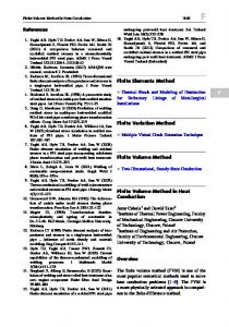
Figure 1.1: Illustration of the knee articular cartilage, Ref. [3]: (a) The knee (0.5−15 cm); (b) The articular cartilage (10−4−10−2 m). The amount of water present in cartilage depends on the concentration of proteoglycans, the organization of the collagen network, and the stiffness and strength of the collagen network. The collagen network resists the swelling of the articular cartilage. If the collagen network is degraded, as in the case of osteoarthritis, the amount of water in the cartilage increases, because more negative ions are exposed to draw in fluid. The increase in fluid can significantly alter the mechanical behaviour of the cartilage. In addition, with a pressure gradient or compression, fluid is squeezed out of the cartilage. When the fluid is being squeezed out, there are drag forces between the fluid and the solid matrix that increase with increasing compression and make it more difficult to exude water. This behaviour increases the stiffness of the cartilage as the rate of loading is increased. Collagen is the component of cartilage that contributes most to tensile behaviour of the tissue.
5
The third major component of cartilage is proteoglycans. Proteoglycans are large biomolecules that consist of a protein core with glycosaminoglycan side chains. These molecules normally occupy a large space when not compacted by a collagen network. The compaction of the proteoglycans affects swelling pressure as well as fluid motion under compression. 1.3.2 Mechanical behaviour There are three major factors that contribute to articular cartilage mechanical behaviour. Firstly, there is the swelling pressure due to the ionic effects in the tissue. Secondly, there is the elastic behaviour of the solid matrix itself. Thirdly, there is the fluid-solid interaction in the cartilage under compressive load, as shown in Figure 1.2. Young’s Modulus = σ / ε Tensile Stress σ
σ
Failure
ε Linear Region
Toe Region
Strain ε
Figure 1.2: Stress-strain curve for soft tissues, Ref. [3]. The mechanical behaviour of the solid matrix is determined by the amount and crimp of collagen in the matrix. Therefore this matrix follows the classic nonlinear stress-strain curve for soft tissues, shown in Figure 1.2, where the regions (a toe region, a linear region, and a failure region) correspond the unfolding of the crimp. The interaction between the fluid and solid phases of the cartilage plays a significant role in the mechanical behaviour of cartilage. The flow of water out of the tissue and the drag this creates on the solid phase are major determinants of the 6
compressive behaviour of the tissues. Thus, in this sense, the mechanical behaviour of the cartilage is very dependent on how easy it is for the fluid to move in and out of the tissue, a property known as permeability. Flow of fluid through solid, permeable matrices is governed by Darcy’s law (1),
Q=
κ A∆ P h
(1)
which relates the rate of volume discharge, Q (m3s−1), through a porous solid with the pressure gradient applied to the solid, ∆P (Nm−2) and the hydraulic permeability coefficient, κ (m4N−1s−1). In the equation above, A is the area (m2) and h is the height of the specimen (m). The permeation speed V (ms−1) measures the volume of discharge per unit area of the fluid. The diffusive drag coefficient measures how much drag the fluid creates on the solid and is defined as follows, where φ f is the volume fraction of the fluid:
ς=
(φ f ) 2
κ
(2)
1.3.3 Tenets of biphasic theory Permeability and load sharing between the solid and fluid components form the basis for the biphasic theory of cartilage behaviour. The tenets of biphasic theory are the following, Ref. [3]: • The solid matrix may be linearly elastic or hyper-elastic with isotropic or anisotropic behaviour; • The solid matrix and the interstitial fluid form an incompressible mixture, which means that the cartilage as whole can only be compressed if fluid is exuded from the system; • The dissipation of energy results from the fluid flow relative to the solid matrix; • The frictional drag of the solid versus the fluid is proportional to the relative velocity, as defined by the diffusive drag coefficient.
7
This theory captures the basic behaviour of cartilage under compression. An example of the response of the cartilage under confined compression is shown in Figure 1.3. The containing chamber is assumed to be rigid, impermeable and lubricated. The loading platen is permeable and lubricated. In this case, the cartilage is subjected to a fixed displacement at instant t0. It is possible to see a large rise of stress in the time-stress graph at instant B. Because the fluid cannot immediately leave, it carries a good portion of the load. As the fluid leaves the cartilage, the load is shifted to the solid matrix and the stress is reduced. Unloaded
O
Fluid efflux and solid matrix compaction Fluid redistribution
A
B
C
Equilibrium
D
E
displacement B C D
E
A O time
t0
Incompressible cartilage sample
stress B
C
A
D
E
O time
Figure 1.3: Cartilage under compression. Equilibrium modulus and permeability are two key material properties in biphasic theory. Equilibrium modulus is the stiffness of the cartilage as all the fluid flows out. In the progression from point O to point A, permeability increases and the equilibrium modulus decreases. As the permeability increases, less
8
loading is shared by the fluid phase, increasing thus the stress level on the solid phase [3]. 1.3.4 Soft tissue modelling Early finite element formulations corresponding to multiphase systems are found in the literature on soils [4-13]. Finite element formulations corresponding to the linear poroelastic theory of Biot [4,5] designed to model the response of saturated soils [9,10] have also been applied to study the deformational behaviour of the intervertebral disk and arterial walls, including large deformations [14,15]. Highlights in the historical development of the porous media theory are reviewed by Reint de Boer [16]. The most successful model of hydrated tissue is the biphasic model of Mow et al. published in 1980 [2], called the biphasic theory, or KLM (Kuei, Lai, Mow) biphasic theory, based on coupling of interstitial fluid flow and matrix deformation. The KLM biphasic theory models soft hydrated tissues, such as articular cartilage and the intervertebral disk, as two immiscible, incompressible phases. The governing equations of linear biphasic theory are mathematically equivalent to those for Biot’s theory of linear quasi-static poroelasticity in the case of incompressible constituents. Different kinds of analytical, computational and experimental tests on articular cartilage and other hydrated soft tissues have been analysed and assessed [17-26]. Besides the hybrid-Trefftz method reported in [27-32] and presented in this thesis, there have been four methods previously reported for biphasic finite elements corresponding to the linear biphasic theory: the penalty formulation of Suh et al. [33,34], the mixed-penalty formulation of Spilker and Maxian [35], the hybrid formulation of Vermilyea and Spilker [36,37] and the displacementpressure formulation of Wayne et al. [38] or the similar velocity-pressure formulation of Oomens et al. [39]. Penalty and mixed-penalty formulations are based on imposing the continuity condition using a penalty parameter. The hybrid formulations are designed to satisfy exactly the momentum equation of the mixture by using adequate
9
approximations for the stress and pressure fields. The displacement- and velocitypressure formulations of the finite element method, typically developed from the virtual work principle, are based on the direct approximation of the displacement or velocity fields in the solid matrix and of the pressure field in the fluid phase. Their values at the nodes of the element are the finite element unknown variables. In the linear, biphasic finite element formulation of hydrated soft tissues presented in Ref. [33], the Galerkin weighted residual method is applied to the momentum equation and to the mechanical boundary conditions of both the solid and fluid phases. The continuity equation for the intrinsically incompressible binary mixture is introduced via the penalty method in order to eliminate the pressure as an independent variable. The formulation was subsequently extended to include the non-linear effect due to strain-dependent permeability [34]. The penalty function technique is invoked also in case of the displacementpressure finite element formulation [38], by applying the principle of virtual work to the biphasic theory. A displacement-pressure nonlinear finite element formulation is used in Ref. [40] to study the torsional behaviour of biphasic soft tissues, which precludes the need to invoke penalizations, by considering the full finite strain response of the solid matrix. However, it has been observed that the penalty method is sensitive to singularities and to mesh distortion, e.g. Ref. [41]. The mixed-penalty finite element formulation differs from the penalty formulation of Spilker and Suh [33] in the fact that the penalty form of the continuity equation for the mixture is introduced into the weighted residual method and the pressure is thus independently approximated [35]. In the mixed-penalty formulation, the solid displacement and the fluid velocity and pressure are independently approximated in the domain of the element. Donzelli [42-44] used the mixed-penalty triangle to implement the contact condition for biphasic materials derived by Hou et al. [45]. Spilker et al. [46] discussed the differences between penalty, mixed-penalty and hybrid finite formulations for biphasic continua.
10
Applications of the finite element model to the theory of mixtures have also been reported. A velocity-displacement formulation of fluid-saturated soil mixture was developed by Prevost [47-49], where the solid matrix is assumed to be piecewise linear elasto-plastic in order to satisfy a rate-type constitutive equation, while in the limit of incompressibility. The formulation is equivalent to a penalty method. Formulation of a nonlinear mixture theory in which a rate-type constitutive law is assumed for the solid phase defined, in terms of field variables corresponding to the pressure and solid velocity/displacement, is developed by Oomens et al. [39] and applied to the study of porcine skin. The fluid viscosity term of the fluid phase constitutive equation and the interface boundary conditions between biphasic, solid and fluid domains have been incorporated into a mixed-penalty finite element formulation of the linear biphasic theory for hydrated soft tissue, Ref. [50]. Alternative mixed-penalty and velocity-pressure finite element formulations are used in Ref. [51,52] to solve the nonlinear biphasic governing equations, including the effects of strain-dependent permeability and a hyperelastic solid phase under finite deformation, while the resulting first-order, nonlinear system of equations is discretized in time using and implicit finite difference scheme. A nonlinear biphasic displacement-velocity-pressure description is combined with advective and diffusive solid transport, uptake and biosynthesis in order to formulate a finite element approach designed to integrate the study of mechanical and biomechanical factors that control the functional development of hydrated soft tissue [53]. It has been subsequently incorporated by Sengers [54] to model the development of articular cartilage. More recently, a three-dimensional contact mixed finite element formulation has been developed for biological soft tissue-totissue contact analysis [55], using the linear biphasic theory of V. C. Mow. A three-dimensional direct poroelastic boundary element method, formulated in the Laplace transform domain, is applied to modelling stress relaxation in cartilage [56]. The role of computational models in the search for the mechanical behaviour and damage mechanisms of articular cartilage is reviewed in Ref. [57].
11
The tools offered in the commercial finite element software ABAQUS to analyse biphasic soft tissues is evaluated in the doctoral thesis of R. Korhonen [58], which is supported by four reports on ABAQUS modelling of soft tissues [59–62]. The solutions obtained using ABAQUS are compared with those obtained with alternative finite element models and with the analytical solutions derived by J. Z. Wu and his co-workers [63].
1.4 Trefftz Finite Element Modelling The alternative stress and displacement models of the hybrid-Trefftz finite element formulation reported here have been developed to assess their ability to overcome the main issues raised in the finite element modelling experience summarized above, namely in what concerns stability in the implementation of incompressibility, a central issue in soft tissue modelling, sensitivity to mesh distortion, a feature that may condition the nonlinear extension of finite element modelling, and mesh size dependency on wavelength excitation, which may have a direct impact on the levels of performance to be expected in the extension of the model to dynamic analysis. The Trefftz concept and the alternative techniques that have been used to apply the concept in the context of present-day computational mechanics are briefly recalled below, as taken from Ref. [1], to stress the aspects that distinguish the approach followed here. 1.4.1 Origin of the concept The contributions of E. Trefftz (1888-1937) to applied mathematics [64] reflect his attitude of taking a published idea and proving that the opposite concept may work better. A typical instance is his challenge to the Ritz method, by suggesting the complementary approach of using trial functions that satisfy the differential equation (instead of the essential boundary conditions), so weighed as to enforce the boundary conditions (instead of the governing differential equation) [65]. The relevance of this contribution was questioned at the time, as it recovered a popular method to solve one-dimensional boundary-value problems. This may 12
explain why the generalization he was proposing was not acknowledged in the ensuing widespread use of the method in mathematical physics [66]. This recognition coincided with the advent of computers and the development of the alternative finite element and boundary element methods. 1.4.2 Origin of the concept in computational mechanics The E. Trefftz suggestion to use trial functions extracted from the formal solution of the initial-boundary value problem is intrinsic to the boundary element method, although the basis in the method is usually limited to the (singular) fundamental solution set. His additional suggestion of dividing the domain into sub-domains to create the compact supports for the (regular) trial functions is the basis of the finite element method, as it is the idea of enforcing weakly the boundary conditions, used in the hybrid variant of the method. This led to the present day recognition of the hybrid-Trefftz variant of the conventional formulation (the Ritz variant) of the finite element method, very much due to the work of J. Jiroušek on the use of the concept in numerical modelling [67] and to the contribution of I. Herrera on the selection and use of complete bases [68,69]. Boundary solution methods couple the Trefftz concept with different options in domain decomposition, selection of bases and boundary condition enforcement criteria. It is present in variants of the finite and boundary element methods and in emerging meshless and wavelet methods [70]. It is implicit in alternatively coined methods, namely in boundary integral, boundary collocation, fundamental solution and wave based methods [71-75]. The concept is now used to strengthen the finite element method with typical features of the boundary element method, while avoiding its major weaknesses, such as singularity and loss of symmetry and sparsity. As Trefftz bases embody the physics of the problem, substantially higher levels of performance are observed in accuracy, stability and convergence. The reviews available [76-82] evidence emphasis on elliptic problems, particularly in elastostatics, and a strong
13
influence of the variational approach of J. Jiroušek, which is a Trefftz reduction of the work of T. H. H. Pian on hybrid emulation of conventional elements [83,84]. 1.4.3 Computational fundaments and perceptions of the method The earliest applications involving Trefftz-type elements date from 1973, but their use was confined to particular parts of the domain, the rest being analyzed with conventional finite elements [85,86]. The first general purpose Trefftz elements emerged in 1978, when J. Jiroušek presented four formulations for solid mechanics problems [87]. Although a number of derived formulations were proposed subsequently [88-91], it was the original displacement frame formulation that enjoyed the widest attention, due to its straightforward implementation by emulation of conventional elements (that is, by condensation of the element degrees-of-freedom on nodal boundary displacements). I. Herrera played a central role in the formalization of the method by introducing completeness and convergence criteria and supporting variational statements [68,92-94]. He extended his contribution to problems governed by non-symmetric differential operators and to the formalization of the use of discontinuous Trefftz functions [95]. Apart from the formulations proposed by J. Jiroušek, independent lines in terms of development and implementation have been suggested, reflecting the background of the researchers involved, in a period dominated by the competing finite element and boundary element methods. Typical of the boundary element approach is the work by Y. K. Cheung, coined as a direct Trefftz formulation [96,97] in opposition to the so-called indirect approach of J. Jiroušek. The boundary integral equation is derived by enforcing in a weak form the governing differential equation, using a complete basis as weighting functions, and discretized using the classical boundary element method strategy [91,98-100].
14
On the contrary, the Trefftz formulation adopted here results from a typically hybrid finite element approach, initially centred on the study of equilibrium elements [101,102]. It consists in deriving the finite element model from first principles (variational statements are derived a posteriori, using mathematical programming equivalence theory), and in coupling the approximation criteria (written in terms of nodeless, generalized variables) with duality theory (the vector description of work invariance) to ensure consistency. Its gradual evolution [103-105] led to three alternative formulations, namely hybrid-mixed, hybrid and hybrid-Trefftz, encoded in two alternative models, termed stress and displacement, and designed to produce equilibrated and compatible solutions, respectively. These formulations are obtained constraining progressively the hierarchical approximation bases, ranging from wavelets to Trefftz systems: no constraints are assumed in the hybrid-mixed formulation; the hybrid formulation is obtained using either equilibrated or compatible bases; the hybrid-Trefftz formulation is set by extending the constraint to all domain conditions (initial contributions to the latter variant ignored the use of the Trefftz concept [106-109]). The computational approach is not based on the standard emulation of the displacement element. Instead, and in order to enhance sparsity, adaptivity and parallelization features, the algebraic governing systems is stored, handled and solved in explicit form. 1.4.4 Application of the concept in computational mechanics The application of Trefftz-like methods to potential problems can be traced back to 1964 [110], but the first formal application of Trefftz elements to the Laplace equation was reported twenty years later [89]. Most applications are oriented to the assessment of the performance of alternative implementation techniques, typically extended to include elastostatic problems [91,96,99,111-125]. Still in the context of plane elastostatics, a number of development-oriented papers report the advantages inherent to the Trefftz method in the modelling of singular stress fields associated with notches, cracks and point loads. The common
15
objective is to use local formal solutions to overcome the costly implementation of the h- and/or p-refinement techniques that must support the use of conventional elements e.g. [88,126-133]. Prior to the formal formulation of hybrid-Trefftz elements, P. Tong suggested the use of Trefftz-type elements with built-in singularity modes [134,135]. The implementation of these so-called hybrid superelements was limited to the vicinity of the stress concentration in a mesh otherwise discretized with conventional displacement elements. Singularity modelling was extended to plate bending [136-138], a topic that received also wide attention in Trefftz development [67,139-149], to overcome the difficulties inherent to conventional elements in the numerical implementation of the thin plate and, to some extent (locking), thick plate models. Trefftz modelling was extended to plate buckling [150,151], but applications to shells are limited [152]. The development of 3D Trefftz elements [153-160] closed a relatively long period of assessment of the performance of the hybrid-Trefftz formulation on elliptic problems, during which marginal attention was paid to nonlinear problems [161-166]. Despite a recent research revival on high-performance elements [167169], emphasis shifted to particular applications, namely in structural sizing and shape optimization [170-177], in order to exploit easiness in sensitivity computation and insensitivity to gross shape distortion, and in local and gradientdependent plasticity [178-181], in the latter case to exploit its ability to account for localization. Extension into elastic and elastoplastic dynamic analyses in the time domain [182-184] was hindered by the fact that the commonly used time integration schemes destroy the parabolicity/hyperbolicity of the problem, a vital feature for Trefftz modelling of time dependent problems. This led to the subsequent development of special-purpose methods that rely on non-periodic spectral decomposition techniques [185-187] or on space-time approximations [188]. The natural suitability of the Trefftz method to model solutions in the frequency domain was recognized early and is reported in the literature on applications
16
ranging from the solution of the Helmholtz equation [98] to applications in acoustics and in fluid and solid mechanics [189-207], for both bounded and unbounded media. These results motivated the extension of the approach into coupled problems, as applied to structural acoustics, to poroelasticity, for saturated soils and soft tissues, and, in particular, to piezoelectricity [208-222]. Regarding computational enhancement of the implementation of the Trefftz method, attention has been paid to mesh design and reliability [223,224], to error estimation and p-adaptivity, exploiting the naturally hierarchical nature of Trefftz bases [225-233], and to parallel processing, particularly well suited when the finite element version is implemented in hybrid, explicit (non-emulating) form [234236]. International workshops devoted to modern developments and applications of Trefftz concepts in computational mechanics have been held regularly. The first was held in Cracow in 1996 to coincide with the 70th anniversary of the seminal paper by E. Trefftz. The second was held in 1999 in Sintra, Portugal, when it was decided to organize these specialized meetings on three-year cycles. This led to the meetings held in 2002 in Exeter, United Kingdom, and in 2005 in Žilina, Slovakia, and to the meeting to be held in 2008 in Leuven, Belgium.
1.5 Layout of the Thesis This thesis is organized in four main parts. First, the parabolic system of equations governing the response of incompressible hydrated soft tissues is stated to establish the notation and to support the implementation of two alternative time integration procedures, namely trapezoidal rules, which are frequently used in soft tissue modelling, and a general purpose non-periodic spectral decomposition method. This time integration procedure contains as a particular case the Fourier approach that supports (periodic or periodically extended) analyses in the frequency domain. This part of the thesis is covered in Chapter 2. The second part of the thesis is used to show how the resulting elliptic description of the response of the incompressible biphasic media can be solved 17
using hybrid-Trefftz elements, as an alternative to the formulations that have been developed and reported in literature, in particular the penalty, mixed-penalty, mixed and hybrid finite element formulations. The alternative stress and displacement models of the hybrid-Trefftz finite element formulation for hydrated soft tissues are presented in Chapter 3, where use is made of basic results of mathematical programming theory to establish sufficient conditions for uniqueness and multiplicity of the finite element solutions. The third and fourth parts of the thesis address the formulation and the implementation of two-dimensional and axisymmetric problems, respectively. The structure of the presentation in Chapters 4 and 5 is basically the same: the Trefftz bases are stated, the description of the numerical implementation of hybrid-Trefftz displacement and stress elements is presented, and their performance is assessed using two sets of numerical tests implemented in the frequency and time domains. The tests in the frequency domain are designed to assess the basic aspects of the performance of the element, namely its sensitivity to gross distortion of the geometry and to quasi-incompressibility conditions set on each phase of the mixture. The patterns and rates of convergence that are attained under both p- and h-refinement procedures are also assessed, as well as the quality of the estimates obtained for the pressure, stress and displacement fields. The tests in the time domain are implemented using a non-periodic spectral decomposition time integration procedure, which is applied in each test in a single time step. Coarse meshes of high-order Trefftz elements are used to recover typical creep and stress relaxation processes. The variation in time of velocity, pressure and stress components at particular control point is illustrated for each test. In addition, time frames of the response are presented to illustrate the quality of the solutions obtained for the pressure and stress fields in the specimen and for the displacement in its solid and fluid phases separately. The presentation closes with a brief assessment of the results and the extension of the research on hybrid-Trefftz modelling of the response of hydrated tissues.
18
CHAPTER 2 BASIC EQUATIONS
2.1 Introduction The fundamental role of the present chapter is to establish the notation and the terminology followed here, and to state the equations used to model the response of soft tissue specimens. After clarifying basic aspects of notation terminology, the parabolic problem that encodes the model proposed by Mow et al. [2] for incompressible biphasic media is presented by distinguishing clearly the role played by each equation. The time dimension of this model is then discretized, to replace the governing parabolic problem by an equivalent elliptic form. This discretization is supported by three alternative time integration procedures. In order to simplify their presentation and to clarify their relations, these time integration procedures are introduced using a simple (linear and scalar) first-order problem. The first time integration procedure that is recalled is the trapezoidal rule of integration, which is frequently used in the finite element modelling of the response of hydrated soft tissues, as illustrated by the work reported by R.L. Spilker and his co-workers, e.g. [36]. The second time integration procedure recalled here is equally well-established. It is the Fourier spectral decomposition method for the solution of periodic (or periodically extended) problems. However, neither of these two alternative approaches is used in the numerical assessment tests reported in this thesis. A higher-order time integration procedure
19
is used instead, to enhance the application of the Trefftz concept [185] in the context of the finite element method. This procedure corresponds, in essence, to a non-periodic decomposition in a spectrum of forcing frequencies generated numerically, and extends the Fourier spectral decomposition method to the solution of problems non-periodic in time. After presenting the basic aspects of this alternative time integration procedure using the same scalar, first-order supporting problem, the technique is extended to discretize the time dimension of the parabolic problem governing the response of soft tissue specimens, and establish thus the equivalent elliptic description. The chapter closes with the summary of two sets of information that play a central role in the development of the Trefftz variant of the hybrid finite element formulation used here and in the qualification of the solutions it produces. The first is the statement of the governing system of differential equations, as its formal solution is used to establish later the Trefftz bases adopted in the discretization of the space dimension of the problem. The second is the definition of the energy forms that are used, also later in the text, to establish sufficient conditions for the existence, uniqueness and multiplicity of the solutions produced by this variant of the finite element method.
2.2 Notation and Terminology Matrix notation is used throughout this text. Moreover, for later convenience, it is assumed that all fields and operators necessary to describe the response of the mixture, say � , may be defined in the complex space. Thus, in the notation used here, �* defines the transpose of the complex conjugate of operator � : T
( )
� * = �ˆ
(3)
It is assumed here that the mechanical behaviour of a soft tissue specimen is described by the coupled response of a solid matrix embedded in a fluid. The
20
ratios of the solid and fluid fractions of the mixture are defined by parameters φs and φ f , respectively, with:
φs + φ f = 1
(4)
The variables used to describe the response of the mixture are grouped according to their fundamental role. They are termed either static or kinematic depending on whether they are directly associated with the description of the equilibrium or compatibility conditions that constrain the response of the mixture. The concept of duality is also used consistently throughout the presentation. It is recalled that the relations defined over domain V ,
� x = p in V
(5)
y = � *q in V
(6)
are dual transformations and that the pairs of (typically static and kinematic) variables ( x , y ) and ( p, q ) are termed dual variables. Thus, if the equations above define equilibrium and compatibility conditions, their inner product recovers the virtual work equation, often used in the development of finite element formulations:
∫
y * x dV = ∫ q* p dV
(7)
In the notation used here, the independent components of the (dual) tensors defining the state of stress and strain in the solid are collected in vectors σ s and
ε s , respectively. The pressure and the volumetric change of the mixture are defined by (dual) scalars p and γ , respectively. In addition, vectors us and u f list the components of the displacement fields in the solid and fluid phases of the mixture, respectively, and bs and b f define the corresponding (or dual) body force terms.
21
2.3 Governing Parabolic Problem The domain and the boundary conditions used to model the linear response of incompressible biphasic mixtures are presented here in a general format. In order to clarify the notation being used, the relevant variables and operators are subsequently specialized to the two-dimensional and axisymmetric applications that are selected to validate the finite element formulation reported here. It is assumed that the domain under analysis has been discretized and that
V = Vs + V f denotes the domain of a typical element, with solid and fluid fraction ratios φs = Vs / V and φ f = V f / V , respectively. It is assumed, also, that the response of the medium is referred to space and time frames x and t, respectively. y
σ ns = p = t ; σ ts = 0
s n
s t
f n
u =u =u =0
x
Ve
Γi
Ve
Γt ∪Γ p
σ ns = σ ts = p = 0
σ ns = σ ts = p = 0
Γt ∪Γ p
Γu ∪Γw
Figure 2.1: Finite element domain and boundaries.
Five distinct regions are identified on the boundary of the element, Γ, namely the inter-element boundary, Γi, the edges (or surfaces) where forces or displacement are prescribed on the solid, Γt and Γu, respectively, and the edges where the pressure or the outward displacement is prescribed on the fluid, Γp and Γw, respectively, as illustrated in Figure 2.1. They are identified in the two-element discretization of the unconfined compression test illustrated in Figure 2.1. The reaction plate is modelled as rigid and adhesive.
22
2.3.1 Domain conditions Under the notation defined above, the domain equilibrium and compatibility conditions of the problem can be stated as follows,
� φs∇ σ s bs u� s − u� f + = ζ � in V Ο φ ∇ b f p f u f − u� s
(8)
* Ο us εs � = in V * * γ = 0 φs∇ φ f∇ u f
(9)
where the differential operators, namely the divergence matrix � and the gradient vector ∇ and their conjugates, �* and ∇ * , are assumed to be linear. In the equilibrium condition (8), u� defines the time derivative of array u and ζ is the diffusive drag coefficient. Incompressibility of the mixture is explicitly stated in the domain compatibility condition (9), which can be expressed alternatively in terms of velocity components. Consequent upon incompressibility, the (linear, elastic) constitutive relation is constrained to the solid phase and written in either stiffness or flexibility formats,
σ s = k ε s in V
(10)
ε s = f σ s in V
(11)
where k and f are the (symmetric) local stiffness and flexibility matrices, respectively. The relations above can be extended to include velocity-dependent terms. The set of domain conditions is completed by the initial conditions, which are stated as follows for the solid (α = s ) and fluid (α = f ) phases of the mixture:
uα = uα (0) at t = 0
23
(12)
2.3.2 Boundary conditions In the Neumann conditions (13) and (14), t is the prescribed surface force vector,
p is the pressure prescribed on the fluid phases and matrix N collects the adequate components of the unit outward normal vector, n :
N σ s + φs n p = t
on Γ t
φ f p = p on Γ p
(13) (14)
In the Dirichlet conditions (15) and (16), vector u defines the displacements prescribed on the solid matrix and w is the outward normal component of the displacement prescribed on the fluid:
us = u on Γ u
(15)
nT u f = w on Γ w
(16)
The prescribed terms in the equations above are replaced by the force, pressure and displacement developing on a connecting element when conditions (13) to (16) are written on the interelement boundary, Γe. As it is shown below, this boundary is interpreted differently in the alternative stress and displacement models of the hybrid-Trefftz finite element formulation: it is treated as a Dirichlet boundary in the formulation of a stress element and as Neumann boundary in the formulation of the alternative displacement element. 2.3.3 Two-dimensional and axisymmetric problems In order to clarify the notation used here, it is convenient to define explicitly the components of stress, strain and displacement vectors for two-dimensional applications, as referred to a Cartesian system x = ( x, y ) :
σ sT = {σ xx , σ yy ,σ xy } εsT = {ε xxs , ε yys , γ xys } uT = { u x , u y }
24
This yields the following identification for the divergence matrix, for the gradient vector and for the arrays that collect the corresponding components of the unit outward normal vector, as present in the domain and boundary equilibrium conditions (8) and (13):
∂x �= 0
∂y ∂ x
0 ∂y
nx N = 0
with
0 ny
ny nx
∂x nx with n = ∂y ny
∇ =
The conjugate differential operators, present in the compatibility condition (9), are defined by their transposed forms:
∂x � = 0 ∂y *
0 ∂y ∂ x
∇ * = {∂ x ∂ y} It can be readily verifies that the corresponding expressions for axisymmetric problems are the following when referred to a cylindrical system of coordinates
x = (r , θ , z ) :
σ sT = {σ rr ,σ θθ ,σ zz ,σ rz } εsT = {ε rrs , ε θθs , ε zzs , γ rzs } uT = { ur , u z }
r −1 + ∂ r �= 0
− r −1 0 0 ∂z ∂r ∂z
∇ =
25
∂z −1 r + ∂r
∂r r −1 * � = 0 ∂z
∇ * = { r −1 + ∂ r
0 0 ∂z ∂r ∂z}
2.4 Time Integration Different procedures can be used to discretize the time dimension of system (8)(16), e.g. ref. [237]. Three time integration methods are presented in the context of linear problems, namely the trapezoidal time integration rule [238] and the periodic and non-periodic spectral decomposition methods [185]. Trapezoidal rule analyses are often used in the modelling of the response of soft tissues. The periodic spectral decomposition method is used here to assess basic properties of the finite element models developed in this work, namely their sensitivity to mesh distortion and the sensitivity of the mesh to the wavelength of the excitation. The non-periodic spectral decomposition method is used to implement the time-domain benchmark tests defined in the literature of soft tissue finite element modelling. The time integration procedures are recalled below for the following scalar, linear problem,
c v(t ) + k u (t ) = f (t )
(17)
u (0 ) = u0
(18)
where u (t ) and v(t ) = u� (t ) are the displacement and velocity fields, respectively, and u0 the displacement at the initial instant of the time interval under analysis,
0 < t ≤ ∆t .
26
2.4.1 Trapezoidal rule analysis Trapezoidal rules are defined in the general form,
u = u0 + α 0 ∆t v0 + α ∆t v
(19)
where u0 and v0 represent the value of the variable and its time derivative at instant t = 0 (start of time step), and u and v the values they take at t = ∆t (end of time step). The time integration parameters α and α o are so chosen as to ensure basic conditions of stability, e.g. Ref. [237]. Substituting the trapezoidal rule (19) in equation (17), written at instant ∆t , leads to a velocity-based algebraic equation,
(c + α ∆ t k ) v = f − f
(20)
where the fictitious forcing load f embodies the effect of the initial conditions of the problem:
f = k (u0 + α 0 ∆t v0 )
(21)
Simplicity in implementation is the major strength of this method of time integration, as it consists in discretizing the time interval under analysis in (necessarily small) time steps, ∆t , and solving equation (20) for the initial conditions embodied in definition (21). The displacement estimate at the end of the time increment is recovered enforcing equation (19). In order to support the qualitative comparisons that are called upon later in the text, it is convenient to express the solving equation (20) in terms of displacements,
c u= f − f k + α ∆t
(22)
by replacing equations (19) and (21) by the following expressions: −1
v = ( α ∆t ) (u − uo − α o ∆t vo )
27
(23)
−1
f = −c ( α ∆t ) (u0 + α 0 ∆t v0 )
(24)
2.4.2 Periodic spectral analysis When the problem is assumed to be periodic, with period ∆t , or is extended periodically in that time interval, the usual practice is to expand each variable in a (truncated) Fourier series, as stated below for the displacement and velocity fields, N
u (t ) = ∑ un eiω t n
(25)
v(t ) = ∑ vn eiω t
(26)
n=0
N
n
n=0
where i is the imaginary unit, ωn = 2 n π / ∆t is the so-called forcing frequency, and un and vn are the amplitudes of the nth Fourier displacement and velocity modes, to yield:
vn = i ωn un
(27)
Under approximations (25) and (26), different techniques can be used to replace the scalar first-order problem (17) by a sequence of uncoupled algebraic equations,
(k + iωn c) un = f n
(28)
where coefficients f n are determined by the Fourier approximation of the forcing load:
f n = ∆t −1 ∫
∆t
f e − iω t dt n
0
(29)
The implementation of spectral analyses is rather straightforward, as it reduces to select a (discrete) sample of forcing frequencies, and to solve the corresponding set of algebraic problems defined by equations (28) and (29). The solution over the (in general, large) time interval is recovered by equations (25) and (26), corrected to include the initial condition (18) of the problem, and using the Fast Fourier Transform (FFT) technique.
28
2.4.3 Non-periodic spectral analysis Comparison of results (22) and (28) shows that the trapezoidal rule corresponds (qualitatively) to the implementation of the Fourier approximation under a single forcing frequency,
ω = (iα ∆t ) −1
(30)
and a spectral forcing load so corrected as to include the effect of the initial condition of the problem. This single-mode approximation in time is, in essence, the assumption that limits the application of trapezoidal rules to small increments in time. As it is shown later, this option constraints unnecessarily the implementation of the Trefftz concept in the solution of parabolic problems. Its implementation in the solution of time domain problems is equally hindered by the periodicity assumption inherent to the Fourier spectral decomposition technique. A large step, non-periodic time integration technique has been developed [185] to circumvent these limitations in the context of Trefftz finite element modelling. From a finite element stand-point, it consists simply in approximating independently the displacement and velocity fields using the same time approximation basis, and enforcing on average (in the sense of Galerkin) the basic conditions of the problem. Thus, in this finite element approach the displacement and velocity fields are approximated in form, N
u (t ) = ∑ Tn (t ) un
(31)
n =0
N
v(t ) = ∑ Tn (t ) vn
(32)
n =0
where Tn (t ) represents the (eventually complex) time approximation basis. This basis is assumed to be naturally hierarchical, to enhance the implementation of adaptive refinement procedures in the time dimension of the problem.
29
For the sake of generality, this time basis may not be nodal, in the sense that weights
un
and
vn
represent generalised displacements and velocities,
respectively, and not the displacement and the velocity at a particular instants
t = tn . In addition, approximation (31) is not constrained to satisfy a priori the initial condition (18) of the problem: N
u0 ≠ ∑ Tn (0) un
(33)
n =0
Consistency
In order to avoid constraining unnecessarily the definition of the time basis, the velocity definition is enforced on average, in the sense of Galerkin,
∫
∆t 0
Tˆm (v − u� ) dt = 0
(34)
where Tˆm represents the complex conjugate of time function Tm (t ) . It is shown in Ref. [185] that this relaxation is consistent with a non-dissipative approximation, in the sense that the (mean-value) condition (35) holds for the assumed displacement and velocity fields, in form (36), independently of the selected time interval ∆t and of the initial condition u (0) :
∫
∆t 0
N
∑γ n =0
v dt = u (∆t ) − u (0 )
(35)
N
n
vn = ∑ Tn (∆t )un − u (0)
(36)
n =0
∆t γ n = ∆t −1 ∫ 0 Tˆn dt
(37)
Equation (34) is integrated by parts to enforce the initial condition (18) of the problem, ∆t ∆t Tˆm v dt = Tˆm u − ∫ 0 Tˆ�m u dt
(38)
∆t Tˆm v dt = Tˆm (∆t ) u (∆t ) − Tˆm (0 ) u (0 ) − ∫ 0 Tˆ�m u dt
(39)
∫ ∫
∆t
0
∆t 0
0
30
and yields thus the following system of algebraic equations, N
N
n =0
n =0
∆t ∑ H mn vn = ∑ Gmn un − Tˆn (0) u (0 )
(40)
where the following definitions hold, as a result of enforcing approximations (31) and (32): ∆t H mn = ∆t −1 ∫ 0 Tˆm Tn dt
(41)
∆t Gmn = Tˆm (∆t ) Tn (∆t ) − ∫ 0 Tˆ�m Tn dt
(42)
Result (40), which is rather general, can be used to express the generalized velocities in terms of the generalized displacements and of the initial condition of the problem, as the Hermitian matrix H , defined by equation (41), is positivedefinite for linearly independent time approximation bases. However, the coupled nature of system (40) limits strongly the performance of the proposed finite element time integration technique in terms of numerical implementation, as it implies that each generalized velocity term may simultaneously depend on all generalized displacement terms. Uncoupling
In order to recover the uncoupled relation (27) that typifies the periodic spectral decomposition technique, it suffices to so construct the time approximation basis,
Tn (t ) , as to ensure that matrices H and G , defined by equations (41) and (42), respectively, satisfy the following relation,
G = HΩ
(43)
under the condition that matrix Ω is diagonal:
Ω = diag [ Ω 0 Ω1 � Ω N ]
(44)
Enforcement of condition (43) in the consistency condition (40) on the displacement and velocity approximations (31) and (32) yields the following uncoupled relation,
31
vn = i ωn un − i ωn u (0 )
(45)
where the equivalent Fourier frequency is defined by,
ωn = (i ∆t ) −1 Ω n
(46)
and the forcing frequency associated with the initial condition is, N
−1 ˆ ωn = (i ∆t )−1 ∑ H nm Tm (0)
(47)
m =0 −1 where H mn represents the general coefficient of the inverse of matrix H .
The procedure used to implement time approximation bases that satisfy the uncoupling condition (43) is summarized in appendix A. It is noted that this procedure is general, in the sense that it implies no condition on the time approximation basis, except for linear independence, and simple to implement, as it involves the solution of trivial eigenvalue problems, with the dimension of the time approximation basis. Solution
As for the velocity definition, the equation (17) governing the first-order problem is also enforced in a weak, Galerkin form:
∫
∆t
0
Tˆm (c v + k u − f ) dt = 0
(48)
The following system of uncoupled algebraic equations,
(k + iωn c) un = f n + i ωn c u (0 )
(49)
is obtained enforcing approximations (31) and (32), under condition (45) and using definition (41), to yield the following expressions for the forcing load term: N
−1 f n = ∑ H nm Fm
(50)
m =0
∆t Fm = ∆t −1 ∫ 0 Tˆm f dt
(51)
The solution procedure is basically the same as that used in periodic spectral analyses. The discrete sample of forcing frequencies is now generated by 32
condition (43), under identification (46), and the solution of equations (49) requires now the determination of the forcing frequency associated with the initial condition, as defined by equation (47), besides the spectral decomposition of the forcing load, defined now by equations condition (50) and (51). The displacement and velocity estimates at any instant of the (in general, large) time interval are defined by equations (31) and (32), under condition (45). Relation with Fourier decomposition
It can be readily verified that the procedure summarized above contains the periodic spectral decomposition method that motivated its development. In fact, when a trigonometric, periodic time approximation basis is used,
Tn (t ) = eiω t n
(52)
and periodicity is enforced, u (∆t ) = u (0) and Tn (∆t ) = Tn (0 ) , the consistency condition (39) simplifies to form:
∫
∆t
0
∆t Tˆm v dt = − ∫ 0 Tˆ�m u dt
(53)
The Fourier decomposition relation (27) is recovered enforcing approximations (31) and (32) in the equation above, under provision (52), as the Fourier basis is orthogonal and orthogonal to its derivatives, ∆t H mn = ∆t −1 ∫ 0 Tˆm Tn dt = δ mn
(54)
∆t Gmn = − ∫ 0 Tˆ�m Tn dt = i ∆t ωm δ mn
(55)
where δ mn is the Kronecker symbol, thus recovering directly result (43) under notation (46). Consequent upon the orthonormality condition (54), equation (48) collapses into form (28) and definitions (50) and (51) recover result (29).
33
General assessment
The approach adopted in the non-periodic extension of the spectral decomposition technique can be classified as a mixed finite element formulation, as two fields, namely the displacement and the velocity fields, are independently assumed in the time domain under approximation, 0 < t ≤ ∆t . It is shown in Ref. [185] that this time integration procedure is unconditionally stable and that it yields high rates of convergence to the displacement and velocity estimates at the end of the time interval, t = ∆t . This feature is essential to ensure adequate levels of performance when implemented in incremental form, as it is typically the case in the solution of nonlinear problems. These properties are illustrated in the same reference for alternative time approximation bases, namely polynomial, radial and Haar bases, the simplest wavelet system. The assessment of the performance of this time integration method when implemented on the Daubechie’s system of wavelets defined on the interval, Ref. [239,240], can be found in Ref. [241]. This wavelet basis is the basis used in the implementation of the numerical tests reported here, as it is particularly well-suited to solve the linear parabolic problem defined in the previous section. The benchmark tests proposed in the literature on soft tissue modelling are implemented here in a single time step using this highorder wavelet basis.
2.5 Equivalent Elliptic Problem The non-periodic spectral decomposition method described in the previous section is here applied to discretize in time the system of equations (8)-(16) that model the response of hydrated soft tissues, and replace thus the governing parabolic by an equivalent elliptic problem. The section closes with the identification of the formulation of this problem for the alternative time integration techniques briefly described above.
34
2.5.1 Approximations in time As it is shown in Ref. [185] for single-phase media, to extend the time integration procedure described above to parabolic problems it suffices to extend approximations (31) and (32) to each component of the displacement and velocity fields developing in the solid and fluid phases of the mixture, N
uα ( x, t ) = ∑ Tn (t ) uα n ( x ) with α = s, f
(56)
n =0
N
vα ( x , t ) = ∑ Tn (t ) vα n ( x ) with α = s, f
(57)
n =0
and, also, to the remaining variables of the problem, namely the stress, strain and volumetric change fields: N
σ s ( x , t ) = ∑ Tn (t ) σ sn ( x )
(58)
n =0
N
εs ( x , t ) = ∑ Tn (t ) εsn ( x )
(59)
n =0 N
γ ( x , t ) = ∑ Tn (t ) γ n ( x )
(60)
n =0
It can be easily verified that, under the uncoupling condition (43) and definitions (46) and (47), result (45) still holds, now in form,
vα n = i ωn uα n − i ωn uα (0) with α = s, f
(61)
when the average enforcement (34) of the velocity definition is extended to each component of the displacement and velocity fields in the solid and fluid phases of the mixture. 2.5.2 Domain conditions The initial condition (12) is removed from the set of the domain conditions of the problem discretized in time, as its effect is accounted for in definition (61). The elliptic description of the remaining domain conditions of the problem, namely the equilibrium and compatibility equations (8) and (9), respectively, and
35
the alternative descriptions (10) and (11) of the constitutive relations, is obtained in a manner in every aspect similar to the procedure described above to replace the first-order equation (17) by the equivalent set of uncoupled algebraic equations (49). Thus, each equation in systems (8) to (11) is enforced on average, in the Galerkin form equivalent to equation (48), and each approximation (56) to (60) is implemented, under condition (61), to yield the following expressions,
� φs∇ σ s bs + b us − u f = iωn ζ Ο φ ∇ + f p n b f − b n u f − us n * Ο us εs � = * * γ = 0 n φs∇ φ f∇ u f n
in V
in V
(62)
(63)
σ sn = k ε sn in V
(64)
ε sn = f σ sn in V
(65)
where the following notation is used for the decomposition of the body force terms, N
∆t −1 bα n ( x ) = ∑ H nm ∆t −1 ∫ 0 Tˆm bα dt
with α = s, f
(66)
m =0
and for the fictitious body force associated with the initial condition (12) of the problem:
bn ( x ) = i ωn ζ [us (0 ) − u f (0 )]
(67)
2.5.3 Boundary conditions The application of the same procedure to the Neumann and Dirichlet boundary conditions (13) to (16) yields the following time independent relations:
N σ sn + φs n pn = tn
on Γ t
φ f pn = pn on Γ p
36
(68) (69)
usn = un nT u fn = wn
on Γ u on Γ w
(70) (71)
The spectral decomposition for the prescribed boundary terms is the following: N
∆t −1 tn ( x ) = ∑ H nm ∆t −1 ∫ 0 Tˆm t dt
(72)
m =0
N
∆t −1 pn ( x ) = ∑ H nm ∆t −1 ∫ 0 Tˆm p dt
(73)
m =0
N
∆t −1 un ( x ) = ∑ H nm ∆t −1 ∫ 0 Tˆm u dt
(74)
m =0 N
∆t −1 wn ( x ) = ∑ H nm ∆t −1 ∫ 0 Tˆm wdt
(75)
m =0
It is noted that expressions (70) and (71) are replaced by the following,
i ωn usn = u� n + i ωn us (0) on Γ u
(76)
i ωn nT u fn = w� n + i ωn nT u f (0 ) on Γ w
(77)
where, N
∆t −1 u� n ( x ) = ∑ H nm ∆t −1 ∫ 0 Tˆm u� dt
(78)
m =0 N
∆t −1 � w� n ( x ) = ∑ H nm ∆t −1 ∫ 0 Tˆm wdt
(79)
m =0
if the Dirichlet conditions (15) and (16) are expressed in terms of the velocity field:
u� s = u� on Γ u
(80)
nT u� f = w� on Γ w
(81)
37
2.5.4 Periodic spectral analysis It can be readily verified that domain conditions (62) to (65) and the boundary conditions (68) to (71) hold for a periodic spectral decomposition (52), provided that the fictitious body force term associated with the initial conditions of the problem is set to zero,
bn ( x ) = 0
(82)
and definitions (72) to (75) for the prescribed boundary terms are replaced by the following: ∆t
tn ( x ) = ∆t −1 ∫ 0 eiω t t dt n
∆t
pn ( x ) = ∆t −1 ∫ 0 eiω t p dt n
∆t
un ( x ) = ∆t −1 ∫ 0 eiω t u dt n
∆t
wn ( x ) = ∆t −1 ∫ 0 ei ω t wdt n
(83) (84) (85) (86)
Moreover, equations (70) and (71) remain unchanged when the alternative, velocity description defined by equations (80) and (81) is used to implement the Dirichlet boundary conditions. 2.5.5 Trapezoidal rule analysis Equations (62) to (65) can still be used to describe the domain conditions of the problem discretized in time using trapezoidal rules of the form (23), under the (single, equivalent) forcing frequency (30), provided that the subscript identifying the order of approximation, n, is removed and the fictitious body force term is defined as follows:
b = i ω ζ { us (0) − u f (0) + α 0 ∆t [ v s (0 ) − v f (0 )]}
(87)
The Neumann and Dirichlet boundary conditions (13) to (16) written at instant
t = ∆t replace equations (68) to (75), while equations (76) and (77) are replaced
38
by the following for the equivalent single-frequency interpretation of this time integration procedure:
i ω us = u� + i ω [ us (0 ) + α 0 ∆t v s (0) ]
on Γ u
i ω nT u f = w� + i ω nT [ u f (0 ) + α 0 ∆t v f (0 ) ]
on Γ w
(88) (89)
2.6 Governing Differential Equation Combination of the domain equilibrium, compatibility and elasticity conditions (62), (63) and (64), respectively, leads to the mixed (Navier-Beltrami) system of differential equations, where subscript n is removed to lighten the notation:
k p−2∇ (∇ *us ) + k s−2∇� (∇� *us ) + φ f (us − u f ) = −i k −2 (bs + b f ) 2 −1 ∇ p = i k φ f (u f − us ) − φ f (b f − b ) ∇ * ( φ u + φ u ) = 0 s s f f
(90)
In the system above, ∇� is the anti-gradient vector and ∇� * represents its conjugate: ∇ *∇� (�) =∇� *∇ (�) = 0 . They are defined in Chapters 4 and 5 for twodimensional and axisymmetric problems, respectively, where the P- and S-wavenumbers k p and ks are defined in terms of parameter k 2 = ζ ωφ f−2 . The homogeneous form of system (90),
k p−2∇ (∇ *us ) + k s−2∇� (∇� *us ) + φ f (us − u f ) = 0 2 ∇ p = i k φ f (u f − us ) ∇ * ( φ u + φ u ) = 0 s s f f
(91)
plays a central role in the development of the Trefftz variant of the hybrid finite element formulation used here. Indeed, the Trefftz constraint limits the selection of the approximation basis to the solution set of system (91). It can be shown, e.g. Ref. [242], that system (91) has three sets of solutions, namely constant pressure modes,
∇ p = 0 , us =∇ϕ and u f = us , with ∇ 2ϕ = 0
39
(92)
harmonic pressure modes,
� 2ψ ) = −i k −2 k 2∇ϕ p = ϕ , us =∇�ψ and u f = us − i k −2 φ f−1∇ϕ , with ∇� (∇ s
(93)
and Helmholtz pressure modes,
p = φ , us = i k −2∇φ and u f = − φs φ f−1 us , with ∇ 2φ + k p2 φ = 0
(94)
� 2 (�) =∇� *∇� (�) its conjugate. where ∇ 2 (�) =∇ *∇ (�) is the Laplacian and ∇ The potential functions present in the general expressions defined above, and the associated pressure, stress, strain and displacement fields are defined in Chapters 4 and 5 for two-dimensional and axisymmetric problems, respectively.
2.7 Energy Forms The alternative displacement and stress models of the hybrid-Trefftz finite element formulation that are used here to model the response of soft tissue specimens are derived from first-principles, that is, from the basic conditions of equilibrium, defined by equations (62), (68) and (69), and compatibility, defined by equations (63), (70) and (71), for the assumed constitutive relations, described alternatively by equations (64) and (65). It convenient, therefore, to relate the formulation thus derived with the conditions it is enforcing in terms of the energy forms of the system. Moreover, these energy forms are used also later in the text to establish sufficient conditions for the existence, uniqueness and multiplicity of the solutions produced by the alternatives stress and displacement models of the hybrid-Trefftz finite element formulation. In order to support that study, it is convenient to recall here the definitions of the mechanical energy and for the potential energy and complementary potential energy:
� = 2� + 2 � − � − � * = 0
(95)
�=�+�−�
(96)
40
�* = � + � − � *
(97)
In the present context of equivalent spectral decomposition, and under the incompressibility condition, γ = 0 , in the equations above � and � are the strain and damping components of the energy and � * and � define the external work associated with prescribed displacements and forces, respectively:
�=
1 2
∫ (ε
* s
σ s + γ * p ) dV
� = 21 iω ∫ (us − u f )*ζ (us − u f ) dV � * = ∫ u* t d Γ u + ∫ w* φ f p d Γ w � = ∫ (us − u f )*b dV + ∫ (u*s bs + u*f b f ) dV + ∫ u*s t d Γ t + ∫ u*f n p d Γ p where subscript n, identifying the order of the approximation in time, is still omitted to lighten the notation.
2.8 Closure The basic conditions on equilibrium and compatibility and the elasticity relations that govern the response of hydrated soft tissues are recalled here, together with the supporting initial and boundary conditions. It is common to separate in time and space the variables involved in the description of the resulting parabolic problem. When this option is followed, as in the present case, the issue may arise on the sequence that should be followed in the approximation of the time and space dimensions of the problem. This sequence is irrelevant when the approximation bases used in space and in time are chosen to be problem-independent, in the sense that they are not constrained to satisfy locally any of the domain conditions of the problem. This is typically the case of the conventional finite element applications that have been reported in the context of hydrated soft tissue modelling. They can be implemented for any of the time discretization methods proposed in the literature.
41
However, when the Trefftz method for the solution of boundary value problems is to be used, as in the present case, it is necessary to discretize first the time dimension of problems governed by systems of parabolic (or hyperbolic) equations. This is the option followed here, using a non-periodic spectral decomposition method that enhances the implementation of the Trefftz concept, by coupling it with time integration procedure that can be implemented on large time increments, by using a high-order time approximation basis. Although the central role of this chapter is to establish the notation and the terminology followed here, and to state the equations that govern the response of hydrated soft tissues, this chapter is also used to establish the conditions that must be satisfied by the Trefftz bases that support the finite element approximation of the space dimension of the problem, and to define the energy forms that are later called upon to establish sufficient conditions for the existence, uniqueness and multiplicity of the solutions produced by this Trefftz variant of the finite element method.
42
CHAPTER 3 FINITE ELEMENT MODELLING
3.1 Introduction Three inter-related hybrid formulations can be established for the finite element method, namely the hybrid-mixed, the hybrid and the hybrid-Trefftz formulations. What distinguishes these three levels of finite element formulation is the set of constraints placed on the approximation in the domain of the element. Two alternative models can be derived for each formulation, namely the stress and the displacement models, depending on whether the continuity conditions are explicitly enforced in terms of forces or displacements [243,244]. The approximations in the domain used in the development of the hybrid-mixed formulation are fully unconstrained, in the sense that they may not locally satisfy the domain conditions of the problem, typically the equilibrium and compatibility conditions and the constitutive relations. Consequent upon this relaxation, and depending on the problem being modelled, it becomes necessary to approximate independently at least two domain fields, namely a static, (e.g. stress) field and a kinematic (e.g. displacement) field. As the local enforcement of the boundary conditions is also relaxed, it becomes necessary, also, to approximate independently a boundary field, namely displacements or surface forces. This classifies the formulation as hybrid. The hybrid formulation is derived by constraining the domain approximation basis to satisfy either the equilibrium or the compatibility condition of the problem. This constraint ensures that only one field has to be approximated in the
43
domain of the element, namely the static field in the stress model of formulation and the kinematic field in the alternative displacement model. The hybrid nature of the formulation remains whenever the boundary conditions are enforced in weak form. When the domain approximation of the displacement (stress) model is constrained to locally satisfy the displacement (surface force) condition, the hybrid displacement (stress) model collapses into the conventional displacement (equilibrium) element. The hybrid-Trefftz variant is obtained directly from the hybrid formulation by constraining the domain approximation basis to satisfy locally all domain conditions of the problem. This is the so-called Trefftz constraint. The hybrid-mixed finite element formulation for the analysis of saturated biphasic media is presented in Ref. [242]. The option followed in this presentation is to formulate directly the hybrid formulation for hydrated soft tissues in order to enhance the features that distinguish the Trefftz variant applied in all numerical implementation tests reported in this thesis. Different techniques can be used to derive the alternative stress and displacement models of the hybrid and hybrid-Trefftz finite element formulations. The option chosen here is to base this derivation on a Galerkin weighted residual approach designed to state explicitly how the strong form of each equation of the governing system is enforced. The concept of duality is called upon to ensure that the resulting weak form preserves the fundamental properties of the local conditions of the problem. In this context, the approximations that are assumed in the domain and on the boundary of the alternative stress and displacement models and their dual transformations are stated first as they support directly the derivation of the finite element formulations. As this derivation addresses two formulations – hybrid and hybrid-Trefftz – and two models for each formulation – stress and displacement – it is not easy to ensure clearness and to avoid undue repetition. This justifies the decision to
44
present a qualitative description of the alternative formulations and models before entering in the detailed derivation of each model for each formulation. After establishing the essential features of each formulation and model, the option that is followed is to present first the displacement model of the hybrid formulation because it is the closest to the conventional (conform) finite element formulation. The subsequent derivation of the alternative stress model is designed to enhance the complementary nature of the supporting discretization criteria. Besides the finite element equations and the associated solving systems, the derivation of the stress and displacement models of the hybrid finite element formulation for hydrated soft tissues includes comments on issues that play an important role in terms of numerical implementation and on qualitative aspects of the finite element solutions they produce. Numerical implementation is addressed in Chapters 4 and 5 for two-dimensional and axisymmetric applications, respectively. The Trefftz variant of the stress and displacement models is stated next, by direct specialization of the results obtained for the hybrid formulation, and the features that distinguish this variant are briefly recalled. The theoretical framework of these formulations and models is completed by relating the approach followed here with those based on the virtual work concept and on the use of stationary conditions on energy forms. Basic results of mathematical programming theory are used to establish sufficient conditions for uniqueness and multiplicity of the finite element solutions. The information presented in this chapter is directly based on Refs. [27,29,31].
3.2 Basic Equations In order to lighten the notation and to support directly the derivations presented in this chapter, the equations that govern the discretization in time of the parabolic problem under analysis defined in Section 2.5 are summarized below omitting the identification of the (eventually equivalent) forcing frequency mode: 45
� φs∇ σ s bs + b us − u f = iωζ in V Ο φ ∇ + u − u p b − b f s f f
(98)
* Ο us εs � = in V * * γ = 0 φs∇ φ f∇ u f
(99)
σ s = k ε s or ε s = f σ s in V N σ s + φs n p = t
on Γ t
(100) (101)
φ f p = p on Γ p
(102)
us = u on Γ u
(103)
nT u f = w on Γ w
(104)
System (98)-(104) is symmetric in consequence of two properties that should be preserved in the finite element description: (C1) Static-Kinematic Duality: The domain equilibrium and compatibility
conditions (98) and (99) represent dual transformations. (C2) Constitutive Reciprocity: The elasticity causality condition (100) is
symmetric. Moreover, the following definitions play a central role in the development of the finite element formulations and models: Strong (weak) statically admissible solution: A solution that locally satisfies
(satisfies on average) the domain equilibrium condition (98) and the boundary equilibrium conditions (101) and (102). Strong (weak) kinematically admissible solution: A solution that locally satisfies
(satisfies on average) the domain compatibility condition (99) and the boundary compatibility conditions (103) and (104). Strong (weak) solution: A strong (weak) statically and kinematically admissible
solution that satisfies the constitutive relations (100) in strong (weak) form.
46
It is recalled that, in the notation used here, � * defines the transpose of the complex conjugate of operator � .
3.3 Finite Element Approximations The approximations that are used to derive the alternative stress and displacement models of the hybrid and hybrid-Trefftz finite element formulations for hydrated soft tissues are summarized in this section. In order to stress the hybrid nature of these formulations, the approximations assumed in the domain and on the boundary of the element are presented separately. As the central objective of this section is to establish the notation and to identify the constraints placed on the approximation bases, no distinction is made yet on the approximations used to derive the stress and displacement models. They are identified when the derivation of each model is addressed. 3.3.1 Approximations in the domain The approximation of the displacement fields developing in the solid and fluid phases of the mixture is stated as follows,
us U = u f W
R z uso + in V R zr uof
(105)
where vectors z and zr collect the (unknown) weights of strain-inducing and rigid body displacement modes, respectively. Thus, matrices U and W collect the approximation functions associated with non-trivial deformation modes and R is the matrix that collects the rigid-body modes. The use of the particular solutions defined by vectors uso and uof is optional. They are instrumental to incorporate the initial conditions of the problems and to implement (known) local solutions that model effects that may affect strongly the rate of convergence of the finite element approximation.
47
It is noted that the coefficients of the weighting vectors z and zr may not have (and in general do not have) a physical interpretation more specific than that of measures of the amplitude of the displacement modes they weight. This is consequent upon the option of using naturally hierarchical approximation bases, which are defined independently of the shape and of the geometry of the element. As it is shown below, it is necessary to identify either the strain and volumetric change fields that are compatible with the displacement approximation (105), or the stress and pressure fields that ensure that the approximation is equilibrated in the domain of the element. These approximations are stated as follows:
ε so ε s E = z + o in V γ G γ σs S = p P
(106)
0 z σ so + in V P z p p o
(107)
Enforcement of the domain compatibility equation (99) for the assumed displacement and strain fields (105) and (106) yields the following definitions for the deformation modes:
0 U 0 �* E G = 0 0 = φ ∇ * φ ∇ * W s f
R R
Ο uοs ε sο �* o = * * ο = 0 γ φs∇ φ f∇ u f
(108)
(109)
Similarly, the enforcement of the domain equilibrium condition (98) for the assumed displacement, stress and pressure fields (105) and (107) yields the following relations,
� φs∇ S Ο φ f ∇ P
0 = iωζ P
U −W W − U
� φs∇ σ sο bs + b = iωζ Ο φ ∇ o + − b b p f f
48
0 0
usο − uοf ο ο u f − us
(110)
(111)
involving the strain-inducing displacement modes, U and W , and the stress and pressure modes, S and P : mode P is used to model the constant pressure mode, with (scalar) weight z p . It is worth to clarify the assumptions that are implicit in the domain approximations (105), (106) and (107). First, and in consequence of the constraint on the incompressibility of the mixture, the rigid body mode must be modelled as a frozen mode, that is, a mode in which the relative displacement of solid and fluid phases is null. Second, and by definition, the rigid body weighting vector, zr , is absent from approximations (106) and (107) on the deformation, stress and pressure fields. Third, and again by definition in the context of an incompressible mixture, the weight of the constant pressure field present in equation (107), z p , is absent from approximations (105) and (106), as it can be associated with trivial displacement and deformation modes. The question arises on whether approximations (106) and (107) are constrained to satisfy the local elasticity condition, written in either of the formats given in equation (100). As it is shown below, this constraint is not called upon in the development of the hybrid formulation. What distinguishes the Trefftz variant of the hybrid formulation is that the constitutive relations must also be locally enforced. It is straightforward to verify that the following relations must hold when the elasticity condition is locally enforced in the stiffness description,
S =kE
(112)
σ sο = k ε sο
(113)
E= fS
(114)
ε sο = f σ sο
(115)
or, in the flexibility description:
49
Under this additional condition, approximations (105), (106) and (107) satisfy locally all domain conditions of the problem. This is the so-called Trefftz constraint. 3.3.2 Trefftz constraint Under this constraint, relations (108) to (115) hold for the strain and volumetric change approximation (106) and for the stress and pressure approximation (107), provided that the displacement approximation (105) is extracted from the solution set of the governing differential equation (90). This leads to the homogeneous and non-homogeneous systems of differential equations that govern the complementary and particular solutions of the approximation on the displacement field:
k p−2∇ (∇ *U ) + ks−2∇� (∇� *U ) + φ f (U − W ) = 0 2 ∇ P = i k φ f (W − U ) ∇ * ( φ U + φ W ) = 0 s f
(116)
k p−2∇ (∇ *uοs ) + ks−2∇� (∇� *usο ) + φ f (usο − uοf ) = −i k −2 (bs + b f ) 2 −1 ο ο ο ∇ p = i k φ f (u f − us ) − φ f (b f − b ) ∇ * ( φ uο + φ uο ) = 0 s s f f
(117)
The expressions of the potential functions that are used to set up the domain approximations (105), (106) and (107) are given in Chapters 4 and 5 for twodimensional and axisymmetric problems, respectively. The results summarized above expose the intention of abandoning the Ritz method [245] in benefit of the classical procedure to solve boundary value problems. The option is, indeed, to combine a complete basis extracted from the homogeneous governing equation, weighted by the unknown amplitudes, while leaving open the option of correcting this so-called complementary solution with a particular solution term. As for the classical approach, the unknown amplitudes of the complementary solution are determined by enforcing the boundary conditions of the problems, as stated by equations (101) to (104).
50
3.3.3 Approximations on the boundary In the approach followed here, either the Neumann or the Dirichlet conditions are locally enforced. The complementary set is enforced on average, in the sense of Galerkin. As it is shown below, this implies the direct approximation of boundary fields, namely the displacement in the solid and fluid phases on Neumann boundaries,
us = Z u xu
on Γ t
(118)
w = Z w xw
on Γ p
(119)
and the surface force and pressure fields on Dirichlet boundaries:
t = Z t yt
on Γ u
φ f p = Z p y p on Γ w
(120) (121)
Definitions (118) to (121) imply that each displacement and force component may be approximated independently. As for the domain approximation, hierarchical approximation bases are used in the numerical implementation. These bases, collected in matrices Z, are typically built on complete Legendre or Chebyshev polynomials, meaning that vectors x and y list the weights of each approximating mode. Thus, they represent generalized (non-nodal) displacements and forces, respectively.
3.4 Dual Finite Element Transformations In the approach followed here, the dual transformations of the domain and boundary approximations defined above play a central role in the derivation of the alternative stress and displacement finite element models. The dual transformations of the domain approximations on the displacements (105), strains (106), boundary forces (120) and (121) that are used to develop the displacement model define, respectively, generalized body forces,
51
yεo o=∫ yr
U * W * bs + b dV * * − b b R R f
(122)
generalized stresses,
σ G* s dV p
s = ∫ E *
(123)
and generalized boundary displacements:
x u = ∫ Z t* u d Γ u
(124)
xw = ∫ Z *p wd Γ w
(125)
These auxiliary variables are so defined as to ensure the invariance of the associated finite element mappings: *
z yεo o=∫ zr yr
*
us − uso o u f − u f
bs + b dV b f − b
(126)
*
ε s − ε so σ s * z s = ∫ dV o γ −γ p
(127)
y*t xu = ∫ t * u d Γ u
(128)
y*p xw = ∫ φ f p* w d Γ w
(129)
Similarly, the dual transformations of the domain approximation on the stress and pressure fields displacements (107) and of the approximation on the boundary displacements (118) and (119) that are used to develop the alternative stress model define, respectively, generalized strains,
a =∫ aγ = 0
S* 0
P * ε s dV P* γ
(130)
and generalized boundary forces,
y t = ∫ Z u* t d Γ t
52
(131)
y p = ∫ Z w* p d Γ p
(132)
which ensure the invariance of the associated finite element mappings: *
*
z a σ s − σ so ε s = ∫ dV o z a = 0 γ − p p p γ
(133)
x*u yt = ∫ u*s t d Γ t
(134)
x*w y p = ∫ w* p d Γ p
(135)
3.5 Overview of the Alternative Formulations and Models It is convenient to present a general description of the strategy that is used to derive the alternative finite element models, namely stress and displacement, and the two alternative formulations, namely hybrid and hybrid-Trefftz, before presenting their detailed derivation. The objective is to identify the qualitative features that distinguish each model and each formulation. 3.5.1 Hybrid displacement model The ultimate goal in the development of a displacement model is to produce kinematically admissible solutions for the problem under analysis. If the kinematic admissibility condition is enforced in strong form, the model is said to be conform. This is the option followed in the derivation of the conventional finite element formulation, using the Ritz method and identifying the essential boundary conditions with the problem Dirichlet conditions. Thus the following definitions: Dirichlet boundary of a displacement element: The Dirichlet boundary of a
displacement element combines its interelement boundary with the Dirichlet boundary of the mesh the element may contain. Neumann boundary of a displacement element: The Neumann boundary of a
displacement element is the portion of the Neumann boundary of the mesh the element may contain.
53
Thus, the Dirichlet boundary of a displacement element is the part of its boundary whereon the surface forces are not known a priori. This boundary is necessarily non-empty, as it combines its inter-element boundary, Γ i , with the Dirichlet boundary of the mesh it may share, Γ u ∪ Γ w , see Figure 2.1. The complementary boundary, Γ t ∪ Γ p , of a displacement element may be empty, as it is defined as the part of the Neumann boundary of the mesh shared by the element. The only exception to the generalization sated above is the singleelement discretization of a Neumann problem, when Γ i and Γ u ∪ Γ w are empty and Γ = Γ t ∪ Γ p The development of the hybrid variant of the displacement model has the same goal of producing kinematically admissible solutions but relaxes the enforcement of the boundary compatibility conditions. To this effect, its derivation is based on the domain displacement approximation (105), constrained to the existence of a compatible deformation field (106), under conditions (108) and (109). However, the boundary compatibility conditions (103) and (104) may now be enforced in weak form. As it is shown below, this implies the independent approximation of the surface forces in form (120) and (121), and their dual transformations (124) and (125) are used to enforce (in weak form) the boundary compatibility conditions. When these conditions are enforced in strong form, the hybrid displacement element degenerates into the conform element. The dual transformations (122) and (123) of the primary (105) and dependent (106) domain approximations are used, in turn, to enforce in weak form the remaining conditions of the problem, namely the static admissibility conditions and the constitutive relations. This information is summarized in Tables 3.1 and 3.2 to support future reference, and is so organized as to emphasize the complementary nature of the alternative stress model. To enhance this relation, the same (but duly adapted) text is used in the following description of the features of the hybrid stress model.
54
3.5.2 Hybrid stress model The ultimate goal in the development of a stress model is to produce statically admissible solutions. If the static admissibility condition is enforced in strong form, the model is said to be equilibrated. Table 3.1: Approximations in the domain and on the boundary. Displacement model
In the domain
Stress model
Primary approximation
Displacements, Eq. (105)
Dependent approximation
Dependent approximation
Deformations, Eq. (106)
Not used
Not used
Stresses, Eq. (107)
Primary approximation
Primary approximation
Surface forces, Eqs. (120) & (121)
Not used
Not used
Displacements, Eqs. (118) & (119)
Primary approximation
Displacement model
On the boundary
Stress model
This option was originally followed in the derivation of the equilibrium finite element formulation using the Ritz method and identifying the essential boundary conditions with the problem Neumann conditions, Ref. [246]. Thus the following definitions: Neumann boundary of a stress element: The Neumann boundary of a stress
element combines its interelement boundary with the Neumann boundary of the mesh the element may contain. Dirichlet boundary of a stress element: The Dirichlet boundary of a stress
element is defined by the portion of the Dirichlet boundary of the mesh the element may contain.
55
Thus, the Neumann boundary of a stress element is the part of its boundary whereon the displacements are not known a priori. It is necessarily non-empty, as it combines its inter-element boundary, Γ i , with the Neumann boundary of the mesh it may share, Γ t ∪ Γ p . The complementary Dirichlet boundary, Γ u ∪ Γ w , of a stress element may be empty, as it is defined as the part of the Dirichlet boundary of the mesh that the element may share. The only exception to this generalization is the single-element discretization of a Dirichlet problem, in which case Γ i and Γ t ∪ Γ p are empty and Γ = Γ u ∪ Γ w Table 3.2: Enforcement of domain and boundary conditions. Displacement model
In the domain
Stress model
Weak form
Equilibrium, Eq. (98)
Strong Form
Strong form
Compatibility, Eq. (99)
Weak form
Weak form
Elasticity, Eq. (100)
Weak form
Weak form
Equilibrium, Eqs. (101) & (102)
Weak form
Weak form
Compatibility, Eqs. (103) & (104)
Weak form
Displacement model
On the boundary
Stress model
The development of the hybrid variant of the stress model has the same goal of generating statically admissible solutions but relaxes the enforcement of the boundary equilibrium conditions. To this effect, its derivation is based on the domain stress approximation (107), constrained to the existence of an equilibrating displacement field (105), under conditions (110) and (111). However, the boundary equilibrium conditions (101) and (102) may now be enforced in weak form.
56
This implies the independent approximation of the surface displacements in form (118) and (119), and their dual transformations are used to enforce the boundary equilibrium conditions. When they are enforced in strong form the hybrid stress element degenerates into the equilibrium element. The dual transformation of the primary domain approximations is used to enforce in weak form the remaining conditions of the problem, namely the kinematic admissibility conditions and the constitutive relations. 3.5.3 Trefftz variant of the hybrid stress and displacement models As it is shown below, the solving systems for the Trefftz variant preserve the same structure of that found for the alternative stress and displacement models of the hybrid finite element formulation. Formally, the essential difference is that the elasticity constraints (112) to (115) are called upon to ensure that all finite element arrays present a boundary integral description, a feature typical of all approaches that use approximation bases extracted from the solution of the system of differential equations that govern the problem being modelled. This is the case, for instance, of the boundary element method. In computational terms, this additional constraint secures important advantages. The boundary integral description found for all finite element arrays simplifies computation and, what is more relevant, relaxes all constraints that are usually set on shape and geometry of the finite element. This is not gained at the cost of using singular approximation bases, as in all methods based on fundamental solutions, because the Trefftz basis may now be built using the regular solutions of the governing differential equations. Moreover, the approximation basis embodies the physics of the problem being modelled, a feature that has a direct impact on the rate of convergence of the finite element solutions. Finally, the concept is implemented in a strict finite element framework to secure the flexibility offered by domain decomposition.
57
Irrespectively of the formulation being used, hybrid or hybrid-Trefftz, the option of adopting generalized (non-nodal) variables is justified by the possibility of using naturally hierarchical approximation bases, a central aspect in the implementation of adaptive refinement procedures. As it is shown below, the option followed in setting up and solving the algebraic solving system is justified by the additional option of enhancing parallel processing. Neither of these options is exploited here, because the applications did not justify this supplementary effort.
3.6 Hybrid Displacement Element A step-by-step presentation of the derivation of the displacement model of the hybrid finite element formulation is used to clarify the need and the use of the alternative domain and boundary approximations that are called upon. Although different techniques can be applied to the same effect, duality is used here as the consistency criterion, with the purpose of ensuring the preservation at finite element level of the basic properties of system (98)-(104). 3.6.1 Procedure Consequent upon the objective of deriving kinematically admissible solutions, the displacement approximation (105) is selected as the primary approximation in the development of displacement elements. In order to ensure the local enforcement of the domain compatibility conditions, as stated by equation (99), a dependent approximation on the deformation field is set in form (106), under constraints (108) and (109). The generalized body forces and stresses defined by the dual transformations (122) and (123), are used to enforce on average, in the sense of Galerkin, the equilibrium and elasticity conditions (98) and (100). In order to combine the static admissibility in a single equation, the average enforcement of the domain equilibrium condition is integrated by parts to enforce the Neumann conditions (101) and (102). 58
In a non-conform model, this leads to the necessity of approximating independently the boundary forces, as stated by equations (120) and (121). Their dual transformations (124) and (125), are then used to enforce on average the Dirichlet conditions (103) and (104), and obtain thus the element kinematic admissibility equation. 3.6.2 Elasticity condition The finite element elasticity condition is obtained inserting the local constitutive relation (100) in definition (123) for the generalized stress vector, using the dependent strain approximation (106) and accounting for the incompressibility condition implied by equations (108) and (109), to yield,
s = K z + sεo
(136)
where the stiffness matrix and the vector associated with the particular solution are defined as follows:
K = ∫ E * k E dV
(137)
sεo = ∫ E * k ε so dV
(138)
As the stiffness matrix is Hermitian, the finite element description of elasticity preserves the local reciprocity condition (C2). 3.6.3 Equilibrium condition Let the local equilibrium condition (98) be inserted in definition (122) for the generalized body forces, to yield: (U − W )*ζ (us − uf ) (φsU +φ f W )* yεo U* o = iω∫ dV − ∫ * �σ s dV − ∫ ∇ pdV (139) 0 R* R yr This weak form of the equilibrium condition is integrated by parts to retrieve the boundary term, while enforcing definition (123) for the generalized stresses, approximation (105) on the displacement field, and the incompressibility constraint (108), to yield,
59
yεo W* co s U* C = ∫ * (N σ s + φs n p )dΓ + ∫ * φ f n pdΓ −i ω z + o −i ω (140) 0 R O R 0 yr
where C is the (Hermitian) damping matrix and c o collects the equivalent contribution from the particular solution:
C = ∫ (U − W )*ζ (U − W ) dV
(141)
c o = ∫ (U − W )*ζ (uso − uof ) dV
(142)
The final form of the static admissibility condition is obtained uncoupling the boundary terms present in equation (140) in their Neumann and Dirichlet parts. This shows that while conditions (101) and (102) can be directly enforced on the Neumann boundary of the element, it becomes necessary to approximate independently the corresponding (unknown) forces on the Dirichlet boundary of the element: thus the independent boundary force approximations (120) and (121), which lead to the qualification of the element has a hybrid element. In the resulting expression for the equilibrium condition of the hybrid displacement element,
s Bt = 0 bt
B p yt −iω bp y p
yε + yεo co C z + y + yo − iω O 0 r r
(143)
the following expressions are found for the boundary equilibrium matrices, Bt bt
* B p ∫ U Zt d Γ u = b p R* Z d Γ t u ∫
dΓ w d Γ p w
∫W nZ ∫R nZ *
*
p
and for the prescribed boundary force vectors: yε U* W* = ∫ * t dΓ t + ∫ * n p dΓ p R R yr
60
(144)
3.6.4 Compatibility condition As the domain condition (99) is locally satisfied, the finite element compatibility condition reduces to the enforcement of the Dirichlet (and inter-element displacement continuity) conditions (103) and (104). They are enforced on average using the generalized boundary displacement definitions (124) and (125) for the assumed displacement field (105). The following description is found for the element kinematic admissibility condition,
B*t * B p
bt* z xu − xuo = b*p zr xw − xwo
(145)
where use is made of definition (144), and:
xuo = ∫ Z t* uso d Γ u xwo = ∫ Z *p nT uof d Γ w As transformations (143) and (145) are dual, the finite element description of the static and kinematic admissibility conditions preserves the local condition (C1).
3.6.5 Indeterminacy numbers Let NV define the dimension of the domain approximation basis (105),
NV = Dim(z ) + Dim(zr )
(146)
and N Γ represent the dimension of the boundary force approximation bases (120) and (121):
N Γ = Dim( yt ) + Dim( y p )
(147)
The static admissibility condition (143) shows that the element is statically indeterminate,
α = N Γ + Dim(z ) − Dim(zr ) > 0
61
(148)
as the number of rigid body modes is necessarily smaller than the sum of the strain-inducing displacement modes with the number of boundary force modes. However, the kinematic admissibility condition (145) shows that the (linearly independent) domain and boundary bases must be so balanced as to ensure a nonnegative kinematic indeterminacy number,
β = NV − N Γ ≥ 0
(149)
in the limit situation of an isolated element with an empty Neumann boundary.
3.6.6 Solving system The solving system for the displacement model of the hybrid finite element formulation for incompressible soft tissues is obtained combining the elasticity (136), equilibrium (143) and compatibility (145), to yield,
Dd O − B*t * − B p
O O −bt*
− Bt −bt O
−b*p
O
− B p z yε − −bp zr yr + = O yt xuo − O y p xwo −
yo yro xu xw
(150)
where Dd is the displacement model dynamic matrix and vector yo collects the effects of initial, particular and body force terms:
Dd = K + i ω C
(151)
yo = i ω c o + sεo − yεo
(152)
It can be readily verified that the arrays defined above, and the body force resultants yro , defined by equation (122), are the only terms in system (150) that present domain integral expressions. As it is shown below, system (150) holds for the Trefftz variant of the displacement model of the hybrid finite element formulation, with the added advantage that alternative boundary integral expressions can be found for the arrays with domain integral definitions.
62
System (150) is Hermitian, with the exception of the velocity-dependent terms, and highly sparse. The solving system for the assembled finite element mesh presents the same structure. As it is shown later, the setting up of this system requires direct allocation of the elementary matrices and vectors, without the summation operations that characterize the assemblage of the solving system of conventional elements. The resulting system is particularly well-suited for parallel processing because the domain degrees-of-freedom, defined by vectors z and zr , are strictly element dependent, and the generalized force and pressure vectors, yt and y p , are shared by at most two connecting elements.
3.6.7 Quality of the finite element solutions System (150) produces finite element estimates (105) and (106) for the displacement and deformation fields that necessarily satisfy the local domain compatibility condition (99). However, as the inter-element and boundary displacement continuity conditions (103) and (104) are enforced in weak form, through the second set of equations in system (150), the finite element solution is, in general, a weak kinematically admissible solution. Nevertheless, equation (149), now written at mesh level, indicates that the smaller the kinematic indeterminacy number of the assembled system the stronger the enforcement of the element displacement continuity conditions (145). The first set of equations in system (150) defines the weak enforcement of the combined elasticity (100) and static admissibility conditions (98), (101) and (102): neither condition is, in general, locally satisfied. Moreover, the stress field determined from the dependent deformation approximation (106) through the elasticity condition (100) and the stress field (107) that may be determined from the primary displacement approximation (105) are, in general, inconsistent.
63
3.7 Hybrid Stress Element In order to enhance their complementary nature, the approach used to establish the formulation of the hybrid displacement model is adapted next to the derivation of the formulation of the alternative stress model.
3.7.1 Procedure The stress and pressure approximation (107) is the primary approximation in the development of stress elements. The displacement approximation (105), under constraints (110) and (111), is taken as dependent and used to ensure the local enforcement of the domain equilibrium condition (98), a necessary condition to derive statically admissible solutions. The generalized strain defined by the dual transformation (130) is used to enforce on average, in the sense of Galerkin, the compatibility condition (99) and the constitutive relation (100). Similarly, the generalized boundary forces defined by the dual transformations (131) and (132) are used to enforce on average, in the sense of Galerkin, the Neumann boundary conditions (101) and (102).
3.7.2 Elasticity condition The finite element elasticity condition is obtained inserting the constitutive relations (100) and the stress approximation (107) in definition (130) for the generalized strain vector, and enforcing the mixture incompressibility condition (99), to yield,
a = F z + aεo
(153)
where the flexibility matrix and the vector associated with the particular solution and with the initial strain solution are defined as follows, where f is the inverse of the local stiffness matrix k :
F = ∫ S * f S dV
(154)
aεo = ∫ S * f σ sο dV
(155)
64
As the flexibility matrix is Hermitian, the finite element description of elasticity preserves the local reciprocity condition (C2).
3.7.3 Compatibility condition The finite element compatibility condition, which combines the kinematic admissibility conditions (99), (103) and (104), is stated as follows:
a Bu = aγ = 0 bu
B w xu C * − (i ω ) bw xw 0
o xt * c z + x − (i ω ) 0 p
(156)
This result is obtained inserting the local condition (99) in definition (130) for the generalized strains and integrating by parts the resulting expression, to retrieve the boundary term, which is uncoupled into the Neumann part and the Dirichlet part of the boundary of the mesh the element may share. The dependent displacement approximation (105), under constraint (110), is inserted in the domain term of the resulting expression. The boundary displacement approximations (118) and (119) are implemented in the Neumann part of the boundary term, and conditions (103) and (104) are enforced on the complementary, Dirichlet part of the boundary term. Implementation of these operations recovers definitions (141) and (142) for the damping terms and yields the following expressions for the boundary compatibility matrices and for the terms defining the effect of the prescribed displacements: Bu b u
* B w ∫ ( N S + φs nP ) Z u d Γ t = * bw ∫ (φs n P ) Z u d Γ t
∫ (φ nP ) Z d Γ ∫ (φ n P) Z d Γ
xt (N S + φs n P )* =∫ u dΓ u + ∫ * (φ s n P ) xp
65
*
s
w
*
f
w
p
p
P* * φ f w dΓ w P
(157)
(158)
3.7.4 Equilibrium condition As the stress and displacement approximations (107) and (105) satisfy locally the domain equilibrium equation (98), the static admissibility condition reduces to the average enforcement of the Neumann (and inter-element flux continuity) conditions (101) and (102). They are enforced using the generalized boundary force definitions (131) and (132) for the assumed stress and pressure fields (107). The resulting expression is the dual of the kinematic admissibility condition (156), as result (157) holds:
B*u * Bw
bu* z yt − yto = bw* z p y p − y po
(159)
yto = ∫ Z u* (N σ so + φs n p o ) d Γ t y po = ∫ Z w* φ f p o d Γ p As transformations (156) and (159) are dual, the finite element description of the static and kinematic admissibility conditions preserves the local condition (C1).
3.7.5 Indeterminacy numbers Let NV define the dimension of the domain approximation basis (107),
NV = Dim(z ) + Dim(z p )
(160)
and N Γ represent the dimension of the boundary displacement approximation bases (118) and (119):
N Γ = Dim( xu ) + Dim( x w )
(161)
The kinematic admissibility condition (156) shows that the element is kinematically indeterminate,
β = N Γ + Dim(z ) − Dim(z p ) > 0
(162)
as the number of unknowns exceeds the number of equations: the number of constant pressure modes is necessarily smaller than the sum of the non-constant pressure modes with the number of boundary displacement modes. 66
On the other hand, the static admissibility condition (159) shows that the (linearly independent) domain and boundary bases must be so balanced as to ensure a non-negative indeterminacy,
α = NV − N Γ ≥ 0
(163)
where with NV and N Γ are now defined by equations (160) and (161), respectively. This limit situation corresponds to an element with an empty Dirichlet boundary.
3.7.6 Solving system The solving system for the hybrid stress finite element model is obtained equating the compatibility and elasticity equations (156) and (153), to eliminate the generalized strains as independent variables and adding the boundary equilibrium equation (159):
Ds O − B*u * − Bw
O O −bu* −b*w
− Bu −bu O
O
− Bw z xt − xεo −bw z p x p = O xu yto − yt O xw y po − y p
(164)
All terms in this system present boundary integral expressions, with the exception of those associated with the constitutive relations, namely the stress element dynamic matrix,
Ds = F + (i ω )* C
(165)
and the corresponding term associated with the particular solution:
xεo = aεo + (i ω )* c o
(166)
The solving system for the assembled finite element mesh presents the same structure and preserves the features identified for the displacement model. The system is sparse and Hermitian except for the damping term. The domain approximation weighting vectors, z and z p , are strictly element dependent, and
67
the generalized boundary displacement vectors, xu and xw , are shared by at most two connecting elements.
3.7.7 Quality of the finite element solutions System (164) produces finite element estimates (107) for the stress and pressure fields that necessarily satisfy the local domain equilibrium condition (98) through the dependent displacement approximation (105). This estimate is, in general, a weak statically admissible solution because the inter-element and boundary force continuity conditions (101) and (102) are enforced in weak form, through the second set of equations in system (164). However, equation (163), now written at mesh level, indicates that the smaller the static indeterminacy number of the assembled system the stronger the enforcement of the element force continuity conditions (159). The first set of equations in system (164) define the weak enforcement of the combined elasticity (100) and kinematic admissibility conditions (99), (103) and (104). Thus, and in general, these conditions are not locally satisfied. Moreover, the deformation field determined from the dependent displacement (105) and deformation field that may be determined from the primary stress approximation (107) through the elasticity condition (100) are, in general, inconsistent.
3.8 Hybrid-Trefftz Formulation The Trefftz method to solve boundary value problems consists in using an approximation that solves locally all domain conditions and to determine the weights of this approximation using different techniques to enforce the boundary conditions. To derive the Trefftz variant of the hybrid formulation presented above it suffices to assume that the domain approximations (105), (106) and (107) satisfy the Trefftz constraint (116) through relations (108), (110), (112), or (114). The boundary force approximations (120) and (121) still hold for the displacement
68
model, and the boundary displacement approximations (118) and (119) are still used in the derivation of the alternative stress model.
3.8.1 Hybrid-Trefftz displacement model The procedure described above to determine the (weak) conditions on equilibrium, compatibility and on elasticity for the displacement model of the hybrid finite element formulation is not affected by the additional Trefftz constraint placed on the domain approximation basis. Consequently, the finite element equilibrium, compatibility and elasticity equations (143), (145) and (136), respectively, hold for the Trefftz variant, as well as the solving system (150). However, the domain approximation basis is now fundamentally different, as the Trefftz constraints (108)-(113) ensure that the approximation embodies the physics of the problem. Moreover, when these constraints are used to integrate by parts and simplify definitions (151) and (152) the following alternative boundary integral expressions are found:
Dd = ∫ U * N S d Γ + ∫ (φs U + φ f W )* n P d Γ
(167)
yo = ∫ U * N σ so d Γ + ∫ (φs U + φ f W )* n p o d Γ
(168)
Similarly, the alternative boundary integral expression for the body force resultants is obtained substituting constraint (111) in definition (122), integrating by parts and using result (108):
yro = − ∫ R* (N σ so + n p o ) d Γ
(169)
3.8.2 Hybrid-Trefftz stress model Similarly, the compatibility, equilibrium and elasticity equations (156), (159) and (153), and, consequently, the solving system (164), obtained for the hybrid stress element still hold for the Trefftz variant. The additional constraints on the domain approximation basis can be used to establish the following boundary integral expression for the dynamic matrix (165):
69
Ds = ∫ (N S )* U d Γ + ∫ (nP )* (φs U + φ f W ) d Γ
(170)
This result can be recovered using the Trefftz constraint on elasticity (112) and compatibility (108) in definition (154) for the flexibility matrix, and integrating by parts the resulting expression to enforce the Trefftz constraint (110) on equilibrium, while recalling definition (141) for the damping matrix. The application of the same procedure to definition (155), and recalling now result (142), yields the following boundary integral expression for the particular solution term:
xεo = ∫ (N S )* uso d Γ + ∫ (nP )* (φs uso + φ f uof ) d Γ
(171)
Results (167) and (170) establish the following relation between the dynamic matrices found for the displacement and stress models:
Ds = Dd*
(172)
3.8.3 Quality of hybrid-Trefftz finite element solutions The comments on the quality of the hybrid finite element solutions summarized in Sections 3.6.7 and 3.7.7 still hold for the hybrid-Trefftz variant with the following clarifications:
Domain conditions: The solutions produced by the stress and displacement locally satisfy the domain equilibrium, compatibility and elasticity conditions of the problem.
Boundary conditions: The solutions produced by the stress (displacement) explicitly enforce the boundary force (displacement) continuity conditions in weak form and implicitly enforce in weak form the boundary displacement (force) continuity conditions of the problem.
Inconsistency: The solution for the boundary displacements (forces) determined from the domain approximation of the stress (displacement) model is, in general, inconsistent with the solution obtained from the independent boundary displacement (force) approximation.
70
Indeterminacy: The rigid body (constant pressure) term present in the dependent displacement (pressure) approximation of the stress (displacement) element remains undetermined. This indeterminacy can be readily verified by noting that the displacement model solving system (150) does not involve the constant pressure mode, with weight z p , present in the domain pressure approximation (107). Similarly, the rigid body mode, with weight zr in the domain displacement approximation (105), is absent from the stress model solving system (164). These terms can be determined, in a non-unique form, in the post processing phase by enforcing on average (or by collocation) the pressure and displacement continuity conditions, respectively. Regarding the enforcement of the boundary conditions and the matching of the independent domain and boundary approximations, they can only be ensured in strong form at convergence of the finite element solution.
3.9 Energy Statements and Uniqueness Conditions The alternative displacement and stress models of the hybrid-Trefftz finite element formulation are derived above from the basic equations of equilibrium and compatibility for the assumed constitutive relations, and boundary and initial conditions. The role of the present section is to recover the energy concepts that relate with the procedure used here to establish the finite element solving systems (150) and (164). The results obtained are used to establish sufficient conditions for uniqueness of the finite element solutions. To simplify the presentation, systems (150) and (164) are stated in form,
A * − B
−B x + y = O y −x
71
(173)
where x = ( z , zr ) and y = ( yt , y p ) for the displacement model and x = ( z , z p ) and
y = ( xu , xw ) for the stress model. The consequent identification of the system matrices A and B and stipulation vectors x and y is immediate for each model.
3.9.1 Duality and virtual work Consequent upon duality, it can be readily confirmed that the inner product of the equilibrium and compatibility and equilibrium conditions (143) and (145) of the displacement element, recovers definition (95) for the mechanical energy, *
*
� = z* ( s + iωCz + iωco ) − z* ( yε + yεo ) − z*r ( yr + yro ) − ( xu − xuo ) yt − ( xw − xwo ) yp = 0 (174)
and that the same result is recovered implementing the inner product of the compatibility and equilibrium conditions (156) and (159) of the alternative stress element: *
� = ( a − iωˆ C z − iωˆ c o ) z − xt* z − x*p z p − xu* ( yt − yto ) − x*w ( y p − y po ) = 0 (175) As the finite element equilibrium and compatibility conditions are independent of the constitutive relations of the mixture, the equalities above state the virtual work equation for the displacement and stress elements, respectively. The identification with definition (95) is recovered substituting in equalities (174) and (175) the finite element approximations defined above and the expressions there given for each finite element array.
3.9.2 Associated quadratic programs When the constitutive relations (136) are enforced in equation (174) and use is made of definitions (151) and (152), the following result is obtained using the compact notation (173) for the displacement element solving system (150):
� = x * Ax − x * y − x * y = 0 This identification is recovered for the stress element working with definition (175), the constitutive relation (153) and results (165) and (166), noting that system (173) represents now the element solving system (164).
72
The result above can be used to show that system (173) is equivalent to a (computationally trivial) mathematical programming problem that associates the optimal solutions with stationary (and null) points of the real part of the total mechanical energy of the system [247]:
Min z = Re ( x * A x − x * y − x * y ) subject to system (173)
(176)
As the damping, stiffness and flexibility matrices (141), (137) and (154), respectively, are Hermitian, the alternative definitions (151) and (165) for the dynamic matrix show that the solving systems (150) and (164) for the displacement and stress elements, respectively, are not Hermitian whenever the real part of the forcing frequency is non-null, Re (ω ) ≠ 0 . This is typically the case of (periodic) spectral analysis problems and applies, also, to the time integration procedure used in the applications reported in later in this thesis. However, when trapezoidal rules are used to implement the discretization in time, the real part of the (equivalent) forcing frequency is null, Re (ω ) = 0 (see Chapter 2), and the resulting solving systems (150) and (164) are Hermitian. In this particular case, the (weak) static and kinematic admissibility in the governing systems of the displacement and stress elements, defined by equations (150) and (164), respectively, are implemented independently in the following pair of dual quadratic programming problems:
Min w = 12 x * A x − Re (x * y ) subject to: B* x = x
(177)
Min w* = 12 x * A x − Re (y * x ) subject to: A x − B y = y
(178)
3.9.3 Non-Hermitian problems The following statement results from the direct interpretation of program (176), recalling that systems (150) and (164) define the (weak) static and kinematic admissibility conditions of the alternative displacement and stress elements: (S1) Optimal solutions: If program (176) has optimal solutions, the solutions are
(weak) statically and kinematically admissible and the Hermitian (conservative) part of the total mechanical energy is null at optimality.
73
The mathematical programming problem (176) is computationally trivial but nonetheless useful to establish the following multiplicity conditions on the finite element solutions: (S2) Multiple optimal solutions: If (x, y ) is an optimal solution to program
(176), then the feasible solution (x , y ) + α (∆ x, ∆ y ) is also an optimal solution if,
Re (∆ x * A ∆ x ) = Re (∆ z * D ∆ z ) = 0
(179)
and the variation is a solution to the homogeneous form of system (173):
A * − B
−B ∆ x 0 = O ∆ y 0
(180)
The following statement results from condition (179) and the alternative definitions (151) and (165) for the dynamic matrix, and holds for both displacement and stress elements: (S3) Stress and displacement estimates: As the elementary stiffness, flexibility
and damping matrices are Hermitian, the stress, strain and strain inducing displacement fields are uniquely determined if the Hermitian part of the dynamic matrix is positive definite, 1 2
∆ z * ( D + D* ) ∆ z = ∆ z * ( K − Im (ω ) C ) ∆ z = ∆ z * ( F − Im (ω ) C ) ∆ z > 0
and multiple if the imaginary part of the forcing frequency is an eigenvalue of the Hermitian part of dynamic matrix. It is noted that, for Trefftz bases, the stiffness and flexibility matrices are positive definite, ∆ z * K ∆ z > 0 and ∆ z * F ∆ z > 0 , and the damping matrix is positive semi-definite, ∆ z * C ∆ z ≥ 0 (due to frozen mixture modes, for which
W = U , as stated in Chapters 4 and 5 for two-dimensional and axisymmetric cases, respectively). It is recalled, also, that the forcing frequency in spectral analysis problems is real, Im (ω ) = 0 . The following statements result from the homogeneous forms of systems (150) and (164), that is, system (180), for unique stress estimates: 74
(S4) Rigid body displacement estimate: If the strain inducing displacement
estimate is unique, ∆ z = 0 , and the rigid body compatibility matrix,
bt* * bp
(181)
is full rank, the displacement element rigid body mode is uniquely determined,
∆ zr = 0 ; its estimate is not uniquely determined in the implementation of stress elements. (S5) Constant pressure field estimate: If the stress field estimate is unique,
∆ z = 0 , and the boundary pressure equilibrium matrix, bu* * bw
(182)
is full rank, the stress element constant pressure mode is uniquely determined,
∆ z p = 0 ; its estimate is not uniquely determined in the implementation of displacement elements. It is noted that the number of rows of matrix (181) is the sum of the Dirichlet and inter-element boundaries of the mesh, which far exceeds the number of its columns, defined by the number of elements of the mesh. The same comment applies to matrix (182), where now the number of rows is defined he sum of the Neumann and inter-element boundaries of the mesh. It can be readily verified that, in consequence of the statements above: (S6) Boundary force estimate: If the boundary compatibility matrix (144) is full
rank, and the approximation in the domain is unique, ∆ z = 0 and ∆ zr = 0 , the boundary force estimate is uniquely determined, ∆ yt = 0 and ∆ y p = 0 , in the implementation of displacement elements. (S7) Boundary displacement estimate: If the boundary equilibrium matrix (157)
is full rank, and the approximation in the domain is unique, ∆ z = 0 and
75
∆ z p = 0 , the boundary displacement estimate is uniquely determined, ∆ xu = 0 and ∆ xw = 0 , in the implementation of stress elements. Thence, and with the exception of the constant pressure mode and of the rigidbody displacement modes, which remain undetermined in the implementation of displacement and stress elements, respectively, and assuming that the imaginary part of the forcing frequency is not an eigenvalue of the dynamic matrix, the displacement and stress element solutions are unique if the domain approximation basis is linearly independent (a task that is easily met when Trefftz bases are used), and the boundary approximation basis is linearly independent and yields a full rank compatibility matrix, as safeguarded by conditions (149) and (163).
3.9.4 Hermitian problems When the finite element solving systems (150) and (164) are Hermitian, program (176) and statements (S1) and (S2) still hold, the latter under the additional condition [248]:
y *∆ x − x *∆ y = 0 Therefore, statements (S3), (S4) and (S5) remain valid and the boundary compatibility and equilibrium matrices in statements (S6) and (S7) are extended to include the condition defined above with ∆ x = 0 , as ∆ z = 0 and ∆ zr = 0 for displacement elements and ∆ z = 0 and ∆ z p = 0 for stress elements. In what regards the pair of equivalent dual programs (177) and (178), it can be verified that the following identifications hold for the displacement element solving system (150),
w = 12 z * Dd z − Re z * ( yε − yo ) + zr* ( yr + yro ) = Re ( �* ) − constant w* = 12 z * Dd z − Re yt* ( xu − xuo ) + y*p ( xw − xwo ) = Re ( � ) + constant meaning that they recover the theorems on minimum potential co-energy and energy, as defined by equations (97) and (96), respectively.
76
Conversely, programs (177) and (178) are found to recover the theorems on minimum potential energy (96) and co-energy (97) when they are identified with the solving system (164) of stress elements, as the following identifications are found to hold:
(
)
w = 12 z * Ds z − Re xu* ( yt − yto ) + xw* ( y p − y po ) = Re ( � ) + constant
(
)
w* = 12 z * Ds z − Re z * ( xt − xεo ) + z *p x p = Re ( �* ) − constant It is noted that the (identical) constant terms present in each pair of the identifications defined above do not affect the minimization of the functional. System (173) is still associated with the following pair of quadratic programs, the first of which is unconstrained, meaning that a stationary value for its functional recovers the solution set of the governing system [247]:
Min z = − 21 x * A x + Re ( y* B* x + x * y − y * x ) Min z* = − 12 x * A x + Re ( y * B * x ) subject to system (173) The identification of the objective function of the unconstrained mathematical program defined above written for the displacement element solving system (150) yields the following result,
(
)
z = − Re � + ∫ (u − us )* t d Γ u + ∫ (w − nT u f )*φ f p d Γ p + constant which recovers the Hu-Washizu functional for domain approximations that satisfy locally the domain compatibility condition. This is ensured by the primary and dependent displacement approximation (105) and (106), respectively, as constrained by the local compatibility conditions (108) and (109). Similarly, the identification of the objective function of the same program written for the for the stress element solving system (164) recovers the HellingerReissner functional,
(
)
z = − Re �* + ∫ us* ( t − t ) d Γ t + ∫ u*f n ( p − φ f p ) d Γ p + constant
77
for domain approximations that satisfy locally the domain equilibrium condition, as implied by the primary and dependent approximations (107) and (105) under the equilibrium constraints (110) and (111).
3.10 Closure The derivation of Trefftz elements is often muddled by the fact that the domain approximation basis locally satisfies all domain conditions of the problem. This source of confusion is strengthened by the existence of two alternative models and the multiple fields involved in the modelling of the response of incompressible soft tissues. The option followed here is to derive first the hybrid formulation, where the constraints on the domain basis are weaker and better focused: the only constraint set a priori in the development of the stress (displacement) model is to ensure that the domain equilibrium (compatibility) condition is locally satisfied. The need to complement the domain approximation with an independent boundary approximation follows naturally from the derivation of the finite element equations, namely boundary forces and boundary displacements for the stress and displacement models. Duality, the vector representation of the invariance of the inner product in all finite element mappings (approximations), is used consistently to support the implementation of the approximation criteria adopted in the development of the alternative stress and displacement models. This derivation shows that the alternative displacement and stress models of the hybrid-Trefftz formulation are based on the direct approximation of the displacements in the solid and fluid phases and the stress and pressure fields, respectively, in the domain of the element. In the displacement (stress) model, the boundary and the inter-element displacement (force) continuity conditions are enforced explicitly in both the fluid and solid phases of the mixture.
78
This approach leads to the independent definition of the weak forms of static and kinematic admissibility, which are related with the weak implementation of the constitutive relations. It is noted that the mixture incompressibility condition is locally respected in the derivation of the displacement model and enforced on average in the alternative stress model. The finite element solving systems are derived by direct combination of the basic finite element equations. These systems are sparse, well-suited to adaptive refinement and parallel processing. The Trefftz constraint is then enforced on the finite element equations derived for the hybrid formulation. Besides satisfying locally all domain conditions, including now the incompressibility condition (and independently of the model being used), the use of Trefftz bases ensures that the finite element model contains the essential information on the mechanics of the problem, a feature that justifies the good rates of convergence illustrated in the following chapters. Moreover, the all terns present in the finite element solving systems are now defined by boundary integral expressions. Finite element formulations are often derived using the virtual work concept or enforcing stationary conditions on particular energy forms. They are related with the approach followed here by establishing the energy statements associated with the finite element solving systems. In addition, mathematical programming theory is used to establish sufficient conditions for uniqueness and multiplicity of the solutions these systems may produce.
79
80
CHAPTER 4 PLANE STRAIN AND PLANE STRESS PROBLEMS
4.1 Introduction This chapter addresses the application of the Trefftz variant of the hybrid finite element formulation to the solution of linear, two-dimensional models of soft tissue specimens. It is organized in two main parts. The first part addresses the basic aspects of numerical implementation and the second part the assessment of the solutions produced by the alternative stress and displacement models of the hybrid-Trefftz finite element formulation. The Cartesian description of the system of equations governing the response of a saturated porous element subject to a typical forcing frequency ω is recalled first to support the subsequent derivation of the formal solutions of the homogeneous form of the governing system (90), which are used to set up the finite element approximation basis. As the procedure used to implement this basis is quite distinct from that that typifies the implementation of conventional elements, it is convenient to clarify first the discretization technique used here, as well as the identification of Neumann and Dirichlet boundaries for the alternative stress and displacement finite element models. The definition of the domain and boundary approximation bases that support the implementation of these alternative models is addressed next. Particular attention is paid to the definition of the displacement potentials that solve the homogeneous form of the governing system of differential equations (90) and to the characterization of the stress, pressure, strain and displacement fields that form
81
the finite element approximation bases implemented in all applications reported here. As the numerical implementation of hybrid-Trefftz displacement and stress elements are discussed in detail elsewhere [116,118,175], the issues that are addressed here are limited to those that are central to the present application, namely the definition of the finite element approximation bases, the assemblage and solution of the finite element solving system. The stress and displacement models of the hybrid-Trefftz finite element formulation for incompressible biphasic media are applied, in the second part of the chapter, to the analysis of the response of hydrated soft tissues in both frequency and time domains. Well-established testing problems reported in literature, namely the unconfined indentation and the confined and unconfined compression tests implemented on cartilage specimens, are used to illustrate the quality of the finite element pressure, stress and displacement estimates. The spectral formulation is used to support the assessment of the performance of the element in terms of pattern and rate of convergence under both p- and hrefinement procedures, as well as its sensitivity to quasi-incompressibility of both solid and fluid phases, mesh distortion and wavelength excitation. The formulation for time domain analysis is implemented in a single time step, using a wavelet basis to support the application of a non-periodic spectral decomposition time integration method. The variation in time of velocity, pressure and stress components at particular control points is illustrated for each test. Time frames of the response are presented to illustrate the quality of the solutions obtained for the pressure and stress fields in the specimen and for the displacements in its solid and fluid phases.
82
4.2 Basic Equations Omitting the body-force and initial solution terms, the explicit Cartesian description of equations (98)-(100) is the following, for plane stress problems, where the stiffness format of the constitutive relations is used for convenience:
∂x 0
0 ∂y
σ s ∂ y xxs ∂x σ φ + p = i ωζ ∂ x yys s ∂ y σ xy ∂x φ f p = i ωζ ∂y ε xxs ∂ x s ε yy = 0 γs ∂ xy y
{∂
x
s f u x − u x s f u y − u y
u xf − u xs f s u y − u y
0 s u x ∂y s u ∂ x y
φs u xs + φ f u xf ∂ y} s =0 f φs u y + φ f u y
σ xxs µ s σ yy = σ s 1 −ν xy
2 2ν 0
2ν 2 0
0 ε xxs 0 ε yys 1 −ν γ xys
(183)
(184)
(185)
(186)
(187)
The definitions above, with the equivalent Poisson ratio ν υ /(1 −ν ) and the effective shear modulus µ , hold for plane strain applications. Their combination yields system (90), where the following identifications hold for the gradient operator and its conjugate,
∂ x � +∂ y ∇= ∇ = ∂ y −∂ x
(188)
and where the (square of the) P- and S-wavenumbers are k p2 = 12 (1 −ν ) ks2 and k s2 = − i k 2 /µ , respectively.
The expressions for boundary conditions (101) and (104) are,
83
nx 0
0 ny
σ xxs ny s nx tx σ yy + φs p = nx s ny ty σ xy
{n
f u x ny } f = w u y
x
(189)
(190)
where nx and n y are the components of the unit outward normal vector.
4.3 Discretization It is assumed that the specimen under analysis is discretized into elementary domains and that their sides are in turn discretized into boundary elements. Thus, the term boundary element is used here to define the faces of solid elements or, as in the present application, the sides of two-dimensional elements, or any subdivision of these limiting forms.
yG t ys = − t
4
6
5
7
6
3
�
4
�
5
1
1
2
2
3
xG Figure 4.1: Illustration of confined compression test.
The illustration presented in Figure 4.1 depicts a two-element mesh used to model a confined compression test, referred to a global Cartesian system of reference. It is used to support the description presented next on the characterization of the basic finite element data, on the local coordinate systems used in the implementation of the finite element approximation bases, and on the identification of the Neumann and Dirichlet boundaries for meshes of stress and displacement elements. 84
This description is designed to exploit fully the fact that all finite element matrices and vectors are defined by boundary integral expressions and has been simplified to accommodate the rather basic geometric forms that characterize benchmark tests reported in the literature on soft tissue modelling.
4.3.1 Nodes To exploit fully the finite element formulation being used, no constraints are set a
priori on the geometry of a typical element, which may not be finite in dimension, convex or simply connected. To support this option, the topography of the mesh is characterized by three basic entities, namely nodes, defined by their co-ordinates, boundary elements, defined by the end-nodes and appropriate analytical expressions, and domain elements, identified by their bounding elements. As it shown below, the geometry of the mesh is fully characterized by the mesh nodal coordinates, measured in the global system of reference, say xGi = {xGi , yGi }T for node i. Thus, the data of the two-element mesh discretization shown in Figure 4.1 consists in the definition of the co-ordinates of six nodes.
4.3.2 Boundary elements Instead of using the geometric mappings that characterize the isoparametric transformation concept, the analytical description of the geometry of each boundary element is uniquely defined by assigning each boundary element to a set of nodes, supported by a code that identifies the type of analytical function that describes its shape, e.g. polynomial, spline, trigonometric, circular or elliptic shapes. In the present application, it suffices to use linear sides which are identified by the end-nodes. For instance, boundary element 1 of the mesh shown in Figure 4.1 is identified by the ordered pair {1 2 } . This information implicitly identifies the orientation of local system of reference assigned to the boundary element, as illustrated in Figure 4.2, and is used to define the length and the inclination of the side,
L = ( xGj − xGi ) 2 + ( yGj − yGi ) 2
and
85
tanβ = ( yGj − yGi ) /( xGj − xGi ) ,
the
components of the unit outward normal and tangent vectors, nT = {+ nx + n y } and
t T = {−n y + nx } , with nx = + sinβ and n y = −cosβ , and the parametric description of the side geometry:
xG = xGi + t s
(191)
yG y
r
θ
x
t (ut , tt )
L
η
s
β
yo
n (u n , t n )
element boundary
xG
xo
Figure 4.2: Global and local coordinate systems.
4.3.3 Domain elements The geometry and the connectivity of the mesh are established by assigning an ordered sequence of boundary elements to each domain element. For the illustration shown in Figure 4.1, domain elements 1 and 2 are defined by the following side assignment sequences
{+1 +4
− 6 − 3} and
{+2 +5
− 7 − 4} ,
respectively, where sign ±1 establishes the relative orientation of the outward normal. The regular domain approximation bases defined below are referred to local Cartesian systems assigned to each domain element, say system ( x, y ) in the illustration of Figure 4.2. In order to improve the conditioning of the finite
86
element matrices, this system is centred on the barycentre of the domain element and identified with its principal directions. As the element may have an arbitrary shape, boundary integral expressions of the first and second moments of the shape are used to determine the position of the barycentre, xo = {xo , yo }T , and the principal direction, defined by parameter η in Figure 4.2. The local and global systems of reference are related through the vector mapping,
xG = xo + L(η ) x
(192)
where L is the Lamé rotation matrix:
cos θ L(θ ) = sin θ
− sin θ cos θ
It is shown below that it is convenient, for the sake of compactness, to express the domain approximation functions in a polar co-ordinate system ( r ,θ ) , in the notation used in Figure 4.2. Thus, the following definitions are used to relate force and stress vectors expressed in polar and Cartesian co-ordinates,
t = L(θ ) t p , σ = M (θ ) σ p where t = {t x , t y }T , t P = {tr , tθ }T , σ = {σ xx , σ yy , σ xy }T , σ p = {σ rr , σ θθ , σ rθ }T and M is the tensor transformation matrix:
1 + cos 2θ 1 M (θ ) = 1 − cos 2θ 2 sin 2θ
1 − cos 2 θ 1 + cos 2 θ − sin 2 θ
− 2 sin 2 θ 2 sin 2θ 2 cos 2 θ
Similar relations hold for the corresponding displacement and strain transformations:
u = L(θ ) u p , ε = M (θ ) ε p
87
4.3.4 Neumann and Dirichlet boundaries It is convenient to use the illustration presented in Figure 4.1 to clarify the definitions used here for Neumann, Dirichlet and mixed boundary elements in meshes formed with the alternative displacement and stress models of the hybridTrefftz finite element formulation. Irrespectively of the model being used, boundaries 1 and 2 of the mesh shown in Figure 4.1 are Dirichlet boundaries, in the sense that all relevant displacement components are prescribed: u xs = u ys = 0 and w = −u yf = 0 . Conversely, boundaries
6 and 7 are Neumann boundaries, as all relevant force components are prescribed:
t xs = 0 , t ys = − t and p = 0 . Boundaries 3 and 5 are mixed boundaries as they are associated with prescribed force and displacement components: t ys = 0 , u xs = 0 and
w= 0 . The interelement boundary 4 is interpreted differently in the alternative stress and displacement models. It is treated as a Neumann boundary when stress elements are used, as the inter-element force continuity condition is explicitly enforced (on average), domain 1 s s domain 2 { t xs , t ys , p }boundary 4 = −{ t x , t y , p }boundary 4
and is treated as a Dirichlet boundary in the formulation of the alternative displacement element: domain 1 s s f domain 2 { u xs , u ys , u yf }boundary 4 = +{ u x , u y , u y }boundary 4
4.4 Domain Approximation Basis As stated by equations (105) and (107), the displacement approximations in the solid and fluid phases of the elements are expressed in form,
us = Uz + R zr
in V
(193)
u f = Wz + R zr
in V
(194)
88
by collecting in each column of matrices U and W the strain-inducing solutions of the homogeneous governing system of differential equations (90), while each column of matrix R collects the components of each rigid body displacement mode. Definitions (184) and (187) are used to determine the stress and pressure modes associated with the strain inducing displacement modes and set up matrices S and P present in definition (107) for the stress and pressure field approximation,
which can be written in form,
σ s = S z in V p = P z + P zp
in V
(195) (196)
where scalar P defines the constant pressure mode. It is recalled that approximations (193) and (194) are the primary approximations in the development of the displacement model and that role is played by approximations (195) and (196) in the development of the alternative stress model. The regular solutions defined below are referred to the local Cartesian system of the domain element they are implemented on, that is, system ( x, y ) in the illustration of Figure 4.2. When singular solution modes are used, they are centred on the source of the singularity. It is convenient to use polar coordinates, r 2 = x 2 + y 2 and θ = arctan ( y/x ) , to express the approximation functions in
compact, complex forms.
4.4.1 Trefftz potentials The general solution for the harmonic potential present in definition (92),
ϕ = r m exp (inθ ) with n = ± m
(197)
generates polynomial modes in ( x, y ) for m > 1 and singular solutions for m < 1 . Alternative singular and discontinuous solutions are found for potentials ln( r ) ,
θ , and θ ln( r ) .
89
The displacement potential associated with the harmonic pressure field solution (93),
p = −4m(m + 1)µ r m exp (inθ ) with n = ± m
(198)
ϕ = in r m+ 2 exp (inθ ) with n = ± m
(199)
is defined by:
This solution generates polynomial and singular pressure fields for m > 0 and
m < 0 , respectively. It is noted that the three rigid-body displacement modes, associated with null pressure fields, and the constant pressure mode, associated with null displacement fields, are particular cases of the constant and harmonic pressure solutions (92) and (93) with m = 1 and m = 0 , respectively. The Helmholtz pressure field solution (94) is defined by,
p = −Wm (k p r ) exp (inθ ) with n = ± m
(200)
where the mth order Bessel function Wm ≡ J m is of the first kind for regular solutions and of the second kind for singular solutions, Wm ≡ Ym . Ingoing and outgoing waves are modelled by Bessel functions of the third kind, the so-called Hankel functions Wm(1) ≡ J m + iYm and Wm(2) ≡ J m − iYm , respectively.
4.4.2 Trefftz approximation functions The regular Trefftz solutions for two-dimensional problems are defined below in polar coordinates, e.g. S T = { S rr
Sθθ
S rθ } and U T = { U r Uθ } for stress and
displacement modes, respectively. The point co-ordinates are defined by the non-dimensional radius, ρ = r / � , and the angle, θ , measured in the element local system of reference, with origin at its barycentre and determined by its principal directions. The geometry of the element is described by its largest dimension, 2� , and by its area, Ω . The scaling parameters s1 and s2 are so chosen as to generate diagonal coefficients of the elementary dynamic matrices with norms close to unity. In the expressions
90
summarized below, m is a non-negative integer, n = ± m and δ = n/m = ±1 , with
δ = 0 for m = n = 0 . Besides the (nontrivial) constant pressure field,
P = P = 1, S = 0 , U = W = 0
(201)
and the rigid-body displacement mode,
cos θ P = 0, S = 0 , U = W = R = − sin θ
sin θ cos θ
0 ρ
(202)
the regular Trefftz solutions are the following: • Null pressure solution: m > 1, s12 = 2(m − 1)µ /� , s22 = 2Ω /� , with P = 0 and
W =U +1 s1 m −2 S = −1 ρ exp (inθ ) s2 iδ U=
+1 m−1 ρ exp (inθ ) iδ
1 s1 s2
(203)
(204)
• Harmonic pressure solution: m > 0, s12 = 2(m + 1)µ /� , s22 = 2γ Ω /�
2s1 m ρ exp (inθ ) ms2
(205)
+1 m −1 ρ exp (inθ ) iδ
(206)
P=−
s S= 1 s2
U=
+1 m +1 ρ exp (inθ ) i (m + 2) / n
(207)
4(m + 1) +1 m −1 ρ exp (inθ ) φ f (ks� ) 2 s1 s2 i δ
(208)
1 s1 s2
W =U+
91
• Helmholtz
pressure
m ≥ 0, s12 = k p µ / (1 −ν ) , s22 = 4γ Ω /� ,
solution:
with
W = −φs φ f−1 U P = −4
s1 Wm exp (inθ ) s2
(209)
2(1 + υ )Wm − (1 − υ ) (Wm+ 2 + Wm −2 ) s1 S = 2(1 + υ )Wm + (1 − υ ) (Wm+ 2 + Wm −2 ) exp (inθ ) s2 i δ (1 − υ ) (Wm+ 2 − Wm −2 ) U=
1 s1 s2
(210)
Wm +1 − Wm −1 exp (inθ ) − i δ ( W + W ) m +1 m −1
(211)
Parameter γ is defined by the following norms,
γ = 1−
γ = (Wˆ m+1 −Wˆ m −1 )Wm +
4(m + 1) m φ f (k s� ) 2
1 −υ (m + 1)Wˆ m −1 Wm +1 − (m − 1)Wˆ m +1 Wm −1 z
z = k p�
for the harmonic and Helmholtz pressure solutions, respectively. It is recalled that, for regular solutions, Wn (z ) = J n (k p r ) , with W− n = ( − 1)n Wn , for n integer, and
Wˆ n (z ) = Wn (ˆz ) . Figures 4.3 and 4.4 illustrate the variation of the real part of the complex stress
and displacement modes defined by equations (203) and (204) for the null pressure solution. The material constants used are the modulus of elasticity
E = 0.45 MPa and Poisson’s ratio υ = 0.126 . Illustrations of the stress, pressure and displacement modes associated with the harmonic pressure solution defined by equations (206), (205) and (207), respectively, are shown in Figures 4.5 and 4.6. Besides the material constants used in the null pressure solution, it is now necessary to define the permeability, the fluid
fraction
and
the
forcing
frequency.
The
values
κ = 1.16×10 -15 m4 N -1 s -1 , φ f = 0.8 and ω = 0.01 rad s −1 , respectively. 92
used
are
The same data is used to plot the pressure, stress and displacement modes defined by the Helmholtz pressure solution shown in Figures 4.7 and 4.8. The modes obtained increasing the forcing frequency fifty fold, ω = 0.5 rad s −1 , are presented in Figures 4.9 and 4.10. These plots are shown to stress the difficulties that may be encountered in numerical integration caused by the Bessel functions with complex arguments, which model flat fields with highly oscillating fringes. The higher their complex argument the higher oscillations they produce, as shown in Figure 4.11. The complex part of the same Bessel functions, with complex argument, behaves similarly. The amplitude of the argument of Bessel functions in the Helmholtz pressure solution is influenced mainly by the forcing frequency and the typical dimension of the element.
0.01 0.005 0 -0.005 - 0.01 -0.5
0.01 0.005 0 0.25 -0.005 - 0.01 0 yHmmL -0.5
0.01 0.005 0 0.25 -0.005 - 0.01 0 yHmmL -0.5
0.5
-0.25
0 xHmmL 0.25
0.5
- 0.25
-0.25
0 xHmmL 0.25
0.5 - 0.5
Srr (MPa)
0.5 0.25 0 yHmmL
-0.25
-0.25
0 xHmmL 0.25
0.5 - 0.5
Sθθ (MPa)
-0.25
0.5 - 0.5
Srθ (MPa)
Figure 4.3: Stress modes for null pressure solutions ( m = n = 3 ).
0.01 0.005 0 - 0.005 - 0.01 - 0.5
0.01 0.005 0 - 0.005 - 0.01 - 0.5
0.5 0.25 0 yHmmL
- 0.25
0 xHmmL 0.25
0.5 0.25 0 yHmmL
- 0.25
- 0.25
0 xHmmL 0.25
0.5 - 0.5
Wr = U r (mm)
- 0.25
0.5 - 0.5
Wθ = Uθ (mm)
Figure 4.4: Displacement modes for null pressure solutions ( m = n = 3 ). 93
0.02
0.02 0.5
0 - 0.02 - 0.5
0 yHmmL
- 0.25
0.25
0.25
0.5 - 0.5
0 - 0.02 - 0.5
0.25 0 yHmmL
0.5 0.25 0 yHmmL
- 0.25
- 0.25
0.25
0.5 - 0.5
0.01 0.005 0 - 0.005 - 0.01 - 0.5
0.5
0
0.25
Sθθ (MPa)
0.02
- 0.25
- 0.25
0 xHmmL
Srr (MPa)
xHmmL
0 yHmmL
- 0.25
- 0.25
0 xHmmL
0.5
0 - 0.02 - 0.5
0.25
0 xHmmL 0.25
0.5 - 0.5
Srθ (MPa)
- 0.25
0.5 - 0.5
P (MPa)
Figure 4.5: Stress and pressure modes for harmonic pressure solutions ( m = n = 3 ).
0.0001 0 - 0.0001
0.0002 0 - 0.0002
0.5 0.25 0 yHmmL
- 0.5 - 0.25
0 xHmmL 0.25
0.5 0.25 0 yHmmL
- 0.5 - 0.25
- 0.25
0 xHmmL 0.25
0.5 - 0.5
U r (mm)
- 0.25
0.5 - 0.5
Uθ (mm)
Figure 4.6: Displacement modes for harmonic pressure solutions ( m = n = 3 ).
94
4 2 0 -2 -4 - 0.5
2 0.5 0.25
0 yHmmL
- 0.5 - 0.25
- 0.25
0 xHmmL
0.25
-2
0 yHmmL
- 0.25
0.5
0
- 0.25
0 xHmmL
0.25
0.25
0.5 - 0.5
0.5 - 0.5
Srr (MPa)
Sθθ (MPa)
2
2 0 -2
0.5
0
0.25
-2
0 yHmmL
- 0.5 - 0.25
0.25 0 yHmmL
- 0.5 - 0.25
- 0.25
0 xHmmL
0.5
- 0.25
0 xHmmL
0.25
0.25
0.5 - 0.5
0.5 - 0.5
Srθ (MPa)
P (MPa)
Figure 4.7: Stress and pressure modes of the Helmholtz pressure solution ( m = n = 3 , ω = 0.01 rad s −1 ).
0.0002
0.0002 0 - 0.0002
0.5 0.25 0 yHmmL
- 0.5 - 0.25
xHmmL
0.25
0.25 0 yHmmL
- 0.25
- 0.25
0
0.5
0 - 0.0002 - 0.5 xHmmL
0.5 - 0.5
U r (mm)
- 0.25
0 0.25
0.5 - 0.5
Uθ (mm)
Figure 4.8: Displacement modes for the Helmholtz pressure solution ( m = n = 3 , ω = 0.01 rad s −1 ).
95
0.02
0.1 0.5
0 - 0.1
0.25
0 yHmmL
- 0.5 - 0.25
- 0.25
0 xHmmL
0.25
- 0.02
0 yHmmL
- 0.5 - 0.25
0.5
0
0.25
0.25
0.5 - 0.5
Srr (MPa)
0.1 0 - 0.1
0.5 0.25 0 yHmmL
- 0.25
0.5 - 0.5
Sθθ (MPa)
0.02 0.01 0 - 0.01 - 0.02 - 0.5 0 xHmmL 0.25
- 0.25
0 xHmmL
0.5 0.25 0 yHmmL
- 0.5 - 0.25
- 0.25
- 0.25
0 xHmmL
0.5 - 0.5
Srθ (MPa)
0.25
0.5 - 0.5
P (MPa)
Figure 4.9: Stress and pressure fields for the Helmholtz pressure solution ( m = n = 3 , ω = 0.5 rad s −1 ).
1 µ 10-6 0 - 1 µ 10-6 - 0.5
5 µ 10-7 0 - 5 µ 10-7
0.5 0.25 0 yHmmL
- 0.25
0 xHmmL 0.25
0.5 0.25 0 yHmmL
- 0.5 - 0.25
- 0.25
0 xHmmL 0.25
0.5 - 0.5
U r (mm)
- 0.25
0.5 - 0.5
Uθ (mm)
Figure 4.10: Displacement modes for the Helmholtz pressure solution ( m = n = 3 , ω = 0.5 rad s −1 ).
96
JHn, z+ Â zL
JHn, z+ Â zL 8 µ 1013 6 µ 1013 4 µ 1013 2 µ 1013
150 100 50
-50 -100
2
4
6
8
10
z
-2 µ 1013 13
10
20
30
40
50
z
-4 µ 10
Figure 4.11: Real part of the second order Bessel function with complex argument.
4.4.3 Dimensions of domain bases Spurious solutions are naturally absent from Trefftz bases built on the constant pressure (201) and the three rigid-body modes (202), the null pressure (frozen mode) solutions (203)-(204), the harmonic pressure solutions (205)-(208), and the Helmholtz pressure solutions (209)-(211). These results show that the null pressure mode solutions and the harmonic pressure solution modes are associated with polynomial bases. The Helmholtz pressure solution modes are described by wavenumber-dependent Bessel functions. They are sensitive to high forcing frequency excitations, in which case their handling requires particular care to ensure the necessary levels of accuracy in the determination of the integral definitions they are associated with. It can be verified, also, that the Trefftz basis contains a frequency independent family of frozen mixture modes, us = u f , with dimension 2 (dV +1) , besides the constant pressure and three rigid-body modes, with a family of incompressible modes, and two families of unfrozen mixture modes, us ≠ u f , namely a P-wave mode associated with an Helmholtz pressure field and an S-wave mode associated with an harmonic pressure field, with dimensions 2 dV +1 and 2 dV , respectively. Thus, the dimension of the domain approximation used in the implementation of a regular (non-singular) approximation (193)-(194) is, for a uniform degree and order dV ,
NV = 6 (dV +1) 97
(212)
for a displacement element, while this dimension is,
NV = 6 dV + 4
(213)
in the implementation of the alternative stress element, according to the primary approximation (107)
4.5 Boundary Approximation Basis The independent boundary approximations are defined by equations (118), (119) and (120), (121) for the alternative hybrid-Trefftz stress and displacement models, respectively. These approximations are defined on the boundary coordinate system, using the normal and tangent components of the force and displacement vectors, namely
t s = { tns , tts }T and u s = { uns , uts }T . The boundary functions collected in the approximation matrices Ζ are typically Legendre or Chebyshev polynomials, say functions Z n (ξ ) defined on the interval
−1 ≤ ξ ≤ +1 . They are organized as follows for components of the solid phase,
Z0 0
Ζ t ( ξ ) or Ζ u ( ξ ) :
0 Z0
Z1 0
0 Z1
� �
(214)
and for the fluid phase:
Ζ p ( ξ ) or Ζ w ( ξ ) : [ Z 0
Z1 � ]
(215)
Naturally, only the relevant row of the boundary approximation matrix (214) is taken in the implementation of a mixed boundary condition. According to approximations (120) and (121), if polynomials of degree dΓ are implemented uniformly on each of the s sides of a displacement element, for each displacement component, the total number of degrees-of-freedom of the boundary approximations (120) and (121) is, at element level:
N Γ = 3 s (d Γ +1)
98
(216)
The same dimension holds for the alternative stress element, assuming now that polynomials of degree dΓ are used to implement approximations (118) and (119), that is, to approximate independently the two displacement components of the solid phase and the outward normal displacement of the fluid phase on each boundary of the element. Dimensions (212), (213) and (216) are used to evaluate the elementary indeterminacy numbers defined by equations (149) and (163) in displacement and stress models, respectively. Their extension to the assembled mesh level is immediate.
4.6 Finite Element Arrays It has been stressed before that a central feature of the hybrid-Trefftz finite element formulation is that all arrays present in the alternative elementary solving systems (150) and (164) for the alternative displacement and stress models are defined by boundary integral expressions. The analysis of the definitions presented above for the arrays that intervene in these systems shows that there are basically two forms, namely the equilibrium and compatibility matrices and the vectors associated with the prescribed boundary conditions, which involve the integration on a prescribed boundary element, and the dynamic matrix and the vectors associated with body forces and initial conditions, which involve the integration on the boundary of each domain element of the mesh. In either case, the central issue is the integration of a function along a linear segment for the meshes that are needed to discretize the typical benchmark tests of soft tissue modelling: L
ℑ= ∫0 f ( s ) ds
99
(217)
This integral is computed using the Gaussian quadrature rule using the appropriate number of Gauss points, N, for polynomial functions of degree d, defined on the interval −1 ≤ ξ ≤ +1 , +1
ℑ= 12 L ∫ −1 f ( s ) d ξ = 21 L
2d −1
∑ f ( s ) w(ξ n
n
(218)
)
n =1
with s = 12 L (1+ ξ ) , according to the illustration presented in Figure 4.2. The coordinates of the integration point in the element local system of reference, necessary to determine the domain approximation functions, is obtained from definitions (191) and (192):
x = LT (α ) ( xGi − x0 + t s ) When the kernel is highly oscillating, integral (217) is computed either by subdividing the length of integration, and extending thus result (218) into form, k 2d −1
ℑ= 12 L ∫ −1 f ( s ) d ξ = 21 L ∑ ∑ f ( sn ) w(ξ n ) +1
m =1 n =1
where k is the number of (equally spaced) segments, to yield s =
1 2k
L (2m − 1+ ξ )
for the mth segment, or by using an asymptotic approximation of the kernel: +1
+1
+1
ℑ= 12 L ∫ −1 f ( s ) d ξ = 21 L ∫ −1 [ f ( s ) − f0 ( s )] dξ + 21 L ∫ −1 f0 ( s ) dξ The first (well-behaved) term is integrated numerically, in form (218), and the second (oscillating) term is integrated analytically.
4.7 Finite Element Solving Systems Assemblage of the elementary systems (150) and (164) for the displacement and stress models, respectively, to establish the solving system for the finite element mesh, is obtained by direct allocation of the contribution of the individual finite elements. As it is illustrated below, the assembled system preserves the same structure of the elementary governing systems. The computation and allocation of
100
the elementary finite element arrays is addressed below separately for the displacement and stress models.
4.7.1 Displacement model The dynamic matrix for the hybrid-Trefftz displacement model (167) is computed at element level and assigned directly to the solving system in block-diagonal form. The general expression of its coefficients is:
[ Dd ]mn =
∑ ∫ (U L
sides
0
* m
N Sn + (φs U m + φ f Wm )* n Pn ) ds
(219)
It is noted that the (null) terms associated with the rigid body modes are included in the definition of the dynamic matrix. The coefficients associated with the body force and initial solution terms, defined by equations (169) and (168), respectively, are also computed at element level and directly assigned to the system stipulation vector:
{ yro }m = − ∑ ∫0 Rm* (N σ so + n p o ) ds L
sides
{ yo }m =
∑ ∫ (U L
sides
0
* m
N σ so + (φs U m + φ f Wm )* n p o ) ds
To assign approximations (120) and (121) to the individual finite elements, it must be ensured that the same approximation is implemented on the interface of connecting domain elements, as is stated below, where k and l identify the side number of two finite elements connecting on side b
+ I b b Z tk ytk − I Z t yt = Z l y l t t
(220)
k k +1 b b Z p y p −1 Z p y p = Z l y l p p
(221)
This condition is enforced by assigning the same weighing vector to the connecting finite elements and by building into the definition of the approximation matrix the information on the outward normal of the element side, described by parameter κ = ±1 , 101
ynm = ynb
m = k ,l and n = t, p
Z nm = κ m Z nb
m = k ,l and n = t , p
(222) (223)
to yield the following expressions for the boundary equilibrium matrices (144), where the components of the unit outward normal, present in vector n , are expected to be computed according to the orientation of the side Bt b t
Bp =κ b p mn
∫
L 0
U m* Z tn Wm* n Z pn * ds * Rm Z tn Rm n Z pn
(224)
and for the prescribed force and pressure vector: yε =κ yr m
L
∫0
U m* * t ds + κ Rm
L
∫0
Wm* * n p ds Rm
The dual transformation of the diffusivity conditions (220) and (221) define the interelement displacement continuity conditions and is used to assemble the elementary compatibility equation in the solving system (150):
xk − I ] ul = xub xu
on Γ b
(225)
xwk [ +1 −1] l = xwb xw
on Γ b
(226)
[+ I
In the assembled compatibility equation, the entries of the generalised displacement vectors xu and xw are set to zero on all interelement boundaries and computed from definitions (124) and (125) on the Dirichlet boundary of the finite element mesh. The resulting solving system for the example shown in Figure 4.1 when discretized using the hybrid-Trefftz displacement model is presented in Table 4.1, where the numbers in round (square) brackets identify the domain (boundary) elements of the mesh.
102
4.7.2 Stress model According to result (172), the stress element dynamic matrix is defined by the transpose, complex conjugate form of the dynamic matrix defined by equation (219) for displacement model: Ds = Dd* . This matrix, which contains now the constant pressure terms instead of those associated with the rigid body modes, is allocated to solving system in block-diagonal form, and the coefficients associated with the particular solution term, defined by equation (171), are directly allocated to the stipulation vector, in the (row) positions allocated to the domain element they are associated with:
{ xεo }m =
∑ ∫ ( (N S L
sides
0
m
)* uso + (nPm )* (φs uso + φ f uof ) ) ds
To assign approximations (118) and (119) to the individual finite elements, it suffices to ensure that the same displacement boundary approximation is enforced on boundaries shared by connecting domain elements, as is stated below, where k and l identify the side number of two finite elements connecting on boundary element b :
+ I b b Z uk xuk + I Z u xu = Z l x l u u
(227)
+1 b b Z wk xwk +1 Z w xw = Z l x l w w
(228)
This condition is enforced by assigning the same weighing vector to the connecting finite elements and by building into the definition of the approximation matrix the information on the outward normal of the element side, described by parameter κ = ±1 ,
xnm = xnb Z nm = κ m Z nb
m = k ,l and n = u,w m = k ,l and n = u,w
103
(229) (230)
104
(2) −B p [2]
� 0 �
(1) −B p[3]
(2) −Btx , y [4]
(1) −Btx , y [4]
−B p[( 4]2)
(1) −B p[4]
(2) −Btx[5]
( 2) −B p[5]
⋅ z (2)
z (1)
(1) −B p[4]
*
−Bt x , y[(1)4]
*
−B
(1) p [3]
*
*
(1) −Bt x[3]
*
yt [5] y p[5]
( 2) −Bt x[5]
( 2) −B p[5]
*
*
y p[4]
*
yt [4]
−B p[(4]2)
*
(2) −Bt x , y [4]
y p[3]
yt [3]
y p[2]
−B p[(2]2)
*
yt [2]
(2) −Bt x , y [2]
y p[1]
(2) −Btx , y [2]
(1) −Btx[3]
(1) −B p[1]
(1) −B p[1]
yt [1]
*
Dd(2)
(1) −Btx , y [1]
(1) −Bt x , y[1]
*
Dd(1)
Table 4.1: Finite element solving system for the hybrid-Trefftz displacement model =
- xw[5]
- xu [5]
- x w[4]
- xu [4]
- xw[3]
- xu [3]
- xw[2]
- xu [2]
- xw[1]
- xu [1]
yε(2)
yε(1)
105
−Bw[6(1)]
*
(1) −Bu x , y[6]
*
(1) −Bw[4]
*
−Bu x , y[(1)4]
*
(1) −Bu y[3]
*
Ds(1)
0 �
−Bux , y [7(2)]
−Bw[7(2)]
⋅
x w[6]
xu[6]
xu[5]
x w[4]
xu[4 ]
xu[3]
z (2)
z (1)
*
x w[7]
�
(2) −Buy [5]
−Bw[6(1)]
−Bw[7(2)]
(2) −Bw[4]
(2) −Bux , y [4]
(1) −Bux , y [6]
xu[7 ]
(1) −Bw[4]
(1) −Bux , y [4]
−Bu x , y[7(2)]
*
(2) −Bu y [5]
*
*
(2) −Bw[4]
*
−Bu x , y[(2) 4]
Ds(2)
(1) −Buy [3]
Table 4.2: Finite element solving system for the hybrid-Trefftz stress model =
- y p[7 ]
- yt [7 ]
- y p[6]
- yt [6]
- yt [5]
- y p[4 ]
- yt [ 4]
- yt [3]
xt(2)
xt(1)
to yield the following expressions for the boundary compatibility matrices (157), where the components of the unit outward normal, present in vector n and in matrix N , are assumed to be computed according to the orientation of the side, Bu b u
Bw =κ bw mn
∫
L 0
( N S m + φs nPm )* Z un * (φs n Pm ) Z un
(φs nPm )* Z wn ds (φ f n Pm )* Z wn
(231)
and for the prescribed displacement vector: * xt L (N S m + φs n Pm ) L ds + u = ∫0 ∫0 (φs n Pm )* x p m
Pm* * φ f w ds Pm
The dual transformation of the diffusivity conditions (227) and (228) define the interelement displacement continuity conditions and is used to assemble the elementary compatibility equation in the solving system (164):
ytk + I ] l = ytb yt
on Γ b
(232)
y kp [ +1 +1] y l = y bp p
on Γ b
(233)
[+ I
In the assembled compatibility equation, the entries of the generalised displacement vectors yt and y p are set to zero on all interelement boundaries and computed from definitions (131) and (132) on the Neumann boundary of the finite element mesh. The general structure of the solving system obtained with the hybrid-Trefftz stress model for the example defined in Figure 4.1 is presented in Table 4.2.
4.8 Solution and Post-Processing The resulting assembled system can be stored and solved using the efficient techniques that have been developed to handle sparse systems. Suitability to parallel processing results from the fact that all domain variables of the assembled system z and zr ( z p ) in the displacement (stress) model are strictly domain 106
element-dependent and each boundary variable, yt and y p ( xu and xw in the stress model) is shared by, at most, two connecting elements [249]. It is recalled, also, that this structure simplifies the implementation of adaptive refinement procedures. To exploit the naturally hierarchical nature of the finite element domain and boundary bases, it suffices to add the rows and columns associated with the selected set of refinement modes [232]. For hybrid-Trefftz displacement model, system (150) generates uniquely defined estimates for the displacement fields in the solid and fluid phases, using the primary approximation (105), for the strain field in the solid phase, using the dependent approximation (106), and for the boundary forces, using the independent boundary approximation (120). The stress estimate is determined from the constitutive relations (64) through definition (107). This definition, together with system (150), shows clearly that the pressure field remains undetermined in the domain of the finite element mesh. Consequently, according to approximation (121), the only information that can be extracted in the post-processing phase of hybrid displacement elements is the pressure estimate on interelement sides and on the Dirichlet boundary of the mesh. The pressure estimate in the domain of the finite element mesh can be determined from definition (107), with the exception of the constant pressure mode in each element. This component can be estimated, in a non-unique form, by fitting the domain and boundary pressure estimates in each element, say element e, by adding a prescribed pressure value, p0 :
p ( x, y ) = P ( x, y ) z e + p0 Although average fitting is the best option, the simplest procedure that can be used is to determine the corrective term by prescribing the pressure at a particular point ( x, y ) where the pressure is known, typically a boundary point of the element. In what regards the hybrid-Trefftz stress model, system (164) yields unique estimates for the stress, pressure and strain fields in each element, as determined 107
from equations (107) and (106). As for the displacement model, the incompressibility of the mixture is ensured exactly. System (164) yields unique estimates for the solid displacement components and for the outward normal component of the fluid displacement on the internal and external boundaries of the finite element mesh. They are determined from approximations (118) and (119) on the Neumann and internal boundaries of the mesh and defined by their prescribed values on the Dirichlet boundaries. System (164) shows that the rigid-body mode of the dependent displacement approximation (105) remains undetermined. This indeterminacy can be solved (in a non-unique way) by local or average fitting of the domain and boundary approximations of the displacement field. Except for this component, the displacements in the solid and in the fluid phases are uniquely determined when the hybrid-Trefftz stress element is used. In order to obtain the desired value for the displacements in solid and fluid phases, say u , a rigid-body correction is added to the domain displacement estimate:
1 0 +y u( x, y ) = U ( x, y ) z e + q0 0 1 −x As for the pressure correction, the rigid-body mode amplitude, q0 , can be determined by local or average fitting. When the first option is chosen, three values from the prescribed displacement boundary condition in two points of the same element are selected, say ( x1 , y1 ) and ( x2 , y2 ) , and used to compute the rigid-body amplitude, for instance in form:
u x (x1 , y1 ) U x ( x1 , y1 ) z e 1 0 + y1 y e u y (x1 , y1 ) = U ( x1 , y1 ) z + 0 1 − x1 q0 u (x , y ) U y ( x , y ) z e 0 1 − x 2 2 2 y 2 2
108
4.9 Testing Problems The unconfined indentation and the compression of cartilage specimens under confined and unconfined conditions are frequently used in the literature on numerical modelling of incompressible biphasic media. The (plane strain) tests are represented in Figure 4.12 and the ramp-loading programmes used in the implementation of the time domain problems are defined in Figure 4.13, where u and σ are the prescribed displacement and force, respectively. The force-driven, step-load programme is used only in the indentation test. All time domain tests are implemented in a single time step: ∆t = tmax = 1,000 s . y y
y
h
h
Modelled quadrant
h
Incompressible cartilage sample
x
x
x
w
w
w
Figure 4.12: Indentation, confined and unconfined compression tests.
u
σ
σ t0
tmax
t0
tmax
Figure 4.13: Loading programs.
The finite element estimates for the displacement, stress and pressure are determined directly from approximations (105) and (107) for a given frequency. They are combined according to approximations (56) in the representation of their variation in time domain analyses. The estimates for the variation in time of the velocity fields are determined using approximation (57) and the integration rule
109
(61). No smoothing is used in the representation of the (double precision) finite element solutions presented below.
4.10 Frequency Domain Tests The frequency domain tests are used to assess the sensitivity of the hybrid-Trefftz displacement and stress element to full incompressibility and shape distortion. They are used to illustrate, also, the convergence patterns obtained under p- and hrefinement procedures, and the quality of the estimates obtained for the displacement, stress and pressure fields. The data used for the confined and unconfined compression tests on cartilage specimens shown in Figure 4.12 is the following [2]: width w = 3.0 mm , height
h = 2.0 mm , modulus of elasticity E = 0.442855 MPa , Poisson’s ratio υ = 0.126 , permeability κ = 1.16×10 −15 m4 N −1 s −1 , and fluid fraction φ f = 0.8 . The boundary conditions, the finite element meshes and the forcing frequencies that are used in the tests are summarized next.
4.10.1 Boundary conditions The containing chamber is assumed to be rigid, impermeable and lubricated in all confined compression tests reported below, to yield the following boundary condition,
uns = unf = 0 and σ xys = 0 on x = 0, y = 0 and x = w
(234)
where subscript n identifies the displacement component normal to the boundary. Two boundary conditions are considered, namely a prescribed displacement and a prescribed pressure applied to the permeable, lubricated loading platen:
u ys = −u and p = σ xys = 0 on y = h
(235)
σ yys = −σ and p = σ xys = 0 on y = h
(236)
Under the boundary conditions stated above, the confined compression test yields one-dimensional solutions of the form:
110
u xs = u xf = 0 and σ xys = 0 in V
(237)
The two-dimensional problems defined by the unconfined compression tests,
σ xxs = σ xys = p = 0 on x = ± w/ 2
(238)
are solved for two boundary conditions, namely a prescribed displacement applied to impermeable, adhesive end-platens,
u xs = 0 and u ys = u yf = ± u on y = ∓ h / 2
(239)
and a prescribed pressure applied to permeable, lubricated end-platens:
σ yys = − σ and p = σ xys = 0 on y = ± h / 2
(240)
The alternative boundary conditions are summarized in Table 4.3 to support the interpretation of the results presented below. Table 4.3: Boundary conditions used in frequency domain tests. Test type Confined compression, Eq. (234)
Loading platen
Loading program
Permeable, lubricated Displacement-driven, Eq. (235) Permeable, lubricated
Force-driven, Eq. (236)
Unconfined compression, Impermeable, adhesive Displacement-driven, Eq. (239) Eq. (238) Permeable, lubricated Force-driven, Eq. (240)
4.10.2 Forcing frequencies The tests are implement for three values of the forcing frequency, namely 0.01, 0.10 and 1.00 rad s −1 . They are selected to ensure a relatively wide range in the variation of the ratio between the characteristic length of the element, LFE , and the wavelength of the excitation, λ ,
r = LFE /λ = Re (k p LFE )/ 2π
(241)
where Re (k p ) is the real part of the P-wave number associated with the forcing frequency. This parameter is frequently used to control the implementation of the finite element method in the solution of time-dependent problems. 111
Table 4.4: Length ratios, r, for testing meshes and frequencies. Confined compression
Mesh
Unconfined compression
0.975
3.083
9.749
1x1
0.879
2.779
8.787
0.487
1.541
4.874
2x2
0.439
1.389
4.394
0.244
0.771
2.437
4x4
0.22
0.695
2.197
0.01
0.10
1.00
ω (rad/s)
0.01
0.10
1.00
The values summarized in Table 4.4 show that the variation covered by the tests reported here, 0.25 < r < 10 , far exceeds the limits that are usually recommended
� �
in the literature. The typical lengths used in definition (241), LFE , are the height and the diagonal length of the element in the (one-dimensional) confined and in the (two-dimensional) unconfined compression problems, respectively.
4.10.3 Discretization The specimen under confined compression is discretized using a single-element, a 2x2 - and a 4 x4 -element mesh. The same regular, unbiased meshes are tested in the spectral analysis of the specimen subject to unconfined compression, using now the double symmetry of the problem, as shown in Figure 4.12. All tests are implemented on uniform approximations, meaning that the same order of approximation are used in every domain element, dV , and boundary element, d Γ , of a given finite element mesh. In the notation used below, N defines the total number of degrees-of-freedom, that is, the dimension of the solving system in the explicit (non-condensed) forms (150) and (164) for hybrid-Trefftz displacement and stress elements, respectively. The typical lengths used in definition (241), LFE , are the height and the diagonal length of the element in the confined and unconfined compression tests, respectively, as they represent one- and two-dimensional problems. In order to stress the effect of the forcing frequency in the response of the incompressible mixture, the confined compression test is solved for boundary condition (235). The variation along the height of the specimen obtained for the 112
vertical component of the displacement in the solid, normalized to the prescribed displacement, δ y = −u ys / u , is shown in Figure 4.14 and illustrates the boundary layer effect induced by increasing forcing frequencies. These results are obtained with the regular 4x4 -element mesh and approximation (dV ; d Γ ) = (11; 5) , which yields a solving system (164) for hybrid-Trefftz stress element with dimension N = 1,648. η = y/h
4x4 element mesh
1.00
0.75
r = LFE/λ = Re(kpL)/2π
0.50
r = 2.437 (1.00 rad/s) 0.25
r = 0.771 (0.10 rad/s) r = 0.244 (0.01 rad/s)
δy
0.00 -0.2
0.0
0.2
0.4
0.6
0.8
1.0
Figure 4.14: Profile of the vertical displacement in the solid phase.
4.10.4 Incompressibility tests The domain approximation basis used in the implementation of the hybrid-Trefftz displacement and stress element satisfies the incompressibility condition of the mixture, as stated by equation (106). However, it is of interest to assess how the formulation responds to ill-posed problems and to the modelling of the response of a mixture in which each phase, solid and fluid, approaches full incompressibility. If the confined compression test, solved with regular 2x2 -element mesh, is implemented for the force driven test (236), the shear stress is null in the specimen and the load is transferred to the solid skeleton under a vanishing pressure as the Poisson ratio approaches the incompressibility limit ( σ xxs , σ yys → σ and p → 0 as
ν → 0.5 ), this is observed with both the displacement and stress models. Consequent upon the confinement conditions (234), the displacements tend to zero
113
in both phases of the mixture, to yield a null strain energy at the incompressibility limit. This is the behaviour illustrated by the graph shown in Figure 4.15, where EFE is the norm of the strain energy, Eref is the energy norm obtained with a Poisson ratio
ν = 0.49 and N9 represents the number of approximating digits, e.g. N9 = 3 for ν = 0.4999 . 1.25
EFE/Eref
2x2 element mesh
1.25
EFE/Eref
2x2 element mesh
Displacement model
Stress model
1.00
1.00
ω = 0.1 rad/s
0.75 0.50
ω = 0.1 rad/s
0.75
Confined compression test
Confined compression test
0.50
Unconfined compression test
Unconfined compression test
0.25
0.25
0.00
0.00
N9
-0.25 1
3
5
7
9
11
N9
-0.25
13
1
3
5
7
9
11
13
Figure 4.15: Quasi-incompressibility of solid and fluid phases.
Shown in the same figure is the distinct response found in the unconfined compression test, under the same loading condition, stated by equation (240). The load is increasingly transferred to the solid skeleton ( σ yys → σ
and
σ xxs , σ xys , p → 0 as ν → 0.5 ) in case of both hybrid-Trefftz displacement and stress elements, to expose a strain energy variation practically insensitive to the variation of the Poisson ratio. The enforcement of the incompressibility condition of the mixture (106) can be tested on the confined compression test modelling the confining chamber and the loading platen as rigid, impermeable and lubricated. When a prescribed displacement is enforced,
u ys = u yf = −u and σ xys = 0 on y = h
(242)
systems (150) and (164) for hybrid-Trefftz displacement and stress elements, respectively, expose an ill-posed problem. In case of the hybrid-Trefftz displacement element, the equation associated with the average enforcement of the 114
prescribed displacement on the fluid is rendered linearly dependent and inconsistent. In case of hybrid-Trefftz stress element the mixture incompressibility condition in the compatibility equation yields the result bu = 0 and bw = 0 with vector x p ≠ 0 , defined by equation (158).
4.10.5 Mesh distortion tests The two mesh distortion schemes used to assess the sensitivity of the hybridTrefftz finite element solutions for displacement driven confined and unconfined compression tests, defined by conditions (235) and (239), respectively, are represented in Figure 4.16. The sensitivity is measured in terms of the variation of the energy norm normalized to the value obtained for the undistorted mesh,
γ = 0.5 , using the same approximation basis, of order eleven in the domain, dV = 11 , and five on the boundary, d Γ = 5 . w
γh
�
w/2 �
�
�
h �
h/2
�
�
�
γw
γw/2
Figure 4.16: Mesh distortion schemes for the confined and unconfined compression tests, respectively.
2x2 element (distorted) mesh
ε = 1-EFE/Eref
2
6
2x2 element (distorted) mesh
ε = 1-EFE/Eref 6
10 ε Displacement model
1
Stress model
3
104ε
0
0 3
10 ε -1
104ε
-3 r = 0.487 (0.01 rad/s)
r = 0.487 (0.01 rad/s)
101ε
r = 1.541 (0.10 rad/s)
-2
102ε
-6
r = 1.541 (0.10 rad/s)
r = 4.874 (1.00 rad/s)
r = 4.874 (1.00 rad/s)
γ
-4 0
0.2
0.4
0.6
0.8
γ
-9
1
0
0.2
0.4
0.6
0.8
Figure 4.17: Mesh distortion sensitivity for the confined compression test.
115
1
The distortion scheme used in the implementation of the confined compression test (permeable, lubricated loading platen) is more demanding, as element 1 collapses when the distortion parameter tends to zero, and the length of two sides of elements 2 and 4 tend to zero when the value of the distortion parameter approaches unity. This is the only effect captured by the distortion scheme used in the implementation of the unconfined compression test, modelled with impermeable, adhesive platens. The results presented in Figures 4.17 and 4.18 show that the finite element solution is sensitive to gross mesh distortion only for the high forcing frequency being tested, when the typical length of the (initial, undistorted) element is four times larger than the length of the wave, as measured by definition (241). 6
2x2 element (distorted) mesh
ε = 1-EFE/Eref
12
2x2 element (distorted) mesh
ε = 1-EFE/Eref
104ε Displacement model
3
r = 0.439 (0.01 rad/s)
8
r = 1.389 (0.01 rad/s)
0 104ε
r = 0.439 (0.01 rad/s)
-3
r = 1.389 (0.01 rad/s)
0
3
10 ε
r = 4.394 (1.00 rad/s)
-6
103ε
r = 4.394 (1.00 rad/s)
4
Stress model
-4
102ε
102ε
γ
-9 0
0.2
0.4
0.6
0.8
γ
-8
1
0
0.2
0.4
0.6
0.8
1
Figure 4.18: Mesh distortion sensitivity for the unconfined compression test.
4.10.6 Convergence tests The displacement driven loading program is used in the assessment of the convergence of the finite element solutions for both confined and unconfined compression tests, under boundary conditions (235) and (239). They are implemented on the single-element mesh and the (regular, unbiased) 2x2 - and 4 x4 -element meshes for an increasing refinement of the approximation bases, under the combination dV = 2d Γ + 1 . The results obtained are presented in Figures 4.19 and 4.20, where N defines the dimension of the solving systems (150) and (164), for hybrid-Trefftz displacement and stress elements, respectively. The strong convergence under p-refinement is 116
typical of hybrid-Trefftz elements and, for coarse meshes, the rate of convergence under h-refinement is directly affected by the boundary condition of the problem, which affect differently the alternative stress and displacement models [116]. In the present context, the rate of convergence is also affected by the ratio between the typical length of the element and the wavelength, which in the tests shown varies from 0.7 (4x4-element mesh) to 3.1 (single-element mesh), for the forcing frequency ω = 0.10 rad/s . The reference values for the strain energy norm correspond to stabilized solutions obtained with boundary approximations of order
(dV ; d Γ ) = (19;9 ) for both confined and unconfined compression tests. The results in Figures 4.19 and 4.20 are extracted from the energy convergence graphs shown in Figures 4.21 to 4.24, which illustrate the relative difficulty in recovering the solutions for high forcing frequencies. ln |EFE/Eref|
0
Confined compression test
Unconfined compression test
ln |EFE/Eref|
-5
3
dv = 2 dΓ + 1
dv = 2 dΓ + 1 -4
3
5
-7
dΓ = 3
5
dΓ = 3
dΓ = 7
7
ln N 6
6
7
8
dΓ = 5
7
7 1x1 (r = 2.779) 2x2 (r = 1.389) 4x4 (r = 0.695)
-11
-14 5
5
-9
dΓ = 5
1x1 (r = 3.083) 2x2 (r = 1.541) 4x4 (r = 0.771) 4
3 5
7
-11
3
-7
dΓ = 7 ln N
-13
9
4
5
6
6
7
8
9
Figure 4.19: Convergence patterns of displacement model for p- and h-refinement.
ln | EFE/Eref |
ln | EFE/Eref |
Confined compression test
-1
Unconfined compression test
-3 3
dΓ = 3 3
5
d V = 2dΓ + 1
-4
1x1 (r = 2.779) 2x2 (r = 1.389)
3
dΓ = 5
4x4 (r = 0.695)
dΓ = 7
dΓ = 3
5
7
-5
-7
5
-7
7
7
2x2 (r = 1.541)
-10
3
dΓ = 5
1x1 (r = 3.083) 4x4 (r = 0.771)
5
d V = 2dΓ + 1
-9 dΓ = 7
7 ln N -11
-13 3
4
5
6
7
8
9
ln N 3
4
5
6
7
8
Figure 4.20: Convergence patterns of stress model for p- and h-refinement.
117
9
-1
Efe / Eex
1.025
ω = 0.01 rad.s
1.000
1.000
0.975
0.980
-1
Efe / Eex
1.020
ω = 0.01 rad.s
0.995 4x4 - element mesh
2x2 - element mesh 0.990
0.960
0.925
0.940 dv = 11
dv = 13
N
0.900 70
85
100
115
130
Efe / Eex
1.025
145
ω = 0.10 rad.s
dv = 7
dv = 9
N 225
1.030 1.000 0.970
325
375
425
475
1.030
320
400
480
560
640
720
800
ω = 1.00 rad.s
ω = 0.10 rad.s
dv = 11 dv = 13 dv = 15 N
1100
1.025
1.000 dv = 27
0.900
-1
Efe / Eex
0.880
-1
Efe / Eex
1.020
1.000
1420
1740
2060
0.700
-1
ω = 1.00 rad.s
N
0.600 170
194
4x4 - element mesh
218
242
266
290
0.950
0.940
single element mesh
314
3020
0.975
0.960
dv = 31
2700
1.000
0.980
dv = 29
2380
Efe / Eex
2x2 - element mesh 0.800
2298
0.910
N
230
ω = 1.00 rad.s
2065
4x4 - element mesh
0.880
-1
Efe / Eex
1.100
210
1832
0.940
dv = 13 dv = 15 dv = 17
0.900 190
1599
0.970
0.910
N 170
1366
2x2 - element mesh
dv = 17 dv = 19 dv = 21
150
1133
1.000
0.940
130
N 900
ω = 0.10 rad.s
single element mesh 0.950
110
dv = 9 dv = 11
0.980
525
-1
Efe / Eex
-1
0.975
275
dv = 7
0.985
dv = 11
0.920
160
1.000
0.925
ω = 0.01 rad.s
1.000
single element mesh 0.950
dv = 9
-1
Efe / Eex
1.005
0.925
dv = 25 dv = 27 dv = 29
dv = 15 dv = 17 dv = 19
N
0.920 540
650
760
870
980
1090
1200
N
0.900 1500
1800
2100
2400
2700
3000
3300
Figure 4.21: Energy convergence for different regular meshes and forcing frequencies (confined compression, displacement model).
1.040
-1
Efe / Eex
ω = 0.01 rad.s
dv = 11 dv = 13
1.060
1.030
1.045
1.020
1.030
single element mesh
1.010
1.015
1.000
1.000 N
0.990 70
1.010
85
100
Efe / Eex
dv = 15
115
130
145
dv = 11
1.030
Efe / Eex
-1
ω = 0.01 rad.s
dv = 9
dv = 11
1.009
2x2 - element mesh
4x4 - element mesh
1.006 1.003 1.000 N
200
160
ω = 0.10 rad.s
dv = 9
1.012
dv = 7
0.985
-1
Efe / Eex
dv = 7
-1
ω = 0.01 rad.s
250
300
350
400
Efe / Eex
450
850
-1
ω = 0.10 rad.s
N
0.997
500
1.060
1050
1250
1450
1650
1850
2050
-1
Efe / Eex
ω = 0.10 rad.s
dv = 11 dv = 13 dv = 15 dv = 19 dv = 21
1.008
1.003
1.008
1.000
1.000 N
0.998
1.220
134
148
162
176
dv = 27
ω = 1.00 rad.s dv = 29
1.006
dv = 31
1.110
1.015 1.000
N 310
204
377
444
511
645
712
dv = 27 dv = 29
1.012 2x2 - element mesh
0.945 160
176
192
208
224
240
256
1650
1850
2050
Efe / Eex
2250
2450
-1
ω = 1.00 rad.s
dv = 17 dv = 19 dv = 21 4x4 - element mesh
1.004
1.000 N
1450
1.008
1.002
1.000
1250
1.016
dv = 31
N
0.985
-1
ω = 1.00 rad.s
1.003
1.055
578
Efe / Eex
1.005 single element mesh
4x4 - element mesh
1.030
0.993
-1
Efe / Eex
1.165
190
1.045
2x2 - element mesh
1.015
single element mesh
120
dv = 13 dv = 15 dv = 17
1.023
dv = 23
1.005
1.000 N
0.999 590
680
770
860
950
1040
1130
N
0.996 1660
1950
2240
2530
Figure 4.22: Energy convergence for different regular meshes and forcing frequencies (confined compression, stress model).
118
2820
3110
3400
-1
ω = 0.01 rad.s
Efe / Eex
1.025 1.000
1.000
0.975
0.990
-1
Efe / Eex
1.010
ω = 0.01 rad.s
1.000 0.997
single element mesh
2x2 - element mesh
0.950
4x4 - element mesh
0.980
0.925
0.994
0.970 dv = 17 dv = 19
N 127
143
160
177
193
N
0.960
210
400
-1
Efe / Eex
1.015
0.990
ω = 0.10 rad.s
1.000
0.985
0.993
467
533
600
667
733
800
-1
0.983
0.993
467
533
dv = 13 dv = 15
600
667
733
0.930 193
210
2300
2500
2700
-1
ω = 1.00 rad.s
0.997 4x4 - element mesh 0.995 0.992 dv = 13
dv = 15 dv = 17 dv = 19 177
2100
1.000
0.979 N
160
1900
2x2 - element mesh
dv = 17 dv = 19 dv = 21
143
1700
Efe / Eex
1.003
0.986
127
N
1500
-1
single element mesh 0.965
110
dv = 17
0.982
800
ω = 1.00 rad.s
Efe / Eex
1.007 1.000
0.948
-1
ω = 0.10 rad.s
0.987
N 400
1.000
2700
4x4 - element mesh
0.970
210
ω = 1.00 rad.s
Efe / Eex
1.018
193
2500
0.991
dv = 15 dv = 17 dv = 19
0.940
2300
0.996
0.978
N 177
2100
1.000
dv = 21 160
1900
2x2 - element mesh
0.955
143
1700
Efe / Eex
1.005
0.985
127
N
1500
-1
single element mesh 0.970
110
dv = 17
0.987
ω = 0.10 rad.s
Efe / Eex
1.008
1.000
dv = 17 dv = 19
dv = 13 dv = 15
dv = 15 dv = 17 dv = 19
dv = 21
0.900 110
-1
ω = 0.01 rad.s
Efe / Eex
1.003
N
0.972 410
473
537
600
663
727
N
1500
790
dv = 15 dv = 17
0.989 1700
1900
2100
2300
2500
2700
Figure 4.23: Energy convergence for different regular meshes and forcing frequencies (adhesive unconfined compression, displacement model).
1.040
-1
Efe / Eex
ω = 0.01 rad.s
dv = 11
dv = 13
1.090
dv = 11
1.000
1.068
0.960
1.045 single element mesh
0.920
1.120
77
87
97
107
117
137
ω = 0.10 rad.s
dv = 15
1.000
N
dv = 13 1.000
1.000
0.975
0.950
350
single element mesh
400
450
500
550
600
1.003
90
102
114
126
138
150
ω = 1.00 rad.s
1.150
400
450
500
550
600
650
4x4 - element mesh
1350
-1
Efe / Eex
N
0.990
ω = 1.00 rad.s
1.046 1.023
1.000
1.000
0.925
0.967
0.850
N
0.934 150
165
180
195
210
225
240
dv = 17
0.993
N
1.075
1.000
2450
ω = 0.10 rad.s
dv = 15
0.995
1575
2x2 - element mesh
dv = 15 dv = 17
500
550
2250
2475
-1
ω = 1.00 rad.s
dv = 15
dv = 17
4x4 - element mesh
600
650
700
N
0.931 1350
1575
1800
2025
2250
Figure 4.24: Energy convergence for different regular meshes and forcing frequencies (adhesive unconfined compression, stress model). 119
2700
0.954
N 450
2025
0.977
d v = 19
0.775 400
1800
Efe / Eex dv = 13
single element mesh
1.033
2250
-1
Efe / Eex
dv = 23 dv = 25 d v = 27 1.066
2050
0.998
2x2 - element mesh
350
-1
Efe / Eex
1850
1.000
0.900
162
1650
dv = 13
0.925
N
0.850
1450
dv = 17
0.950
0.900
1250
ω = 0.10 rad.s dv = 15
N
0.970
-1
Efe / Eex
d v = 17
1.050
4x4 - element mesh
1.060 1.030
300
1.025
ω = 0.01 rad.s
1.090
2x2 - element mesh
0.978
-1
Efe / Eex dv = 13
127
-1
Efe / Eex dv = 11 dv = 13 dv = 15
dv = 15
1.000
N
0.840
1.099
ω = 0.01 rad.s
dv = 13
1.023
0.880
1.100
-1
Efe / Eex
dv = 15
2475
2700
4.10.7 Stress, pressure and displacement estimates The confined compression test, under boundary conditions (234) and (235), and the unconfined compression test, under boundary conditions (238) and (239), are solved for the lowest forcing frequency, ω = 0.01 rad/s . A non-uniform colour scale, defined by the bounds found for each field in each test, is used to enhance the representation of the stress, pressure and displacement estimates shown in Figures 4.27 to 4.26. The displacement components are normalized to the prescribed displacement, u , and the stress and pressure components are normalized to the reference stress σ = E u / w , where, it is recalled, E is the modulus of elasticity and w is the width of the specimen. The finite element solutions of confined compression test recover condition (237) and capture the one-dimensional nature of the problem, as shown by the results presented in Figures 4.25 and 4.26. These results show, also, that the interelement force and displacement continuity conditions are adequately modelled, as well as the Neumann and Dirichlet conditions of the problem. They are obtained with approximation (dV ; d Γ ) = (11;5) . For the hybrid-Trefftz displacement element, it leads to solving systems (150) with a total of 114, 444 and 1,752 degrees-of-freedom for the 1x1-, 2x2- and 4x4-element meshes, respectively. For the hybrid-Trefftz stress element, it leads to solving systems (164) with a total of 94, 400 and 1,648 degrees-of-freedom for the 1x1-, 2x2- and 4x4-element meshes, respectively. The two-dimensional nature of the unconfined compression test (impermeable, adhesive loading platens) is illustrated by the stress, pressure and displacement estimates presented in Figure 4.27 and 4.28. They are obtained with the 2x2element mesh and approximation (dV ; d Γ ) = (11;5) , leading to a total of 444 and 412 degrees-of-freedoms for hybrid-Trefftz displacement and stress elements, respectively.
120
−1.377 ≤ σ xxs ≤ + 0.059
−1.376 ≤ σ xxs ≤ + 0.061
−1.374 ≤ σ xxs ≤ + 0.059
−9.540 ≤ σ yys ≤ + 0.413
−9.540 ≤ σ yys ≤ + 0.411
−9.534 ≤ σ yys ≤ + 0.411
−9.948 ≤ p ≤ 0
−9.944 ≤ p ≤ 0
−9.945 ≤ p ≤ 0
−1.000 ≤ u ys ≤ + 0.067
−1.000 ≤ u ys ≤ + 0.067
−1.000 ≤ u ys ≤ + 0.067
−0.017 ≤ u yf ≤ + 0.250
−0.017 ≤ u yf ≤ + 0.250
−0.017 ≤ u yf ≤ + 0.250
Figure 4.25: Stress, pressure and displacement fields for the confined compression test (displacement model).
121
−1.179 ≤ σ xxs ≤ + 0.051
−1.179 ≤ σ xxs ≤ + 0.051
−1.179 ≤ σ xxs ≤ + 0.051
−9.360 ≤ σ yys ≤ + 0.405
−9.360 ≤ σ yys ≤ + 0.403
−9.360 ≤ σ yys ≤ + 0.403
−9.765 ≤ p ≤ 0
−9.763 ≤ p ≤ 0
−9.763 ≤ p ≤ 0
−1.004 ≤ u ys ≤ + 0.063
−1.000 ≤ u ys ≤ + 0.066
−1.000 ≤ u ys ≤ + 0.067
−0.021 ≤ u yf ≤ + 0.246
−0.017 ≤ u yf ≤ + 0.250
−0.017 ≤ u yf ≤ + 0.250
Figure 4.26: Stress, pressure and displacement fields for the confined compression test (stress model).
122
Although the boundary and inter-element continuity conditions are modelled with sufficient accuracy for the coarse mesh used in the analysis, the estimates obtained show that convergence can be substantially improved either by modelling locally the high stress gradients developing at the end-points of the loading platens or by using an adequate, biased discretization.
−0.384 ≤ σ xxs ≤ +1.033
−4.423 ≤ σ yys ≤ +0.100
−1.307 ≤ σ xys ≤ +0.062
0.000 ≤ p ≤ +1.923
0.000 ≤ u xs ≤ +1.896
−1.005 ≤ u ys ≤ 0.000
−0.004 ≤ u xf ≤ +2.000
−1.005 ≤ u yf ≤ 0.000
Figure 4.27: Stress and displacement fields for the unconfined compression test (displacement model).
−0.200 ≤ σ xxs ≤ +1.015
−5.200 ≤ σ yys ≤ +0.016
−1.832 ≤ σ xys ≤ +0.053
−0.001 ≤ p ≤ +2.020
0.000 ≤ u xs ≤ +1.952
−1.006 ≤ u ys ≤ 0.000
−0.006 ≤ u xf ≤ +2.000
−1.006 ≤ u yf ≤ 0.000
Figure 4.28: Stress and displacement fields for the unconfined compression test (stress model).
123
4.11 Time Domain Tests The data used in the time domain tests is the following [36]: width w = 6.35 mm , height h = 1.78 mm , modulus of elasticity E = 0.675 MPa , Poisson’s ratio
υ = 0.125 , permeability κ = 7.6×10 -15 m 4 N -1 s -1 , and fluid fraction φ f = 0.83 . The displacement-driven, ramp-load program shown in Figure 4.13 is designed to reach a deformation of 5% at instant t0 = 500s , which corresponds to a prescribed displacement
u = 0.0890mm
in the indentation and confined
compression tests, and u = 0.0445mm in the unconfined compression test, as shown in Figure 4.12. The force-driven, step-load program is implemented with the indentation test, with to = 10s and σ = 100 Pa . The results are obtained using a non-periodic wavelet basis defined on the (unit) interval [239,240], with dimension N = 256 (family 3 and refinement 7). This high-order but rather stable basis is implemented on a single time step, as the support ∆t of the time basis Tn (t ) is identified with the full duration of the test. No use is made of the adaptive refinement capabilities of wavelet bases. Table 4.5: Boundary conditions used in time domain tests. Test type
Loading platen
Loading programme
Confined compression, Eq. (234)
Permeable, lubricated
Displacement-driven, Eq. (235)
Impermeable, adhesive
Displacement-driven, Eq. (239)
Impermeable, lubricated.
Displacement-driven, Eq. (243)
Permeable, lubricated
Displacement-driven, Eq. (245)
Permeable, lubricated
Force-driven, Eq. (246)
Unconfined compression, Eq. (238)
Indentation, Eq. (244)
The confined and unconfined compression tests are modelled with a singleelement mesh and a regular mesh of 2x2 elements. The approximation used is
124
(dV ;d Γ ) = (11;5) in both instances. The 3x2-element mesh shown in Figure 4.12, with approximation (dV ;d Γ ) = (15;7 ) , is used in the analysis of the indentation problem. The alternative boundary conditions that are tested are summarized in Table 4.5. The solutions shown below (non-uniform, scaled colour scales and no smoothing, as in the previous section) are frames extracted from the animations that can be accessed using the address www.civil.ist.utl.pt/HybridTrefftz.
4.11.1 Confined compression test The modelling of the response of the cartilage specimen under the confined compression loading defined by conditions (234) and (235) (rigid, impermeable, lubricated confining walls and rigid, permeable, lubricated displacement-driven piston, see Table 4.5), is illustrated at the five instants of the loading process identified in Figure 4.31. The solutions presented in Figures 4.32 to 4.36 clearly illustrate the one-dimensional nature of the problem, as stated by equation (237). They confirm, also, the adequate enforcement of the boundary and inter-element continuity conditions, both in terms of displacement and flux. ν y /ν o
ν o = 0.2 µm/s & t 0 = 500 s 0.4
0.2
0.2 Velocity in fluid
0.0
p/σo
Source point: x=0.5w; y=0.79h
0.0
-0.2
-0.2
-0.4
___ 2x2-element mesh ∆ single-element mesh
-0.6
___ 2x2-element mesh ∆ single-element mesh
-0.8
σ xx / σo
-0.4
Source point: x=0.5w; y=0.9h
Velocity in solid
-0.6
σo = 50 kPa & t o = 500 s
σ/σ o
0.4
σ yy / σo
-0.8 -1.0
-1.0 0.0
0.3
0.5
0.8
1.0
1.3
1.5
1.8
t/t 2.0 o
0.0
0.3
0.5
0.8
1.0
1.3
1.5
1.8
t/t o 2.0
Figure 4.29: Evolution in time of the confined compression test solution (displacement model).
The build-up in stress and pressure is reached at the end of the loading phase, at instant t B = 500s , when the still entrapped fluid shares a significant portion of the load. The stress relaxation phase is well captured in the illustrations presented in Figures 4.33 and 4.36. As the fluid leaves the cartilage, the load is transferred to the solid matrix, leading to uniform stress fields and a vanishing pressure field in 125
ν /ν o
v o = 0.2 µm/s & t o = 500 s
0.4
0.4
0.2
0.2
0.0
p /σ o
Control point: x = 0.5w; y = 0.79h
0.0
Velocity in fluid
-0.2
Control point: x = 0.5w; y = 0.9h
-0.4 -0.6
σ o = 50 kPa & t o = 500 s
σ /σo
__ 2x2 element mesh
Velocity in solid
∆
Single-element mesh
-0.2 -0.4
σ xxs /σ o __ 2x2 element mesh ∆
Single-element mesh
-0.6
-0.8
-0.8
-1.0
-1.0
s σ yy /σ o
/to 0.00 0.25 0.50 0.75 1.00 1.25 1.50 1.75 t2.00
t /to 0.00 0.25 0.50 0.75 1.00 1.25 1.50 1.75 2.00
Figure 4.30: Evolution in time of the confined compression test solution (stress model).
Unloaded
Fluid efflux and solid matrix compaction
−0.512 ≤ u ys ≤ 0 B
A
O
Fluid redistribution
Equilibrium
0 ≤ u yf ≤ +1.051
C
D
E
stress B A
C
−0.475 ≤ σ xxs ≤ −0.164 D
E
O time displacement
s −3.322 ≤ σ yy ≤ −1.146
B C D
E
A O t0
time
0 ≤ p ≤ +2.176
Figure 4.31: Loading and unloading phases.
Figure 4.32: Solution at t A = 230s .
126
the mixture. Due to the one-dimensional nature of the problem the solutions presented in Figures 4.32 to 4.36 are identical for both hybrid-Trefftz displacement and stress elements. The variation in time of the results obtained with a single-element mesh, and with a regular mesh of 2 x 2 elements, is shown in Figures 4.29 and 4.30. They recover the values reported in Vermilyea and Spilker [36], obtained with a mesh with 5 x 2 pairs of hybrid elements and a trapezoidal time integration rule, implemented with ∆t = 5s (200 time steps). The co-ordinates of the control point
are measured in the system of reference defined in Figure 4.12.
−1.000 ≤ u ys ≤ 0
−1.000 ≤ u ys ≤ 0
0 ≤ u yf ≤ +0.205
0 ≤ u yf ≤ +0.205
−0.724 ≤ σ xxs ≤ −0.404
s −0.556 ≤ σ xx ≤ −0.485
s −5.050 ≤ σ yy ≤ −2.840
s −3.891 ≤ σ yy ≤ −3.395
0 ≤ p ≤ +2.209
0 ≤ p ≤ +0.495
Figure 4.33: Solution at instant t B = 500s .
Figure 4.34: Solution at instant tC = 550s .
127
−1.000 ≤ u ys ≤ 0
−1.000 ≤ u ys ≤ 0
0 ≤ u yf ≤ +0.205
0 ≤ u yf ≤ +0.205
s −0.534 ≤ σ xx ≤ −0.507
s −0.520 ≤ σ xx ≤ −0.520
s −3.737 ≤ σ yy ≤ −3.546
s −3.643 ≤ σ yy ≤ −3.640
0 ≤ p ≤ +0.190
0 ≤ p ≤ +0.003
Figure 4.35: Solution at instant t D = 640s .
Figure 4.36: Solution at instant t E = 850s .
4.11.2 Unconfined compression test The unconfined compression test represented in Figure 4.12 is useful to illustrate two distinct forms of response, namely a one-dimensional response, now in the xdirection, and a fully two-dimensional response. The displacement-driven, ramploading program defined in Figure 4.13, with u = 0.0445mm , is used in both tests, under the free-surface condition (238), as stated in Table 4.5. The twodimensional response is induced by boundary condition (239), to model the action of rigid, impermeable, adhesive loading platens. The one-dimensional response is induced using lubricated platens:
u ys = u yf = ± u and σ xys = 0 on y = ∓ h / 2
128
(243)
1.0
ν o = 0.6 µ m/s & t o = 500 s
νx/ν
0.8
0.4
σ/σo
σ o = 50 kPa & t o = 500 s σ xx /σ o , σ xy /σ o , p/σ o ≈ 0
0.2
Velocity in fluid
0.0
0.6 Source point: x=0.5w; any y
0.4 0.1
Source point: x=0.5w; any y
-0.2 -0.4
Velocity in solid
-0.6
-0.1 -0.3
-0.8
2x2-elements mesh
2x2-elements mesh
σ yy / σ o
-1.0
-0.5 0.0
0.3
0.5
0.8
1.0
1.3
1.5
1.8
0.0
t/t 2.0o
0.3
0.5
0.8
1.0
1.3
1.5
1.8
t/t 2.0o
Figure 4.37: Evolution in time of the unconfined (lubricated) compression test solution (displacement model).
1.0
ν o = 0.6 µ m/s & t o = 500 s
νx/ν
0.8
0.4
σ/σo
σ o = 50 kPa & t o = 500 s σ xx /σ o , σ xy /σ o , p/σ o ≈ 0
0.2
Velocity in fluid
0.0
0.6 Source point: x=0.5w; any y
0.4 0.1
Source point: x=0.5w; any y
-0.2 -0.4
Velocity in solid
-0.6
-0.1 -0.3
-0.8
2x2-elements mesh
2x2-elements mesh
σ yy / σ o
-1.0
-0.5 0.0
0.3
0.5
0.8
1.0
1.3
1.5
1.8
0.0
t/t 2.0o
0.3
0.5
0.8
1.0
1.3
1.5
1.8
t/t 2.0o
Figure 4.38: Evolution in time of the unconfined (lubricated) compression test solution (stress model). The results for unconfined compression test with lubricated platens are obtained with the 2x2-element mesh and approximation (dV ; d Γ ) = (11;5) , leading to a total of 432 and 424 degrees-of-freedoms for hybrid-Trefftz displacement and stress elements, respectively. The evolution in time of results obtained at control point
x = w/ 2 (outer surface) and any y − coordinate, since it is only x − dependent problem, with the regular mesh of 2 x 2 elements, in a single time step, ∆t = 10 3 s , is shown in Figures 4.37 and 4.38, for hybrid-Trefftz displacement and stress elements, respectively. The results are nearly identical. The solutions obtained at two instants, in the loading phase and close to the end of the test period, are presented in Figure 4.39. The one-dimensional solution (lubricated platens) confirms the adequate modelling of the boundary and inter-element displacement
129
and force continuity conditions. It is identical for both hybrid-Trefftz displacement and stress elements.
0 ≤ u xs ≤ +1.348
0 ≤ u xs ≤ +1.625
0 ≤ u xf ≤ +1.843
0 ≤ u xf ≤ +3.955
−0.494 ≤ u ys ≤ 0
−1.000 ≤ u ys ≤ 0
−0.494 ≤ u yf ≤ 0
−1.000 ≤ u yf ≤ 0
s 0 ≤ σ xx ≤ +3.051
s 0 ≤ σ xx ≤ +3.756
s −3.518 ≤ σ yy ≤ −3.137
s −7.135 ≤ σ yy ≤ −6.665
0 ≤ p ≤ +3.051
0 ≤ p ≤ +3.756
Figure 4.39: Unconfined (lubricated) test solutions at instants t A = 230s and t E = 850s .
In case of unconfined compression test with perfectly adhesive platens, defined by boundary condition (239), the number of functions used in the domain approximation (107), for hybrid-Trefftz stress element, is NV = 70 per element, with dV = 11 in equation (213). The fifth-degree used in the boundary
130
approximations (118) and (119), d Γ = 5 , yields solving systems (150) with dimensions N = 100 and N = 412 for the single- and 2x2-element testing meshes, respectively. Similarly, for hybrid-Trefftz displacement element, the number of functions used in the domain approximation (105) is NV = 72 per element, with dV = 11 in equation (212). The fifth-degree used in the boundary approximations (120) and (121), d Γ = 5 , yields solving systems (164) with dimension N = 444 for the 2x2element mesh.
1.2
νx/νo
ν o = 0.6 µ m/s & t o = 500 s 2x2-elements mesh
Velocity in fluid
0.9
0.4
σ o = 50 kPa & t o = 500 s σ xx /σ o , σ xy /σ o , p/σ o ≈ 0
σ/σo
0.2
0.6
0.0
νy ≈ 0
0.3
-0.2
0.0
-0.4
-0.3
Velocity in solid Source point: x=0.5w; y=0
-0.6 -0.9
-0.6
Source point: x=0.5w; y=0
-0.8
2x2-elements mesh
σ yy / σ o
-1.0
0.0
0.3
0.5
0.8
1.0
1.3
1.5
1.8
t/t o 2.0
0.0
0.3
0.5
0.8
1.0
1.3
1.5
1.8
t/t 2.0o
Figure 4.40: Evolution in time of the unconfined (adhesive) compression test solution (displacement model).
1.2
νx/νo
ν o = 0.6 µ m/s & t o = 500 s
Velocity in fluid
0.9
0.4
Single-element mesh
σ o = 50 kPa & t o = 500 s σ xx /σ o , σ xy /σ o , p/σ o ≈ 0
σ/σo
0.2
0.6
0.0 νy ≈ 0
0.3
-0.2
0.0
-0.4 Velocity in solid
-0.3
Source point: x=0.5w; y=0
-0.6 -0.9
-0.6
Source point: x=0.5w; y=0
-0.8
2x2-elements mesh
σ yy / σ o
-1.0 0.0
0.3
0.5
0.8
1.0
1.3
1.5
1.8
t/t o 2.0
0.0
0.3
0.5
0.8
1.0
1.3
Figure 4.41: Evolution in time of the unconfined (adhesive) compression test solution (stress model).
131
1.5
1.8
t/t 2.0o
0 ≤ u xs ≤ +1.038
0 ≤ u xs ≤ +0.222
0 ≤ u xf ≤ +2.218
0 ≤ u xf ≤ +4.315
−0.510 ≤ u ys ≤ 0.020
−1.000 ≤ u ys ≤ 0
−0.506 ≤ u yf ≤ 0.019
−1.000 ≤ u yf ≤ 0
−1.848 ≤ σ xxs ≤ +1.713
−1.285 ≤ σ xxs ≤ +0.071
s −15.957 ≤ σ yy ≤ +0.730
s −9.674 ≤ σ yy ≤ −6.410
s −5.346 ≤ σ xy ≤ +0.254
−1.210 ≤ σ xys ≤ +0.113
0 ≤ p ≤ +12.438
0 ≤ p ≤ +0.468
Figure 4.42: Unconfined (adhesive) test solutions at instants t A = 230s and t E = 850s (displacement model).
132
0 ≤ u xs ≤ +1.016
0 ≤ u xs ≤ +0.202
0 ≤ u xf ≤ +2.189
0 ≤ u xf ≤ +4.303
−0.506 ≤ u ys ≤ 0
−1.000 ≤ u ys ≤ 0
−0.548 ≤ u yf ≤ 0
−1.000 ≤ u yf ≤ 0
s −1.083 ≤ σ xx ≤ +2.530
s −1.001 ≤ σ xx ≤ +0.013
s −13.854 ≤ σ yy ≤ +1.746
s −8.682 ≤ σ yy ≤ −6.479
−6.168 ≤ σ xys ≤ +0.182
−1.134 ≤ σ xys ≤ +0.055
0 ≤ p ≤ +12.439
0 ≤ p ≤ +0.501
Figure 4.43: Unconfined (adhesive) test solutions at instants t A = 230s and t E = 850s (stress model).
133
The evolution in time of the unconfined (adhesive) compression test solutions obtained at control point x = w/ 2 and y = 0 , with the hybrid-Trefftz displacement and stress elements, is shown in Figures 4.40 and 4.41, respectively. They are obtained implementing the time integration algorithm in a single time increment,
∆t = 10 3 s , and capture adequately the peaks in acceleration occurring at the endpoints of the loading phase. The two-dimensional test results (adhesive platens) recover the values reported by Vermilyea and Spilker [36] using a trapezoidal rule with time step ∆t = 5s and a regular mesh of 12 x6 pairs of elements. The solutions obtained at two instants, in the loading phase and close to the end of the test period, are presented in Figures 4.42 and 4.43, for hybrid-Trefftz displacement and stress elements, respectively. They confirm the adequate modelling of the boundary and inter-element displacement and force continuity conditions. It is noted that the relatively weak quality of the solutions for hybrid-Trefftz stress element results from the discretization in a single-element mesh.
4.11.3 Indentation test In the indentation test represented in Figure 4.12, the loading platen is placed symmetrically and its length is a third of the width of the specimen. The reaction platen is modelled as rigid, impermeable and adhesive:
u xs = u ys = u yf = 0 on y = 0
(244)
Besides the free surface conditions, the boundary conditions are modelled with an permeable, lubricated platen and a displacement-driven ramp-loading ( u = 0.0890 mm ),
u ys = u yf = − u and σ xys = 0 on y = h
(245)
and with a permeable, lubricated platen subject to an impact load ( to = 10s and
σ = 100 Pa ): σ yys = − σ and σ xys = π = 0 on y = h
134
(246)
ν / νo
0.6
ν o = 0.2 µm/s & t o = 500 s
σ/σo
0.2
σ o = 50 kPa & t o = 500 s p/σ o
0.3
σ xy ≈ 0
0.0 3x2-elements mesh
Velocity in fluid
0.0
σ xx / σ o
-0.2
-0.3 -0.6 -0.9
Velocity in solid
Control point: x=0.5w; y=0.9h
-0.4
3x2-elements mesh
-0.6
Source point: x=0.5w; y=0.9h σ yy / σ o
-0.8
-1.2 0.0
0.3
0.5
0.8
1.0
1.3
1.5
1.8
0.0
2.0o t/t
0.3
0.5
0.8
1.0
1.3
1.5
1.8
t/t 2.0o
Figure 4.44: Evolution in time of the indentation (prescribed displacement) test solution (displacement model).
0.6
ν/νo
ν o = 0.2 µ m/s & t o = 500 s
σ o = 50 kPa & t o = 500 s
σ/σo
0.2
p/σ o 0.3
σ xy ≈ 0
0.0 Velocity in fluid
0.0 -0.3 -0.6 -0.9
Velocity in solid
Control point: x=0.5w; y=0.9h
-0.4
3x2-elements mesh
-0.6
3x2-elements mesh
σ xx / σ o
-0.2
Source point: x=0.5w; y=0.9h σ yy / σ o
-0.8
-1.2 0.0
0.3
0.5
0.8
1.0
1.3
1.5
1.8
0.0
2.0o t/t
0.3
0.5
0.8
1.0
1.3
1.5
1.8
t/t 2.0o
Figure 4.45: Evolution in time of the indentation (prescribed displacement) test solution (stress model).
0.8
3x2-elements mesh
ν/ν o
0.4
1.0 0.5
Velocity in fluid
0.0
3x2-elements mesh
σ/σo p/σo
σ o = 50 kPa & t o = 500 s
0.0
-0.4
σxy ≈ 0
Velocity in solid Scaling factors:
-0.8
3
ν so = 10 µm/s
-1.2
-0.5 σxx /σ o
-1.0
4
Source point: x = 0.5w; y = 0.9h
-1.6
ν fo = 10 µm/s t o = 500 s
-1.5
Source point: x = 0.5w; y = 0.9h
σyy /σ o
-2.0
-2.0 0.0
0.3
0.5
0.8
1.0
1.3
1.5
0.0
1.8 t/t 2.0 o
0.3
0.5
0.8
1.0
1.3
Figure 4.46: Evolution in time of the indentation (prescribed force) test solution (displacement model).
135
1.5
1.8 t/t 2.0 o
−0.129 ≤ u xs ≤ +0.129
−0.335 ≤ u xs ≤ +0.335
−0.194 ≤ u xf ≤ +0.194
−0.713 ≤ u xf ≤ +0.713
−0.518 ≤ u ys ≤ +0.033
−1.004 ≤ u ys ≤ +0.063
−0.183 ≤ u yf ≤ +0.863
−0.333 ≤ u yf ≤ +0.198
s −3.193 ≤ σ xx ≤ +1.867
s −5.217 ≤ σ xx ≤ +2.174
s −12.364 ≤ σ yy ≤ +0.688
s −18.902 ≤ σ yy ≤ +0.833
−2.008 ≤ σ xys ≤ +2.008
s −3.241 ≤ σ xy ≤ +3.241
−0.070 ≤ p ≤ +1.279
0 ≤ p ≤ +0.053
Figure 4.47: Indentation (permeable) test solutions at instants t A = 230s and t E = 850s (displacement model). 136
s −3.046 ≤ σ xx ≤ +2.133
s −5.630 ≤ σ xx ≤ +2.632
s −11.970 ≤ σ yy ≤ +0.398
s −17.974 ≤ σ yy ≤ +0.453
−2.330 ≤ σ xys ≤ +2.330
−3.594 ≤ σ xys ≤ +3.594
−0.011 ≤ p ≤ +1.268
0 ≤ p ≤ +0.050
Figure 4.48: Indentation (permeable) test solutions at instants t A = 230s and t E = 850s (stress model).
The stress, pressure and displacement fields, for hybrid-Trefftz displacement element, obtained with the permeable, lubricated platen subjected to a displacement-driven ramp-loading, are shown in Figure 4.47. They capture the solution found at two instants, in the loading phase and close to the end of the test period. The same test is implemented with the hybrid-Trefftz stress element. The stress and pressure fields obtained are presented in Figure 4.48. The evolution in time of the velocities in both the solid and fluid phases and the stresses and the pressure obtained at control point
( x, y ) = ( w/ 2, 0.9h ) ,
with the 3x2-element
mesh, in a single time step, ∆t = 10 3 s , is shown in Figures 4.44, 4.45 and 4.46 for the two boundary and loading conditions tested. The tests are obtained with 137
approximation (dV ; dΓ ) = (15;7 ) , which, when the displacement prescribed, leads to a total of 824 and 892 degrees-of-freedoms for the hybrid-Trefftz displacement and stress elements, respectively. The test for hybrid-Trefftz displacement element with prescribed forces is obtained with a total of 816 degrees-of-freedom.
4.12 Closure The approximation bases used in the implementation of the alternative stress and displacement models of the hybrid-Trefftz finite element formulation for the analysis of soft tissue specimens are defined for two-dimensional applications, and the quality of the solutions they provide is assessed using benchmark tests defined in the literature. These tests illustrate well the high-performance levels that can be reached with Trefftz approximation bases, as stable and accurate solutions for each phase of the medium are obtained using relatively coarse finite element meshes and a relatively low number of degrees-of-freedom, a feature that had already been established in the solution of elastostatic problems. In both instances, this is a direct consequence of implementing the finite element method on a basis that embodies the physics of the problem being modelled. The tests reported here confirm the experience gained in elastostatics in what concerns the role played by the boundary approximation. As the domain approximation basis satisfies locally all domain conditions of the problem, the accuracy of the solution depends strongly on the constraints placed by the boundary basis through the enforcement of the inter-element and boundary conditions of the problem. The numerical implementation aspects are here commented in a rather succinct manner, as they do not differ substantially from the procedures used in the solution of elastostatic problems, which is adequately reported in the literature. Therefore, emphasis is placed on numerical testing, as the time dimension of the
138
present application poses new challenges and requires alternative testing procedures. The frequency domain tests are used to illustrate the patterns and rates of convergence that can be attained under both p- and h-refinement procedures. They show that the element is basically insensitive to gross distortion in shape and that the elements remain stable when both phases of the medium approach the incompressibility limit. The incompressibility of the mixture is ensured by the Trefftz approximation basis. The frequency domain tests are also instrumental to illustrate the marginal sensitivity of the elements to the wavelength of the excitation. Convergence is attained without remeshing, for ratios of the wavelength versus the typical dimension of the element that clearly improve the limits that constrain the implementation of conventional, hybrid and mixed finite elements reported in the literature. Time domain modelling of the response of hydrated soft tissue specimens is usually implemented using small-step trapezoidal integration rules. The option followed here is to exploit the linear nature of the model and implement the simulation in a single time step using a relative strong time approximation basis. As the time basis that is used is a system of wavelets, it became possible to model adequately the shock waves, associated with sharp peaks of the acceleration in each phase of the mixture. Moreover, the finite element estimates obtained for the stress, pressure, displacement and velocity fields remain stable and reach adequate levels of accuracy at every instant of the loading process.
139
140
CHAPTER 5 AXISYMMETRIC PROBLEMS
5.1 Introduction This chapter addresses the application of the Trefftz variant of the hybrid finite element formulation to the solution of linear, axisymmetric models of soft tissue specimens. The presentation follows the organization adopted in the previous chapter. The first part addresses the basic aspects of numerical implementation and the second part the assessment of the solutions obtained with the alternative stress and displacement models of the hybrid-Trefftz finite element formulation. The explicit description of the system of equations governing the response of a saturated porous element subject to a typical forcing frequency ω is stated first, to support the definition of the displacement potentials used to obtain the formal solutions used in the finite element approximation. The numerical implementation of hybrid-Trefftz displacement and stress elements is briefly commented, as it is similar to the implementation of the twodimensional models. The definition of the boundary approximation bases and the mesh assemblage procedure are not repeated, because they are identical to those presented for two-dimensional applications. The stress and displacement models of the hybrid-Trefftz finite element formulation for axisymmetric incompressible biphasic media, are applied, in the second part of the chapter, to the analysis of the response of hydrated soft tissues in both frequency and time domains. The testing strategy that is used is similar. The spectral formulation supports the assessment of the performance of the element in term of pattern and rate of convergence under both p- and h-refinement
141
procedures, as well as its sensitivity to quasi-incompressibility of both solid and fluid phases, mesh distortion and wavelength excitation. The formulation for time domain analysis is implemented in a single time step, using the same wavelet basis to support the application of the non-periodic spectral decomposition time integration method described in Chapter 3. The unconfined indentation and the confined and unconfined compression tests are implemented on soft tissue specimens to illustrate the quality of the pressure, stress and displacement estimates. The variation in time of velocity, pressure and stress components at particular control points is illustrated for each test. Time frames of the response are presented to illustrate the quality of the solutions obtained for the pressure and stress fields in the specimen and for the displacements in its solid and fluid phases.
5.2 Basic Equations Omitting, for simplicity, the body-force and initial solution terms, the explicit description of equations (98) to (100) in cylindrical coordinates (r ,θ , z ) is the following, where λ is the Lamé constant and µ is the shear modulus:
r −1 + ∂ r 0
− r −1 0
0 ∂z
σ rrs urs − urf ∂ z σ θθs ∂r (247) + φs p = i ω ζ s f r −1 + ∂ r σ zzs ∂z uz − uz σ rzs
∂r −1 p = iω ζ φf ∂z
urf − urs f s uz − uz
ε rrs ∂ r 0 s −1 0 urs ε θθ r s = ∂ z u zs ε zz 0 γ rzs ∂ z ∂ r
{r
−1
+ ∂r
∂z
φs urs + φ f urf } φ us + φ u f = 0 f z s z 142
(248)
(249)
(250)
σ rrs λ + 2 µ s σ θθ λ s = σ zz λ σ rzs 0
λ
λ λ
0 0 0
0
µ
λ + 2µ λ λ + 2µ 0
ε rrs εs θθ ε zzs s γ rz
(251)
The expressions for boundary conditions (101) and (104) are,
nr 0
0 0
0 nz
σ rrs nz σ θθs nr tr s + φs p = nr σ zz nz tz s σ rz
{ nr
urf nz } f = w uz
(252)
(253)
The P- and S-wavenumbers are defined by:
k p2 = −
i k2 ik2 , ks2 = − λ + 2µ µ
The differential operators present in equations (90) to (94) vectors are defined as follows:
∂ � ∂ z ∇ = r ∇ = −1 ∂ z −r − ∂ r ∇* = { r −1 + ∂ r
� * = { ∂z ∂z} ∇
∇ 2 = ∇* ∇ = ∂ rr + r −1∂ r + ∂ zz
−∂ r }
� 2=∇ � *∇ � = ∇ 2 − r −2 ∇
5.3 Discretization As it is illustrated in Figure 5.1, two global systems of reference are used. One system is the global cylindrical co-ordinate system, (r ,θ , z )G , with zG defining the axis of symmetry. The axisymmetric element is referred to a local co-ordinate system (r , z ) , with origin at the axis of symmetry, r = 0 , and containing the barycentre of the element at z = 0 , as shown in Figure 5.1.
143
zG
yM
ye
z
Lz / 2 xe
Lz / 2
r
yo
xM ro
xo Lr rG Figure 5.1: Global and local coordinate systems.
As for two-dimensional applications, the geometry of the test specimen and of the finite elements is measured in a supporting Cartesian system of co-ordinates,
( xM , yM ) and ( xe , ye ) , as shown in Figure 5.1. Denoting by ( xo , yo ) the coordinates of the element barycentre measured in co-ordinate system of the mesh, the co-ordinates (r , z ) for a point in a typical element are defined by following expressions,
r = ro + xo + xe
(254)
z = ye
(255)
with:
rG = r zG = z0 + z The elements may still have an arbitrary geometry, to exploit the fact that all finite element matrices have boundary integral expressions. As for the two-
144
dimensional applications described in the previous chapter, the geometry of each element side is described in parametric form, using a side coordinate system, s .
5.4 Boundary Approximation Basis The definition and characterization of Neumann, Dirichlet and mixed portions of the boundary of the testing specimen is identical for two-dimensional and axisymmetric analyses. Therefore, the approximation criteria described in Section 4.5 still apply to the modelling of axisymmetric problem, with due adaptation of the intervening variables.
5.5 Domain Approximation Basis The Trefftz approximation basis is defined below in two alternative systems of coordinates. The description in cylindrical co-ordinates is useful to implement regular finite element meshes. The spherical co-ordinate system is more appropriate to implement irregular elements, in terms of conditioning of the solving system and sensitivity to shape distortion.
5.5.1 Trefftz potentials in cylindrical coordinates The general solution for the harmonic potential present in definition (92) is,
ϕ (r , z ) = W0 (kr r ) exp (δ k z z )
(256)
where W0 ( s) is the Bessel function of order zero, and δ = ±1 . On the axis of symmetry, r = 0 , this solution generates regular fields if the Bessel function is of the first kind, W0 ( s ) = J 0 ( s) , and singular fields if the second kind function is selected, W0 ( s ) = Y0 ( s) . Hankel functions of the first and second kinds can be used to model incoming and outgoing waves, respectively. Solution (256) generates a trigonometric approximation in z by letting,
k z = kr = 2inπ /Lz
with n > 0
and (first kind) Bessel approximations in r by letting,
145
(257)
kr = k z = λn /Lr
(258)
where λn is the nth positive root of J 0 ( s) , with s = r /Lr . The displacement potential associated with the harmonic pressure field solution (93),
p = −2kr2 µ ϕ (r , z )
(259)
where relations (257) and (258) hold, is defined by:
ψ (r , z ) = δ kr rW0 (kr r ) exp (δ k z z )
(260)
The Helmholtz pressure field solution (94) is defined by equation (259), with,
k z = 2inπ /Lz and kr = k z2 + k p2
with n ≥ 0
(261)
for trigonometric approximations in z, and, for (first kind) Bessel approximations in r, by:
kr = λn /Lr and k z = kr2 − k p2
with n > 0
kr = 0 and k z = k p
(262) (263)
5.5.2 Trefftz potentials in spherical coordinates When spherical coordinates R 2 = r 2 + z 2 and ξ = z / R are used, the general solution for the harmonic potential present in definition (92),
ϕ (R, ξ ) = R n Lm (ξ ) with (m − n)(m+ n+1) = 0
(264)
generates polynomial modes in (r , z ) when n > 1 and Lm = Pm is the Legendre polynomial of degree m = n > 1 . The solution is singular on the axis of symmetry, with ξ = ±1 , when Lm = Qm represents the special Legendre function of the second kind and order m . In either case, the solutions are singular at the origin for
m = −( n + 1 ) ≥ 0 . The displacement potential associated with the harmonic pressure field solution (93),
146
p = −2(n + 1)(2n + 3) µ ϕ (R, ξ )
(265)
ψ (R, ξ ) = R n + 2 1 − ξ 2 L' n (ξ )
(266)
is defined by:
This solution generates polynomial and singular pressure fields for n > 0 and
n < 0 , respectively. It is noted that the constant pressure mode, associated with null displacement fields, and the rigid-body displacement mode, associated with a null pressure field, are particular cases of the constant and harmonic pressure solutions. The Helmholtz pressure solution (94) is defined by equation (267), where the nth order Bessel function Wn is of the first kind for regular solutions and of the second kind for singular solutions:
φ (R, ξ ) = R −1 / 2 Wn (k p R ) Lm (ξ ) with m (m +1) = (n − 21 ) (n + 21 )
(267)
Non-singular solutions on edges on the axis of symmetry with 0 ≤ ξ ≤ 1 are built from potential defined above with Lm = Pm and letting, with k integer:
m = k if − 1 ≤ ξ ≤ 1 or m = k − 21 if 0 ≤ ξ ≤ 1
(268)
n = m + 21
(269)
5.5.3 Trefftz bases The results presented below are defined in terms of non-dimensional co-ordinates,
x = κ r and y = κ z , and the pressure, stress, strain and displacement fields are scaled as follows, 1 2
1 2
P = (α /β ) P Ss = (α /β ) Ss
− 12
− 12
− 12
Es = (α β ) Es Us = (κ 2α β ) Us U f = (κ 2αβ ) U f
where a is a material scaling parameter and the normalization parameter b is so chosen as to ensure that the real part of the diagonal coefficients of the dynamic matrix have unit values:
(
β = Re κˆ −1 ∫ U s* N S s + (φsU *s + φ f U *f ) n P d Γ
147
)
Besides the constant pressure and rigid-body modes,
P = 1 Ss = Es = 0 U s = U f = 0
S s = E s = 0 U sT = U Tf = { 0 1 }
P =0
the Trefftz solutions that model the axisymmetric response of incompressible soft tissues are: • Constant pressure modes ( α = 2 µ ): P = 0 and U s = ∇ϕ (x, y ) :
U f = Us E sT = { ∂ xx
x −1∂ x
∂ yy
2∂ xy } ϕ (x, y )
S sT = { ∂ xx
x −1 ∂ x
∂ yy
∂ xy } ϕ (x, y )
• Harmonic pressure modes ( α = 2 µ ): P = � ϕ (x, y ) and U s = �∇ψ (x, y ) :
U f = U s − 2� φ f−1 (κ / ks ) 2 ∇ϕ (x, y )
• Helmholtz
E sT = { ∂ xy
x −1∂ y
− x −1∂ y − ∂ xy
2∂ yy − �∇ 2 } ψ (x, y )
S sT = { ∂ xy
x −1 ∂ y
− x −1∂ y − ∂ xy
∂ yy − 21 �∇ 2 } ψ (x, y )
pressure
modes
( α = λ + 2 µ , κ = k p ):
P = φ (x, y )
and
U s = ∇φ (x, y ) : U f = −φs φ f−1 U s E sT = { ∂ xx S sT = { 2αµ ∂ xx − αλ
2µ
α
x −1 ∂ x
2∂ xy } φ (x, y )
∂ yy
x −1∂ x − αλ
2µ
α
∂ yy − αλ
2µ
α
∂ xy } φ (x, y )
The differential operators present in the equations above are expressed in variables x and y. In addition, the potential functions are assumed to satisfy the following differential equations:
∇ 2ϕ (x, y ) = 0
148
∇ 2φ (x, y ) + φ (x, y ) = 0
�∇∇ � 2ψ (x, y ) + 2� ∇ϕ (x, y ) = 0 The length scaling parameter, κ , is defined below for the alternative cylindrical and spherical co-ordinate descriptions of the constant and harmonic pressure solution modes. It is noted that all solution modes satisfy locally the axial symmetry conditions:
U rs = U rf = 0 and Srzs = 0 at r = 0 5.5.4 Cylindrical Trefftz solutions The solutions summarized above are specialized here for the cylindrical Trefftz potentials, for co-ordinates x = κ r and y = κ z : • Constant pressure modes, with κ = kr and conditions (257) and (258)
1 ϕ (x, y ) = ∂x ∂y ∂ xx −1 x ∂x ∂ yy ∂ xy
+W0 (x) exp (δ y ) −W1 +δ W0 − 12 (W0 − W2 ) − 12 (W0 + W2 ) +W0 −δ W1
• Harmonic pressure modes, with κ = kr , � = −1 and conditions (257) and (258)
1
ψ (x, y ) = +δ xW0 (x)
∂y x −1 + ∂ x ∂ xy x −1 ∂ y
+ xW0 +δ (2W0 − xW1 ) + (W0 − xW1 ) +W0
x −1∂ y + ∂ xy � 2 ∂ yy − 12 ∇
+ (2W0 − xW1 ) +δ (W1 + xW0 )
149
exp (δ y )
• Helmholtz pressure modes, with κ = k p , kr , z = kr , z / k p and conditions (261) to
(263)
1
φ (x, y ) = +W0 (kr x)
∂x ∂y ∂ xx x −1∂ x
− kr W1 +δ k z W0 − 21 kr2 (W0 − W2 ) − 21 kr2 (W0 + W2 )
∂ yy ∂ xy
+ k z2 W0 −δ kr k z W1
exp (δ k z y )
Besides the singular solutions, namely those associated with potential functions
ϕ = ln ( x) and ψ = x y ln ( x) , it can be verified that the harmonic pressure mode includes a regular solution associated with potentials ϕ = y and ψ = x3 , with
� = 8. The following results are useful in the analytical integration of the coefficients of the finite element matrices:
x2 2 ∫ Wk (ax)Wk (ax) xdx = 2 Wk (ax) −Wk −1 (ax)Wk +1 (ax)
∫ W (ax)W (bx) xdx = a k
k
2
x [ β Wk (ax)Wk −1 (bx) − α Wk −1 (ax)Wk (bx)] − b2
5.5.5 Spherical Trefftz solutions The solutions summarized in above are specialized here for the spherical Trefftz potentials, for co-ordinates x = κ r and y = κ z , to yield ρ = κ R = x 2 + y 2 and
ξ = z/R = y/ρ . In the equations below, L is the largest R-coordinate of the element, as measured to the axis of symmetry, and ζ = 1 − ξ 2 :
150
• Constant pressure modes, with κ = L−1 and n > 1
∂x ∂y ∂ xx x −1 ∂ x
ϕ (x, y ) = + Lm (ξ ) ρ n −ζ L'n −1 ρ n −1 + n Ln −1 ρ n −1 −(x −1∂ x + ∂ yy )ϕ − L'n −1 ρ n −2 + n (n − 1) Ln −2 ρ n −2 − n ζ L'n −2 ρ n − 2
∂ yy ∂ xy
• Harmonic pressure modes, with κ = L−1 , � = (n + 1)(2n + 3) and n > 0
ψ (x, y ) = +ζ L'n (ξ ) ρ n + 2
1 ∂y
+ζ ( 2n Ln + (n + 3)L'n −1 ) ρ n +1
x −1 + ∂ x
− n ( 2ξ Ln − (n + 3) Ln −1 ) ρ n +1
∂ xy
+ ( n� ξ Ln −1 − (n + 3)ξ L'n − n (n + 1) 2 Ln ) ρ n
x −1∂ y
+ ( 2n Ln + (n + 3) L'n −1 ) ρ n
x −1∂ y + ∂ xy
+ ( n� ξ Ln−1 − n (n + 1)(n + 2) Ln ) ρ n
∂ yy − 12 �∇ 2
+ζ ( � ξ L'n−1 − n (n + 2) L'n ) ρ n
• Helmholtz pressure modes, with κ = k p , k ≥ 0 and conditions (268) and (269) 1
φ (x, y ) = + ρ −1 / 2 Wn (ρ ) Lm (ξ )
∂x
−
∂y
+
∂ xx
−(x −1∂ x + ∂ yy + 1) φ
x −1 ∂ x
−
∂ yy
+
∂ xy
−
ρ −1 / 2 2n
ρ −1 / 2 2n
ρ −3 / 2 2n
ζ (Wn−1 L'm −1 + Wn+1 L'm +1 )
( mWn −1 Lm −1 − (m + 1)Wn +1 Lm +1 )
(W
n −1
L'm −1 + Wn +1 L'm +1 )
ρ −1 / 2 m (m − 1) 4n
ρ −1 / 2
n −1 m
Wn − 2 Lm − 2 +
(m + 1)(m + 2) n (4n 2 − 3) Wn + 2 Lm + 2 − Wn Lm n+1 2(n − 1)(n + 1)
m+1
n
Wn − 2 L'm − 2 − Wn + 2 L'm + 2 + Wn L'm ζ 4n n − 1 n+1 (n − 1)(n + 1)
151
The Bessel functions are normalized as follows, where J n is the Bessel function of the first kind of order n, H n( 1 ) and H n( 2 ) are the Hankel functions and
ρ = Re (k p ) R = − Im (k p ) R : Wn = 2 π ρ max e − ρ J n (ρ ) max
Wn = 2 π ρ max e − ρ H n( 1 ) (ρ ) max
Wn = 2 π ρ min e ρ H n( 2 ) (ρ ) max
The constant and harmonic pressure solutions given above are singular on the axis of symmetry when Ln = Qn represents the special Legendre function of the second kind and order n . Non-singular solutions on edges on the axis of symmetry with 0 ≤ ξ ≤ 1 are built using potential (264) with m = n = k − 12 , with
k ≥ 3 , or using the alternative potential function,
ϕ = ρ n Pn ln (1 + ξ )ρ + ρ n Pn with n > 2 and where Pn is a particular solution of the inhomogeneous Legendre equation:
(1 − ξ 2 ) Pn'' − 2 ξ Pn' + n (n + 1) Pn = 2 (Pn' −1 − Pn' ) In the latter case, the displacement potential (266) for the regularized harmonic pressure mode is redefined as:
ψ = ρ 2 1 − ξ 2 ∂ξ ϕ −
n+2 ' n Pn ρ n+1
The following results, where F is the generalised hyper-geometric function, are useful in the computation of Legendre functions of negative or fractional order:
L− n (ξ ) = Ln −1 (ξ ) Pk − (ξ ) = F ( 12 − k, 21 + k;1; 12 (1 − ξ )) 1 2
Pk'− (ξ ) = − 21 ( 12 − k ) ( 21 + k ) F ( 23 − k, 23 + k;2; 12 (1 − ξ )) 1 2
152
5.5.6 Dimensions of domain bases In cylindrical solutions, besides the constant pressure and the rigid body mode for stress and displacement models, respectively, there are 2 dV +1 frozen modes and
2 dV +1 harmonic pressure modes with degree dV in the stress or displacement approximation, and 2 dV +1 regular Helmholtz pressure modes, defined by Bessel functions with the same order in the stress or displacement field approximation. Therefore, the dimension of the basis for a regular (non-singular) stress or displacement approximation is, for a uniform degree and order dV :
NV = 6 dV + 4
(270)
This number is used to evaluate the indeterminacy number defined by equation (149) and (163) for both the displacement and stress models, respectively. In the spherical description, however, there are dV − 1 frozen modes, dV harmonic pressure modes and dV +1 regular Helmholtz pressure modes and the dimension of the basis for a regular (non-singular) stress or displacement approximation is, for a uniform degree and order dV :
NV = 3 dV
(271)
In order to increase this number, solutions with Legendre functions of first kind and second kind and of integer positive or negative order and fractional order, as well as different kinds of Bessel functions, may be combined. However, this affects strongly the conditioning of the solving systems when high values of the forcing frequency, ω , are used. Although it has been verified that the solving system is linearly independent, the numerical tests have shown that the nature of the functions, and numerical round-off, tend to induce the quasi-dependencies associated with ill-conditioning.
153
5.6 Finite Element Arrays The solving systems (150) and (164) presented in Chapter 3 for the alternative displacement
and
stress
models
of
the
hybrid-Trefftz formulation
of
incompressible biphasic media hold for axisymmetric problems. The essential difference is the definition for the Trefftz approximation basis, defined above, as the same description is used for the boundary approximations, namely equations (120) and (121) for the displacement model and equations (118) and (119) for the stress model. The role played by each equation in systems (150) and (164) remains the same and the general expressions presented for the finite element equilibrium, compatibility and elasticity matrices and for the vectors associated with the prescribed displacements and forces are still valid. Thus, all arrays present boundary integral expressions that reduce now to form: L
ℑ= ∫0 f ( s) r ds
(272)
This integral is computed using the Gaussian quadrature rule using the appropriate number of Gauss points, N, for polynomial functions of degree d, defined on the interval −1 ≤ ξ ≤ +1 , +1
ℑ= L ∫ −1 f ( s ) r d ξ = L 1 2
1 2
2d −1
∑r
n
f ( sn ) w(ξ n )
(273)
n =1
with s = 12 L (1+ ξ ) , according to the illustration presented in Figure 4.2, with the side coordinate system valid also for axisymmetric problems. When the kernel is highly oscillating, integral (272) is computed either by subdividing the length of integration or by using an asymptotic approximation of the kernel, as described in Chapter 4 for the implementation of two-dimensional problems.
154
5.7 Solution and Post-Processing The Helmholtz pressure solution modes are described by wavenumber-dependent Bessel functions. Similarly to the two-dimensional applications reported in Chapter 4, these solutions are sensitive to the level of the forcing frequency. In particular, when the forcing frequency is high, see Figure 4.11, the handling of these solution modes requires particular care to ensure the necessary levels of accuracy in the determination of the integral definitions they are associated with. This influence is particularly strong for the spherical description of the Trefftz solutions, in which case a lower number of functions are available, forcing thus the use of higher orders to balance the indeterminacy number of the element. 3.0
Mechanical Energy
2.5 2.0 1.5 1.0 0.5 0.0 0
0.1
0.2
0.3
0.4 0.5 0.6 Frequency (rad/s)
0.7
0.8
0.9
1
Figure 5.2: Norm of the mechanical energy versus the forcing frequency. The graph shown in Figure 5.2 represents the variation of the mechanical energy obtained for the confined compression test using a regular 2x2 element mesh. Numerical instability, mainly caused by insufficient accuracy in numerical integration is evident for forcing frequencies higher than 0.5 rad/s. The results are obtained for the direct, untreated system, that is, for a system that is neither scaled nor regularized, using the spherical description of the Trefftz basis. The graphs presented in Figures 5.3, 5.4 and 5.5 show the variation of the condition number of the solving system under different scaling and regularization conditions. The condition number is measured as the ratio between the smallest 155
and the largest eigenvalues of the system (computed as described in Appendix B). The scaling procedure of the global system is stated in Appendix C. It is rather basic, as it consists simply in ensuring that the dynamic matrix has unit diagonal coefficients and that the coefficients in each column of the boundary equilibrium or compatibility matrices do not exceed unity. Regularization is implemented using Tikhonov’s method for ill-conditioned systems, which is briefly recalled and illustrated in Appendix D. The results shown in Figure 5.3 are obtained with unscaled and non-regularized systems, and illustrate two distinct sources of ill-conditioning. For very low frequencies, the governing Helmholtz equation coalesces to the Laplace equation, meaning that the Helmholtz solutions are close but never attain harmonic solutions. The second source of ill-conditioning is found for high forcing frequencies, which are associated with flat fields with highly oscillating border regions. The results shown in Figure 5.4. confirm that the first source of ill-conditioning is solved with the simple scaling procedure used here, which has a noticeable regularizing effect in the full range of frequencies being tested. Instability is still visible in the upper end of this range, which correspond to rather extreme values for the forcing frequency. The effect of Tikhonov’s regularization scheme, combined with system scaling, shown in Figure 5.5, is rather remarkable. Due to the characteristics of the testing problems used in the literature on modelling of hydrated soft tissues, all the results for axisymmetric problems presented later in this chapter are obtained using the cylindrical description of the Trefftz solutions, which proved to be less sensitive to numerical instability, as compared with the alternative spherical description used in the illustrations presented above. All results are obtained with scaled, non-regularized systems.
156
1.E+29
Condition Number
1.E+27 1.E+25 1.E+23 1.E+21 1.E+19 1.E+17 1.E+15 0.001
0.01
0.1
1
Frequency (rad/s)
Figure 5.3: Condition number of unscaled and non-regularized systems.
1.E+19
Condition Number
1.E+17 1.E+15 1.E+13 1.E+11 1.E+09 0.001
0.01
0.1
1
Frequency (rad/s)
Figure 5.4: Condition number of scaled and non-regularized systems.
Condition Number
1.E+05
1.E+04
1.E+03 0.001
0.01
0.1
1
Frequency (rad/s)
Figure 5.5: Condition number of scaled and regularized systems.
157
5.8 Testing Problems The compression of cartilage specimens under the confined and unconfined conditions described in Chapter 4 for two-dimensional applications are also frequently used under axisymmetric conditions. The tests and the ramp-loading programme used in the implementation of the time domain problems are represented in Figure 5.6, where u is the prescribed displacement. z
z
h
Incompressible cartilage sample
h
r
r w
w
z 2a
u
h
t0
r
tmax
w
Figure 5.6: Compression tests and the loading program. The testing strategy used in the assessment of two-dimensional applications is extended to axisymmetric problems. The first group of tests is implemented in the frequency domain and used to illustrate the performance of the hybrid-Trefftz elements in term of pattern and rate of convergence under both p- and hrefinement procedures, as well as its sensitivity to quasi-incompressibility of both solid and fluid phases, mesh distortion and wavelength excitation. The second set of tests address time domain analyses. The results are obtained using a nonperiodic wavelet basis defined on the (unit) interval [239,240], with dimension N = 256 (family 3 and refinement 7). This high-order, stable basis is implemented
on a single time step, as the support ∆t of the time basis Tn (t ) is identified with 158
the full duration of the test: ∆t = tmax = 1,000 s . As for the two-dimensional applications, no use is made of the adaptive refinement capabilities of wavelet bases.
5.9 Frequency Domain Tests The data used for the confined and unconfined compression tests on cartilage specimens shown in Figure 5.6 is the following [2]: width w = 3.0 mm , height
h = 1.0 mm , modulus of elasticity E = 0.45 MPa , Poisson’s ratio υ = 0.126 , permeability κ = 1.16×10 -15 m4 N -1 s -1 , and fluid fraction φ f = 0.8 . The boundary conditions, the finite element meshes and the forcing frequencies that are used in the tests are summarized next.
5.9.1 Boundary conditions The containing chamber is assumed to be rigid, impermeable and lubricated in all confined compression tests reported below, to yield the following boundary condition,
uns = unf = 0 and σ rzs = 0 on z = 0 and r = w/2
(274)
where subscript n identifies the displacement component normal to the boundary. Two boundary conditions are considered, namely a prescribed displacement and a prescribed pressure applied to the permeable, lubricated loading platen:
u zs = −u and p = σ rzs = 0 on z = h
(275)
σ zzs = −σ and p = σ zzs = 0 on z = h
(276)
Under the boundary conditions stated above, the confined compression test yields one-dimensional solutions of the form:
urs = urf = 0 and σ rzs = 0 in V
(277)
The two-dimensional problems defined by the unconfined compression tests,
σ rrs = σ rzs = p = 0 on r = w/ 2
159
(278)
are solved for two boundary conditions, namely a prescribed displacement applied to impermeable, adhesive end-platens,
urs = 0 and u zs = u zf = ± u on z = 0 & z = h
(279)
and applied to permeable, lubricated end-platens:
u zs = u zf = ± u and p = σ rzs = 0 on z = 0 & z = h
(280)
and a prescribed pressure applied to permeable, lubricated end-platens:
σ yys = − σ and p = σ xys = 0 on z = ± h / 2
(281)
5.9.2 Forcing frequencies The tests are implement for three values of the forcing frequencies, namely 0.01 , 0.10 and 1.00 rad/s . They are selected to ensure a relatively wide range in the
variation of the ratio, r, between the characteristic length of the mesh, LFE , and the wavelength of the excitation, λ , as defined by equation (241). The ratios used here are in the range 0.5 < r < 7.25 , which far exceeds the limits
�
�
that are usually recommended in the literature.
5.9.3 Discretization Six types of meshes are applied in the implementation of the frequency and time domain tests. A single-element mesh, a 2x2 -element mesh and a 4 x4 -element mesh are used to discretize the specimen with one-dimensional response of the confined compression test and the unconfined compression test with perfectly lubricated platens, both implemented in frequency domain. A regular 4x1 -element mesh is used to model the two-dimensional response of the unconfined compression test with perfectly adhesive platens, implemented in frequency domain.
The
confined
and
unconfined
(lubricated)
compression
tests,
implemented in time domain, are both modelled with 4x1 -element mesh. A regular 5x1 -element mesh is used to model the two-dimensional response of the unconfined (adhesive) compression test. The unconfined indentation test is solved with the irregular 5x1-element mesh, shown in Figure 5.6.
160
Due to the nature of the approximation basis, the typical lengths used in definition (241), LFE , is the largest dimension of mesh, as measured from the axis of symmetry.
5.9.4 Incompressibility tests As it has been stated above, the Trefftz basis locally satisfies the incompressibility condition that is usually set on the modelling of hydrated soft tissues. Thus, the tests on incompressibility address two distinct issues, namely the illustration of how the formulation responds to ill-posed problems and to the modelling of the response of a mixture in which each phase, solid and fluid, approaches full incompressibility. 1.25
EFE/Eref
1.00 0.75
Confined compression test
0.50
Unconfined compression test
0.25
ω = 0.1 rad/s
0.00 N9
-0.25 1
3
5
7
9
11
Figure 5.7: Quasi-incompressibility of solid and fluid phases. If the confined compression test, solved with the regular 2x2 -element mesh, is implemented for the force driven test (276), the results show that the shear stress is null in the specimen and that the load is transferred to the solid skeleton under a vanishing pressure as Poisson ratio approaches the incompressibility limit ( σ rrs , σ θθs , σ zzs → σ and p → 0 as ν → 0.5 ). This response is recovered with both the displacement and the stress model. Consequent upon the confinement conditions (274), the displacements tend to zero in both phases of the mixture, to yield a null strain energy at the incompressibility limit. This is the behaviour illustrated by the graph shown in Figure 5.7, where EFE is the norm of the strain energy. It is convenient to recall that Eref is the energy norm
161
obtained with the Poisson ratio ν = 0.49 and N9 represents the number of approximating digits, e.g. N9 = 3 for ν = 0.4999 . The graph is identical for both hybrid-Trefftz displacement and stress elements. Shown in the same figure is the distinct response found for the unconfined compression test, using the regular 4x1 -element mesh and loading condition (281). The load is
transferred to the solid skeleton ( σ zzs → τ
and
σ rrs , σ θθs , σ rzs , p → 0 as ν → 0.5 ) for both displacement and stress elements, to expose a strain energy variation practically insensitive to the variation of the Poisson ratio. An ill-posed problem is set when the confined compression test is implemented for a prescribed displacement of the following impermeable, lubricated platen:
u zs = u zf = −u and σ rzs = 0 on z = h
(282)
The formulation of the displacement element exposes an ill-posed problem by rendering the equation associated with the average enforcement of the prescribed displacements as dependent and inconsistent. This equation is contained in the second set of equations of the solving system (150). A different reason justifies the exposure of these ill-posed problems when they are implemented using the stress element formulation. According to definition (157), the solving system (164) yields an impossible solution by setting the rows of matrices bu and bw , associated with the explicit enforcement of the incompressibility condition on the elements of the mesh, to zero, which implies non-trivial coefficients in the stipulation vector x p , defined by equation (158).
5.9.5 Mesh distortion tests The two mesh distortion schemes shown in Figure 5.8 are used to assess the sensitivity of the hybrid-Trefftz finite element solutions under displacement driven and confined and unconfined compression conditions, stated by equations (275) and (279), respectively.
162
�
�
Side 3
γh
Side 1
w/2
Side 2
w/2 h
h �
�
γw/4 (1/2+γ)w/2
γw/2
(1-γ)w/4
Figure 5.8: Mesh distortion schemes for confined and unconfined compression tests. The first, implemented on a regular 2x2-element mesh, is designed to induce a vanishing element, element 1, as the distortion parameter tends to zero, and to induce the collapse of the sides of two elements, elements 2 and 4, when the value of distortion parameter tends to unity. The second distortion scheme consists simply in rotating separately the interior vertical sides of a regular 4x1-element mesh. The end-limits of the distortion parameter imply the near collapse of the connecting horizontal sides. n
8
10 εrel
n
Displacement element 2.0
Stress element
5
5
10 εrel
6
10 εrel 10 εrel
1.5
4
10 εrel
5
10 εrel
1.0
4
5
6
10 εrel
0.5
10 εrel
6
2
10 εrel
0.0 4
10 εrel
0
r = LFE/λ = Re(kpL)/2π
-0.5
γ
-2 0.0
0.2
0.4
0.6
r = 0.840 (0.01 rad/s)
0.8
γ
-1.0
1.0
0.0
r = 1.019 (0.01 rad/s)
0.2
0.4
0.6
0.8
1.0
r = 7.250 (1.00 rad/s)
Figure 5.9: Mesh distortion sensitivity for the confined compression test. The results obtained are represented in Figures 5.9 and 5.10. The sensitivity is measured in terms of the relative error in the energy norm normalized to the value obtained with the undistorted mesh, γ = 0.5 ,
ε rel = 1 −
163
EFE Eref
It is stressed that the vanishing sides and elements are not removed from the description of the topology of the meshes, and that the finite element domain and boundary approximation bases remain unchanged during the distortion process, independently of the relative areas of the elements and of the relative lengths of their sides. 5
10 εrel
1.0
5
Displacement element (side 1 distorted)
0.5
1.5
0.0
0.0
-0.5
-1.5
γ
-1.0 0.0
0.2 3
10 εrel
1.0
0.4
0.6
0.8
10 εrel
3.0
r=LFE/λ=Re (kpL)/2π
γ
-3.0
1.0
0.0
0.5
2.0
0.0
0.0
-0.5
-2.0
γ 0.2 3
10 εrel
3.0
0.4
0.6
0.8
0.0
0.0
-1.5
-1.5
0.4
0.6
r = 0.840 (0.01 rad/s)
0.8
0.2
0.4
10 εrel
3.0
1.5
0.2
1.0
1.0
γ 0.0
1.5
0.0
0.8
Stress element (side 2 distorted)
4
γ
0.6
-4.0
1.0
Displacement element (side 3 distorted)
-3.0
0.4
10 εrel
4.0
0.0
0.2 5
Displacement element (side 2 distorted)
-1.0
Stress element (side 1 distorted)
0.6
0.8
1.0
Stress element (side 3 distorted)
γ
-3.0 0.0
r = 1.019 (0.01 rad/s)
0.2
0.4
0.6
0.8
1.0
r = 7.250 (1.00 rad/s)
Figure 5.10: Mesh distortion sensitivity for the unconfined compression test. The orders of the approximation bases used in the solution of the confined compression tests are eleven in the domain, dV = 11 , and five on the boundary,
d Γ = 5 . They yield solving systems with dimensions N = 424 and N = 412 for 164
the displacement and stress models, respectively. The approximation bases of the stress model applied to the solution of the unconfined (adhesive) compression problem are dV = 15 and d Γ = 7 . The equivalent numbers used in the implementation of the displacement model are dV = 17 and d Γ = 5 and d Γ = 3 on vertical and horizontal boundaries, respectively. The corresponding dimensions of the solving systems are N = 484 and N = 586 . The results presented in Figures 5.9 and 5.10 show that the finite element solution is rather insensitive to gross mesh distortion, and that they are marginally affected by the magnitude of the forcing frequency. They show, also, that displacement model is more insensitive than stress model and that, in case of unconfined compression test, a lower level of sensitivity is found when the distortion is implemented on sides 1 and 2. The differences found in the relative assessment of the alternative stress and displacement elements reflect the influence of the different boundary conditions set for each problem.
5.9.6 Convergence tests The displacement driven loading program is used in the assessment of the convergence of the finite element solutions for confined compression tests, under boundary conditions (274) and (275). They are implemented on the single-element mesh and the (regular, unbiased) 2x2- and 4x4-element meshes for an increasing refinement of the approximation bases, under the combination dV = 2d Γ + 1 . ln |εE|
ln |εE|
dv = 2 dΓ + 1
-3 3
1x1 2x2 4x4
-5 3 -7
dv = 2 dΓ + 1
-3 -5
3
-7
5
5
-9
-9
dΓ = 3 5
7
-11 -13
-13 dΓ = 7
5
6
7
-11
ln N
-15 4
dΓ = 3 5
dΓ = 5
7
Displacement model
3
1x1 2x2 4x4
3
7
8
9
dΓ = 5
7
Stress model
dΓ = 7 3
4
5
6
7
Figure 5.11: Convergence patterns for p- and h-refinement.
165
ln N
-15 8
9
εE
6.30
ω = 0.01 rad.s
-1
εE
1.20
ω = 0.01 rad.s
-1
εE
0.03
ω = 0.01 rad.s
-1
4x4 - element mesh 1x1 - element mesh
4.20
2x2 - element mesh
0.80
0.02
2.10
0.40
0.01
0.00
0.00
0.00
dv =7
-2.10
dv =9
d v = 11
-4.20 50 12.00
60
70
80
90
εE
100
ω = 0.10 rad.s
dv = 9
d v = 11
-0.01 N
-0.80
110
220
-1
257
293
330
367
εE
9.00
1x1 - element mesh
8.00
dv =7
-0.40 N
403
ω = 0.10 rad.s
440
3.00
1.20
0.00
0.00
d v =11
N
-8.00 65
75
85
95
105
εE
9.00
115
ω = 1.00 rad.s
-1
0.00
0.00 d v =19
d v =21
125
140
155
170
185
330
200
367
1227
1370
1657
1800
ω = 0.10 rad.s
-1
dv =7
dv = 9
d v = 11 N
-2.40
440
940
-1
1083
1227
1370
1513
εE
9.00
2x2 - element mesh
1513
4x4 - element mesh
-1.20
403
ω = 1.00 rad.s
1657
1800
ω = 1.00 rad.s
-1
4x4 - element mesh
6.00 3.00 0.00
d v =11
-3.00 N
110
293
6.00 3.00
d v =17
257
εE
9.00
-6.00
d v = 11 N
220
3.00
-3.00
dv =9
-6.00
125
1x1 - element mesh
6.00
dv = 7
-3.00
d v =13
1083
2.40
0.00 d v =9
d v = 11
εE
3.60
4.00
-4.00
dv =9
N 940
-1
2x2 - element mesh
6.00
dv = 7
-0.02
d v =13
d v =15
320
363
407
450
493
537
d v =9
-3.00 N
-6.00
580
d v =11
d v =13 N
-6.00 1080
1238
1397
1555
1713
1872
2030
Figure 5.12: Energy convergence tests for regular meshes (displacement model). 4.00
εE
2.00
ω = 0.01 rad.s
dv =7
dv = 9
-1
0.66
-2.00 1x1 - element mesh N
2.20
60
70
80
90
εE
100
ω = 0.10 rad.s d v =11
1.10
d v =13
0.06
d v = 11
-0.33
-0.03 2x2 - element mesh N
3.20
257
293
330
367
εE
403
ω = 0.10 rad.s dv =7
1.60
dv = 9
1x1 - element mesh
2.00
d v = 11
N 75
85
95
105
εE
115
125
ω = 1.00 rad.s
d v =19
0.40
d v =21
1.00
d v =23
N 257
293
330
εE
367
403
ω = 1.00 rad.s d v =13
0.50
d v =15
-1
2.00
d v =17
0.00 -1.00
120
133
147
160
173
187
2x2 - element mesh
-1.00
200
1653
1800
ω = 0.10 rad.s
dv = 7
dv = 9
-1
d v = 11
360
405
450
495
540
585
N 1067
1213
1360
630
1507
εE
1653
d v =9
d v =11
4x4 - element mesh N 1250
1400
1550
1700
1850
Figure 5.13: Energy convergence tests for regular meshes (stress model).
166
-1
d v =13
-3.00 1100
1800
ω = 1.00 rad.s
-2.00 N
-1.50
4x4 - element mesh
1.00
0.00
-1.20
1507
εE
920
-0.50
N
1360
-3.00
440
0.00
1x1 - element mesh
1213
-2.00
-0.40 -0.80
1067
-1.00 2x2 - element mesh
220
-1
N
1.00
-4.80
135
d v = 11
0.00
-3.20
-3.30
dv = 9
4x4 - element mesh
920
-1
-1.60
-2.20
dv = 7
-1
-0.09
440
0.00
-1.10
ω = 0.01 rad.s
-0.06
-0.99 220
εE
0.03 0.00
-1
d v =15
-1
0.00
110
0.00
0.80
dv =9
-0.66
-6.00 50
ω = 0.01 rad.s dv = 7
0.33
d v = 11
0.00
-4.00
εE
2000
The results obtained for displacement and stress models are presented in Figures 5.11, 5.12 and 5.13, where N defines the dimension of the solving system and
ε E = 100(1 − EFE /Eref ) is the relative energy error. The strong convergence under p-refinement is typical of hybrid-Trefftz elements and, for coarse meshes, the rate
of convergence under h-refinement is directly affected by the boundary condition of the problem, which affect differently the alternative stress and displacement models [116]. In the present context, the rate of convergence is not affected by the ratio between the typical length of the mesh and the wavelength. It is noted, however, that the confined compression test develops a boundary layer effect as the forcing frequency increases. To capture this effect adequately using unbiased meshes requires the use of increasing levels of both the p- and h-refinements. The reference values for the strain energy norm correspond to stabilized solutions obtained with boundary approximations of order (dV ; d Γ ) = (19;9 ) for both confined and unconfined compression tests. For a given meshes and for three values of the forcing frequencies, the results presented in Figures 5.12 and 5.13 are determined by fixing the order of the approximation in the domain, dV , and increasing the degree of the boundary approximation, d Γ , by one degree/order starting with the linear approximation, d Γ = 1 . The graphs shown in Figure 5.11 define the envelope of the results obtained, under the fixed combination
dV = 2d Γ + 1 and for the medium forcing frequency, ω = 0.1 rad/s . The results presented in Figures 5.12 and 5.13 confirm two well-established results, namely that the convergence of hybrid elements may not be monotonic and that (quasi-) equilibrated and (quasi-) compatible solution (tend to) yield upper/lower and lower/upper limits to
the exact energy solution of
displacement/force driven loading programmes. It is recalled that strictly equilibrated solutions can be obtained by enforcing in strong form the Neumann and inter-element flux continuity conditions in the implementation of the hybrid stress element. Conversely, strictly compatible solutions can be obtained by
167
enforcing in strong form the Dirichlet and inter-element conformity conditions in the implementation of the alternative hybrid displacement element [212,213].
5.9.7 Stress, pressure and displacement estimates The confined compression test is solved for boundary condition (275) and the lowest forcing frequency considered here, ω = 0.01 rad/s . The solutions recover condition (277) and capture the one-dimensional nature of the problem, as shown by the displacement model results presented in Figure 5.14. They show, also, that the inter-element force and displacement continuity conditions are adequately modelled, as well as the Neumann and Dirichlet conditions of the problem. They are obtained with approximation (dV ; d Γ ) = (11;5) , leading to solving systems with a total of 103, 424 and 1,720 degrees-of-freedom for the 1x1-, 2x2- and 4x4element meshes, respectively. The stress model provides the same results with a total of 97, 412 and 1,696 degrees-of-freedom for the 1x1-, 2x2- and 4x4-element meshes, respectively. The unconfined compression test (impermeable, lubricated loading platens) defined in Figure 5.6 is solved for the same forcing frequency, ω = 0.01 rad/s , and the same prescribed deformation, stated by equation (280). The quasi onedimensional nature of the problem is illustrated by the stress, pressure and displacement estimates presented in Figures 5.15 and 5.16. They are obtained with the 1x1-, 2x2- and 4x4-element meshes and approximation (dV ; d Γ ) = (11;5) , leading to 97, 412 and 1696 degrees-of-freedom for displacement model, respectively. The stress model, with degrees-of-freedom 103, 424 and 1720, recovers the results obtained with displacement model.
The unconfined compression test (impermeable, adhesive loading platens) defined in Figure 5.6 is solved for the same forcing frequency, ω = 0.1 rad/s , and the same prescribed deformation, as stated by boundary condition (279). The twodimensional nature of the problem is illustrated by the stress, pressure and displacement estimates depicted in Figures 5.17 and 5.18 for displacement and stress models, respectively.
168
−1.373 ≤ σ rrs ≤ + 0.149
−1.369 ≤ σ rrs ≤ + 0.117
−1.368 ≤ σ rrs ≤ + 1.117
s −1.370 ≤ σ θθ ≤ + 0.118
s −1.368 ≤ σ θθ ≤ + 0.117
s −1.368 ≤ σ θθ ≤ + 0.117
−9.525 ≤ σ zzs ≤ + 0.816
−9.493 ≤ σ zzs ≤ + 0.809
−9.492 ≤ σ zzs ≤ + 0.809
−10.301 ≤ p ≤ 0
−10.301 ≤ p ≤ 0
−10.301 ≤ p ≤ 0
−0.0139 ≤ u zf ≤ + 0.251
−0.012 ≤ u zf ≤ + 0.250
−0.012 ≤ u zf ≤ + 0.25
−1.000 ≤ u zs ≤ + 0.005
−1.000 ≤ u zs ≤ + 0.005
−1.000 ≤ u zs ≤ + 0.005
Figure 5.14: Stress, pressure and displacement fields (confined compression test).
169
0 ≤ σ rrs ≤ + 2.880
0 ≤ σ rrs ≤ + 2.880
0 ≤ σ rrs ≤ + 2.880
s +1.991 ≤ σ θθ ≤ + 2.814
s +1.991 ≤ σ θθ ≤ + 2.814
s +1.991 ≤ σ θθ ≤ + 2.814
−5.750 ≤ σ zzs ≤ − 5.283
−5.750 ≤ σ zzs ≤ − 5.283
−5.750 ≤ σ zzs ≤ − 5.283
−3.231 ≤ p ≤ 0
−3.231 ≤ p ≤ 0
−3.231 ≤ p ≤ 0
Figure 5.15: Stress and pressure estimates (unconfined, lubricated compression test). They are obtained with a regular mesh of 4x1 elements, with the approximations
dV = 15 and d Γ = 9 on the vertical boundaries and d Γ = 5 on the horizontal ones, with N = 622 and N = 508 degrees-of-freedom for displacement and stress models, respectively. As it should be expected, the difference found in the results obtained with displacement and stress elements is a marginal deterioration in stress and pressure estimates and a marginal improvement in the displacement estimates. Although, the boundary and inter-element continuity conditions are modelled with sufficient accuracy with the coarse mesh used in the analysis, the estimates obtained show that convergence could be improved either by modelling locally the
170
high stress gradients developing at the end-points of the loading platens or by refining the discretization. A non-uniform colour scale, defined by the bounds found for each field in each test, is used to enhance the representation of the stress, pressure and displacement estimates shown in Figures 5.14 to 5. 18. The displacement components are normalized to the prescribed displacement, u , and the stress and pressure components are normalized to the reference stress
σ = E u / w , where, it is recalled, E is the modulus of elasticity and w is the width of the specimen.
−1.000 ≤ u zf ≤ + 1.000
−1.000 ≤ u zf ≤ + 1.000
−1.000 ≤ u zf ≤ + 1.000
−1.000 ≤ u zs ≤ + 1.000
−1.000 ≤ u zs ≤ + 1.000
−1.000 ≤ u zs ≤ + 1.000
0 ≤ urf ≤ + 1.536
0 ≤ urf ≤ + 1.536
0 ≤ urf ≤ + 1.536
0 ≤ urs ≤ + 1.358
0 ≤ urs ≤ + 1.358
0 ≤ urs ≤ + 1.358
Figure 5.16: Displacement estimates (unconfined, lubricated compression test).
171
−3.112 ≤ σ rrs ≤ + 4.220
s −5.583 ≤ σ θθ ≤ + 4.017
−43.00 ≤ σ zzs ≤ − 0.333
−11.567 ≤ σ rzs ≤ + 11.520
−21.69 ≤ p ≤ 0.085
−0.005 ≤ urs ≤ + 2.016
−1.010 ≤ u zs ≤ + 1.010
−0.049 ≤ urf ≤ + 2.040
−1.018 ≤ u zf ≤ + 1.018
Figure 5.17: Unconfined, adhesive compression test solutions (displacement model).
−2.828 ≤ σ rrs ≤ + 4.111
s −5.403 ≤ σ θθ ≤ + 4.063
−44.675 ≤ σ zzs ≤ + 0.388
−12.009 ≤ σ rzs ≤ + 11.977
−21.82 ≤ p ≤ 0.035
−0.002 ≤ urs ≤ + 2.088
−1.043 ≤ u zs ≤ + 1.011
−0.048 ≤ urf ≤ + 2.064
−1.040 ≤ u zf ≤ + 1.004
Figure 5.18: Unconfined, adhesive compression test solutions (stress model).
172
5.10 Time Domain Tests The data used in the time domain test is the following [36]: width w = 6.35 mm , height h = 1.78 mm , modulus of elasticity E = 0.675 MPa , Poisson’s ratio
υ = 0.125 , permeability κ = 7.6×10 -15 m 4 N -1 s -1 , and fluid fraction φ f = 0.83 . The displacement-driven, ramp-load program, shown in Figure 5.6, is designed to reach a prescribed displacement u = 0.0445mm at instant to = 500s = 0.5tmax (stress relaxation), for both the confined and unconfined compression tests, as shown in Figure 5.6. The confined and unconfined (lubricated) compression tests are modelled with a regular mesh of 4x1 elements. The approximations used are dV = 15 , d Γ = 9 on the vertical boundaries and d Γ = 5 on the horizontal ones. The total number of degrees-of-freedom in the confined compression test is N = 570 and N = 560 for displacement and stress models, respectively. The corresponding values for the unconfined (impermeable lubricated) compression test are N = 574 and N = 556 in displacement and stress models, respectively. The unconfined (adhesive) compression test is modelled with a regular mesh of 5x1 elements. The approximation basis used is the same, to yield N = 785 and N = 635 for the displacement and the stress model, respectively. The unconfined indentation test is solved with the irregular 5x1-element mesh shown in Figure 5.6 (two and three equally spaced elements under the loaded and unloaded regions of the axisymmetric specimen, respectively). The order and the degree of the domain and boundary approximation bases are dV = 15 , d Γ = 5 , respectively, yielding a total of 649 and 643 degrees-of-freedom for the displacement and stress element meshes, respectively. The solutions shown below (no smoothing and non-uniform, scaled colour scales, as in the previous section) are frames extracted from the animations that can be accessed using the address www.civil.ist.utl.pt/HybridTrefftz. The approximations are obtained implementing the time integration procedure presented in Chapter 3 in a single time step. 173
Fluid efflux and Unloaded solid matrix compaction
Fluid redistribution Equilibrium
C
−1.000 ≤ u zs ≤ 0
0 ≤ u zf ≤ +0.097
0 ≤ u zf ≤ +0.205
−0.464 ≤ σ rrs ≤ −0.146
−0.658 ≤ σ rrs ≤ −0.434
s −0.458 ≤ σ θθ ≤ −1.147
s −0.656 ≤ σ θθ ≤ −0.434
−3.205 ≤ σ zzs ≤ −1.028
−4.591 ≤ σ zzs ≤ −3.039
0 ≤ p ≤ +2.168
0 ≤ p ≤ +2.210
Figure 5.20: Solution at instant t A = 230s .
Figure 5.21: Solution at instant tB = 500s .
B
A
O
−0.474 ≤ u zs ≤ 0
D
E
stress B A
C
D
E
O time displacement B C D
E
A O t0
time
Figure 5.19: Loading and unloading phases.
174
−1.000 ≤ u zs ≤ 0
−1.000 ≤ u zs ≤ 0
−1.000 ≤ u zs ≤ 0
0 ≤ u zf ≤ +0.205
0 ≤ u zf ≤ +0.205
0 ≤ u zf ≤ +0.205
−0.578 ≤ σ rrs ≤ −0.481
−0.540 ≤ σ rrs ≤ −0.517
−0.531 ≤ σ rrs ≤ −0.527
s −0.577 ≤ σ θθ ≤ −0.481
s −0.540 ≤ σ θθ ≤ −0.517
s −0.529 ≤ σ θθ ≤ −0.528
−4.040 ≤ σ zzs ≤ −3.368
−3.778 ≤ σ zzs ≤ −3.621
−3.704 ≤ σ zzs ≤ −3.697
0 ≤ p ≤ +0.671
0 ≤ p ≤ +0.156
0 ≤ p ≤ +0.004
Figure 5.22: Solution at instant tC = 550s .
Figure 5.23: Solution at instant tD = 640s .
Figure 5.24: Solution at instant tE = 850s .
175
5.10.1 Confined compression test The confined compression test is implemented with boundary conditions (274) and (275) to recover the one-dimensional response (277) of the cartilage specimen. The variation in time of the results is shown in Figures 5.25 and 5.26 for the displacement and the stress model, respectively. These results recover the analytic solution presented in Ref. [2]. The displacement and stress models produce basically identical results. For the confined compression tests, the analytic results reported in the same reference predict that the fluid should flow upwards uniformly. Indeed, the results are uniform at any radial location. The co-ordinates of the control point are measured in the system of reference defined in Figure 5.6. The build-up in stress and pressure is reached at the end of the loading phase, at instant tB = 500s , when the still entrapped fluid shares a significant portion of the load. The stress relaxation phase is well captured in the illustrations presented in Figures 5.19 to 5.24, which are obtained with the displacement model. As the fluid leaves the cartilage, the load is transferred to the solid matrix, leading to uniform stress fields and a vanishing pressure field in the mixture ( σ θθs ≈ σ rrs and σ θθs ≈ 0 throughout the test). Again, the stress model provides identical results. 0.2
ν /ν o
0.0
ν o = 0.08 µm/s & t o = 500 s
0.22
-0.2
0.00
-0.4
-0.11 Velocity in solid
-0.8
4x1-elements mesh
-0.22
Control point: r=0.25w; z=0.8h
-0.33
-1.0
σ o = 50 kPa & t o = 500 s p/σ o
0.11
Velocity in fluid
-0.6
σ/σo
σ rz /σ o ≈ 0
σ rr /σ o ≈ σ tt /σ o
4x1-elements mesh Control point: r=0.25w; z=0.8h
σ zz /σ o
-0.44 0.0
0.3
0.5
0.8
1.0
1.3
1.5
1.8
t/t 2.0o
0.0
0.3
0.5
0.8
1.0
1.3
1.5
1.8
Figure 5.25: Confined compression test solution (displacement model).
176
t/t 2.0o
0.2
ν/νo
0.0
ν o = 0.08 µ m/s & t o = 500 s
σ o = 50 kPa & t o = 500 s p/σ o
0.11
Velocity in fluid
-0.2
0.00
-0.4
-0.11 Velocity in solid
-0.6
σ/σo
0.22
-0.8
4x1-elements mesh
-0.22
Control point: r=0.25w; z=0.8h
-0.33
-1.0
σ rz /σ o ≈ 0
σ rr /σ o ≈ σ tt /σ o
4x1-elements mesh Control point: r=0.25w; z=0.8h
σ zz /σ o
-0.44 0.0
0.3
0.5
0.8
1.0
1.3
1.5
1.8
t/t 2.0o
0.0
0.3
0.5
0.8
1.0
1.3
1.5
1.8
t/t 2.0o
Figure 5.26: Confined compression test solution (stress model).
5.10.2 Unconfined compression test It is assumed that the loading platens are impermeable and that the interfaces between the specimen and platen surface are either perfectly lubricated or adhesive, as implemented with boundary conditions (279) and (280) to recover the response (278). The variation in time of the results for lubricated platens is shown in Figure 5.27. They recover the values reported in Spilker and Maxian [35], obtained with a twelve-element mesh of triangles (mixed-penalty method) or a fourteen-element mesh of quadrilaterals (penalty method) implemented with
∆t = 5s (200 time steps). The solutions for displacement model obtained at four instants, in the loading phase, the loading peak, shortly after the peak and close to the end of the test period, are presented in Figures 5.28 and 5.29. The solutions obtained with the stress element are identical.
1.0
ν/νo
σ/σo
ν o = 0.08 µ m/s & t o = 500 s
σ rr /σ o
4x1-elements mesh
0.8
σ o = 50 kPa & t o = 500 s
0.4
p/σ o
0.2 σ tt /σ o
0.6
0.0
0.4
σ rz /σ o ≈ 0
Control point: r=0.2w; z=0.5h
0.2
4x1-elements mesh
-0.2
Velocity in fluid
-0.4
0.0
-0.6
Velocity in solid
-0.2
Control point: r=0.2w; z=0.5h
σ zz /σ o
-0.4
-0.8 0.0
0.3
0.5
0.8
1.0
1.3
1.5
1.8
t/t 2.0o
0.0
0.3
0.5
0.8
1.0
1.3
1.5
Figure 5.27: Unconfined, lubricated compression test solution (displacement model).
177
1.8
t/t 2.0o
0 ≤ urs ≤ +0.640
0 ≤ urs ≤ +1.135
0 ≤ urf ≤ +0.888
0 ≤ urf ≤ +1.917
−0.474 ≤ u zs ≤ 0.474
−1.000 ≤ u zs ≤ 1.000
−0.474 ≤ u zf ≤ 0.474
−1.000 ≤ u zf ≤ 1.000
0 ≤ σ rrs ≤ +1.434
0 ≤ σ rrs ≤ +2.499
s −0.871 ≤ σ θθ ≤ +1.434
s −1.400 ≤ σ θθ ≤ +2.499
−3.271 ≤ σ zzs ≤ −3.021
−6.960 ≤ σ zzs ≤ −6.509
0 ≤ p ≤ +1.689
0 ≤ p ≤ +3.116
Figure 5.28: Unconfined, lubricated test solutions ( t A = 230s and tB = 500s ).
178
0 ≤ urs ≤ +1.065
0 ≤ urs ≤ +0.780
0 ≤ urf ≤ +1.930
0 ≤ urf ≤ +1.989
−1.000 ≤ u zs ≤ 1.000
−1.000 ≤ u zs ≤ 1.000
−1.000 ≤ u zf ≤ 1.000
−1.000 ≤ u zf ≤ 1.000
0 ≤ σ rrs ≤ +2.336
0 ≤ σ rrs ≤ +1.330
s 1.257 ≤ σ θθ ≤ +2.336
s 0.680 ≤ σ θθ ≤ +1.330
−6.977 ≤ σ zzs ≤ −6.554
−7.050 ≤ σ zzs ≤ −6.803
0 ≤ p ≤ +2.964
0 ≤ p ≤ +1.677
Figure 5.29: Unconfined, lubricated test solutions ( tC = 550s and tE = 850s ).
179
0 ≤ urs ≤ +0.508
0 ≤ urs ≤ +0.670
0 ≤ urf ≤ +1.052
0 ≤ urf ≤ +2.169
−0.472 ≤ u zs ≤ 0.472
−1.000 ≤ u zs ≤ 1.000
−0.476 ≤ u zf ≤ 0.479
−1.002 ≤ u zf ≤ 1.002
−0.732 ≤ σ rrs ≤ +0.552
−1.250 ≤ σ rrs ≤ +0.551
s −1.144 ≤ σ θθ ≤ +0.527
s −1.889 ≤ σ θθ ≤ +0.453
−9.130 ≤ σ zzs ≤ −0.963
−14.361 ≤ σ zzs ≤ −3.081
−1.733 ≤ σ rzs ≤ +1.781
−2.130 ≤ σ rzs ≤ −2.131
−0.005 ≤ p ≤ +3.757
−0.018 ≤ p ≤ +4.057
Figure 5.30: Displacement model solutions for the unconfined, adhesive test, at instants t A = 230s and tB = 500s , respectively.
180
0 ≤ urs ≤ +0.485
0 ≤ urs ≤ +0.238
0 ≤ urf ≤ +2.144
0 ≤ urf ≤ +2.178
−1.000 ≤ u zs ≤ 1.000
−1.007 ≤ u zs ≤ 1.007
−1.002 ≤ u zf ≤ 1.002
−1.016 ≤ u zf ≤ 1.016
−1.084 ≤ σ rrs ≤ +0.300
−0.887 ≤ σ rrs ≤ +0.105
s 1.577 ≤ σ θθ ≤ +0.160
s −1.120 ≤ σ θθ ≤ +0.162
−11.883 ≤ σ zzs ≤ −3.522
−8.382 ≤ σ zzs ≤ −3.361
−1.513 ≤ σ rzs ≤ +1.524
−2.151 ≤ σ rzs ≤ +2.442
−0.019 ≤ p ≤ +2.439
−0.016 ≤ p ≤ +0.164
Figure 5.31: Displacement model solutions for the unconfined, adhesive test, at instants tC = 550s and tE = 850s , respectively.
181
0 ≤ urs ≤ +0.510
−0.060 ≤ urs ≤ +0.654
0 ≤ urf ≤ +1.040
0 ≤ urf ≤ +2.166
−0.481 ≤ u zs ≤ 0.481
−1.043 ≤ u zs ≤ 1.043
−0.604 ≤ u zf ≤ 0.604
−1.115 ≤ u zf ≤ 1.115
−1.465 ≤ σ rrs ≤ +0.779
−1.501 ≤ σ rrs ≤ +0.673
s −1.510 ≤ σ θθ ≤ +0.822
s −2.577 ≤ σ θθ ≤ +0.743
−13.34 ≤ σ zzs ≤ −1.638
−20.26 ≤ σ zzs ≤ −4.428
−2.870 ≤ σ rzs ≤ +2.872
−3.516 ≤ σ rzs ≤ +3.516
−0.020 ≤ p ≤ +5.992
−0.003 ≤ p ≤ +6.523
Figure 5.32: Stress model solutions for the unconfined, adhesive test, at instants t A = 230s and tB = 500s , respectively.
182
−0.070 ≤ urs ≤ +0.467
−0.109 ≤ urs ≤ +0.223
0 ≤ urf ≤ +2.148
0 ≤ urf ≤ +2.222
−1.049 ≤ u zs ≤ 1.049
−1.081 ≤ u zs ≤ 1.081
−1.135 ≤ u zf ≤ 1.135
−1.216 ≤ u zf ≤ 1.218
−1.385 ≤ σ rrs ≤ +0.326
−1.296 ≤ σ rrs ≤ +0.240
s −2.149 ≤ σ θθ ≤ +0.277
−1.612 ≤ σ θθs ≤ +0.343
−16.55 ≤ σ zzs ≤ −5.145
−11.64 ≤ σ zzs ≤ −6.098
−2.639 ≤ σ rzs ≤ +2.639
−1.619 ≤ σ rzs ≤ +1.591
−0.002 ≤ p ≤ +3.935
0 ≤ p ≤ +0.195
Figure 5.33: Stress model solutions for the unconfined, adhesive test, at instants tC = 550s and tE = 850s , respectively.
183
1.8
ν/νo
ν o = 0.2 µ m/s & t o = 500 s Control point: r=0.5w; z=0.5h
4x1-elements mesh
1.4
0.15
σ/σo
σ o = 50 kPa & t o = 500 s σ tt /σ o
0.00 σ rr /σ o ≈ σ rz /σ o ≈ p/σ o ≈ 0
-0.15
1.0
-0.30
0.6 Velocity in fluid
0.2
-0.45
Velocity in solid
-0.2
-0.60
-0.6
-0.75
-1.0
-0.90 0.0
0.3
0.5
0.8
σ zz /σ o
1.0
1.3
1.5
1.8
Control point: r=0.5w; z=0.5h 0.0
t/t 2.0o
0.3
0.5
0.8
4x1-elements mesh
1.0
1.3
1.5
1.8 t/t2.0 o
Figure 5.34: Unconfined, adhesive compression test solution (displacement model).
1.8
ν/νo
ν o = 0.2 µ m/s & t o = 500 s Control point: r=0.5w; z=0.5h
4x1-elements mesh
1.4
0.15
-0.15
0.6
-0.30 Velocity in fluid
σ rr /σ o ≈ σ rz /σ o ≈ p/σ o ≈ 0
-0.45
Velocity in solid
-0.2
σ tt /σ o
0.00
1.0
0.2
σ o = 50 kPa & t o = 500 s
σ/σ o
σ zz /σ o
-0.60 Control point: r=0.5w; z=0.5h
-0.75
-0.6
4x1-elements mesh
-0.90
-1.0 0.0
0.3
0.5
0.8
1.0
1.3
1.5
1.8
0.0
t/t 2.0o
0.3
0.5
0.8
1.0
1.3
1.5
1.8 t/t2.0 o
Figure 5.35: Unconfined, adhesive compression test solution (stress model). The following set of results simulate the unconfined compression test (278) with impermeable, adhesive loading platens, defined by boundary condition (279) using both stress and displacement elements. The variation in time of the results for adhesive platens is shown in Figures 5.34 and 5.35 for displacement and stress models, respectively. They recover the values reported in Vermilyea and Spilker [37], obtained using a relatively highly refined finite element approximation. The degrees-of-freedom range from 2,208 to 13,710 when the mixed-penalty approach is used, and from 2,380 to 15,041 when the hybrid variant is applied and implemented with the same time increment ∆t = 5s (200 time steps). The solutions for displacement and stress models obtained at the four instants used before are presented in Figures 5.30 and 5.31 and in Figures 5.32 and 5.33, respectively. The results obtained with the displacement element improve the
184
estimates for the displacement in the solid and fluid phases, but the convergence in stress and pressure is relatively weaker.
5.10.3 Indentation test The unconfined indentation test, shown in Figure 5.6, is modelled with a permeable, lubricated loading platen and an impermeable, adhesive reaction platen. The test is also implemented in a single time step, now with
∆t = tmax = 5t0 = 5s , for the prescribed displacement u = 0.05mm , using the relatively weaker wavelet time approximation basis with dimension N = 64 . This test is used by Wu, Herzog and Epstein [63] to compare the results obtained with the ABAQUS elements for biomechanical modelling of biphasic tissues based on the theoretical solution proposed by Mak, Lai and Mow [18]. The estimates for the reaction force obtained with the hybrid-Trefftz elements are shown in Figure 5.36. They compare favourably with the ABAQUS solution. σzz/σref
Control point: r = 0; z = h
2.0
1.5
1.0 Elastic solution (ν = 0.5) Stress and displacement Trefftz elements ABAQUS: Wu, Herzog, Epstein (1998)
0.5
Theoretical: Mak, Lai, Mow (1987)
0.0 0
1
2
3
4
t/t50
Figure 5.36: Reaction estimate in unconfined indentation tests. J.Z. Wu and his co-authors do not state clearly either the number of degrees-offreedom or the number of elements used in their calculations. It is noted that, in this application, the dimensions of the explicit form of the hybrid-Trefftz solving systems (150) and (164) are 649 and 643 for the displacement and stress element, respectively.
185
5.11 Closure The approximation bases used in the implementation of the alternative stress and displacement models of the hybrid-Trefftz finite element formulation for the analysis of soft tissue specimens are defined for axisymmetric applications, and the quality of the solutions they provide is assessed using benchmark tests defined in the literature. As for two-dimensional problems, it is shown that stable accurate solutions for each phase of the medium can be obtained using relatively coarse finite element meshes and a low number of degrees-of-freedom. The tests reported here confirm, again, the experience gained in elastostatics concerning the role played by the boundary approximation. The frequency domain tests show that the element is basically insensitive to gross distortion in shape. The tests show, also, that the element remains stable when each phase of the medium approaches the incompressibility limit. The time domain tests, that are reported here, are captured by coupling the finite element model with a high-order wavelet time approximation basis, which is implemented in single time step. Although the adaptive refinement features of this basis are not exploited in this implementation reported here, the time integration procedure performed well and proved its ability to capture the peaks in acceleration that characterize the benchmarks tests on finite element modelling of the response of hydrated soft tissues. Due to the nature of the cylindrical description of the Trefftz solutions, the modelling of axisymmetric hydrated soft tissue specimens requires the implementation of elements with low width-to-height ratios. Consequent upon this weakness, refinement of the discretization in the z-direction may be needed to solve adequately particular applications.
186
CHAPTER 6 RESULTS AND FUTURE RESEARCH
6.1 Planned Research This thesis reports on the development of a research programme originally designed to extend into geometrically nonlinear analysis the stress and displacement models of the hybrid-Trefftz finite element formulation, using the modelling of the response of incompressible hydrated soft tissues as the testing application. The selection of this application was motivated by the difficulties reported in the specialized literature in modelling adequately incompressibility and in deriving finite elements with low sensitivity to gross distortion in shape, a common situation in large strain analyses. A third issue that arises often in transient problems is the dependency of the typical length of the finite element mesh on the wavelength of the forcing frequency. The reasoning that supported this option was rather simple and proved to be somewhat over optimistic. The extensive experience gained in modelling singlephase elastostatic problems had shown that Trefftz elements could incorporate easily the mechanics associated with incompressibility and that the elements were virtually insensitive to gross mesh distortion. Moreover, the extension of the formulation into dynamic analysis had shown that Trefftz elements were weakly sensitive to the wavelength of the excitation. These properties are a direct consequence of using an approximation basis that is extracted from system of differential equations that govern the application problem. Thus, modelling of incompressibility and accommodation of the wavelength effect would be intrinsic to the approximation bases used in the
187
implementation of the finite element formulation, and no reason suggested the possibility of a strong weakening of the insensitivity of the finite element solutions to gross mesh distortion. In this context, the central challenge that was envisaged at the earlier times of this research was the implementation of Trefftz elements with large deformations. It was immediately assumed that the Trefftz constraint – that of using an approximation basis extracted from the formal solution of the governing differential equation –, would have to be relaxed, due to the nonlinear nature of the problem. The plan was to use the solution of the linearized problem to build the approximation basis to exploit the features demonstrated in linear analysis, at the relatively marginal cost of loosing a property that typifies linear Trefftz modelling, that is, that of inducing a boundary integral description of the finite element method. What was the original plan of research became what is now proposed as future research, for good and substantive reasons. It was known, when the research was launched, that there was no published experience on the use of Trefftz elements to model the response of incompressible saturated porous media. What proved to be rather unexpected was that the record on finite element linear modelling of the transient response of hydrated soft tissues left open a number of basic issues.
6.2 Results of the Research It is believed that, although limited to the Trefftz variant, the research reported here summarizes a comprehensive study on the use of the finite element method in to model the transient response of hydrated soft tissues. Although this study is based on the biphasic theory developed and experimentally validated by V.C. Mow and his co-workers, the approach followed here can be readily adapted to alternative descriptions of the response of mixtures, including those for partially saturated media.
188
The supporting system of basic equations is presented in Chapter 2. The commonly used practice of separation of variables in time and space is applied to replace the governing parabolic problem by an equivalent elliptic problem. However, a distinct approach justifies the reason and the way this discretization of the time dimension of the problem is implemented here. Time discretization is used in the literature specialized on hydrated soft tissue modelling as a simple means to implement well-established time integration procedures. All applications are based on trapezoidal rules, which are know to be sensitive to the choice of the time increment and to the tuning of the parameters that intervene in the integration rule. Surprisingly, it is very weak the reporting in the specialized literature on the response of the proposed finite element models to different testing situations in transient conditions. This issue has justified the encoding of the equivalent elliptic system in the format typical of spectral analysis presented in Chapter 2. It is important to make explicit a measure of the excitation, through the forcing frequency, to assess the sensitivity of the convergence of the element under different conditions of the forcing wavelength, namely distortion of shape, incompressibility and typical element length. The second reason that justifies this option is limited to the Trefftz approach. It provides the definition of an adequately strong approximation basis to be used in the subsequent phase of the discretization of the space dimension of the problem. In order to exploit fully this feature in linear analysis, the analysis in the time domain is implemented using an extension of Fourier analysis to non-periodic problems. This pseudo-spectral analysis algorithm, which can be implemented using alternative time approximation bases, is briefly recalled in Chapter 2. Chapter 2 closes with the definition of the energy forms that are involved in the modelling of the transient response of hydrated soft tissues. The main reason this issue is raised is again the surprisingly weak information in the specialized literature on the relation of the alternative finite element formulations with wellestablished variational statements. This issue is addressed in Chapter 3, in a 189
manner that is comprehensive but focused on the finite element formulation reported here. The derivation of this formulation is the central topic of Chapter 3. It would have been possible to place the Trefftz variant in a wider context of the finite element method by basing the presentation on the most general formulation, that is, the hybrid-mixed formulation. However, it was decided that this approach would not serve the purpose of clarifying the presentation, as it implied an approach that is not so well-known for most finite element users. The second approach that was considered was to address directly the derivation of the alternative stress and displacement models of the hybrid-Trefftz finite element formulation used in this research. This option was not followed because experience has shown that readers are often misled in the identification of the approximation criteria by the fact that the Trefftz basis is constrained to satisfy all domain conditions of the problem. This is particularly the case of readers with a background on the boundary element method. The compromise reflected in Chapter 3 is to base the presentation on the derivation of the hybrid variant of the finite element method. The approximation criteria are more clear, as they focus on the use of approximation bases that satisfy either the domain equilibrium conditions, in the derivation of the stress model, or the domain compatibility conditions, in the derivation of the alternative displacement model. The Trefftz variant is then obtained by specialization, requiring the approximation basis to satisfy the additional Trefftz constraint. It is shown that the stress model develops from the direct (and naturally hierarchical) approximation of the stress and pressure fields in the domain of the element and of the solid and fluid displacements on its boundary. In the alternative displacement model, the fields directly approximated in the domain of the element are the displacements in each phase of the mixture and the boundary forces and pressure in the solid and in the fluid, respectively. The hybrid-Trefftz formulation is obtained by limiting the domain approximation bases to the formal solution of
190
the system of differential equations that govern the behaviour of incompressible saturated porous media. Using this approach and basing the derivation directly on the local conditions of equilibrium, compatibility and elasticity helps to clearly identify the role played by each finite element equation. It is hoped that the option of using duality as the derivation technique has not hindered the interpretation of the formulation in the context of the weighted residual approach to the finite element method. The features of the resulting finite element solving systems are stated in Chapter 3. They are highly sparse and symmetric, except for the velocity-dependent terms. They are well-suited to p-refinement because open approximation bases are used both in the domain and on the boundary of the element, in the sense that these bases are naturally hierarchical and can be enriched by including additional (higher) approximation modes. It is noted, also, that the finite element solving systems are well-suited to parallel processing in consequence on the discretization strategy that is used. As the domain degrees-of-freedom are strictly elementdependent and the boundary degrees-of-freedom are shared by at most two connecting elements, the management of shared information is reduced to a minimum. Chapter 3 closes the presentation of the alternative stress and displacement models of the hybrid-Trefftz finite element formulation with the presentation of the theoretical support needed to relate these models with well-established variational statements and to establish sufficient conditions for the existence, uniqueness and multiplicity of the finite element solutions, yet another form of information that is not clearly assumed in the literature specialized in finite element modelling of hydrated soft tissues. Chapters 4 and 5 address the implementation of the finite element models in the solution of two-dimensional and axisymmetric problems, respectively. Their structure is intentionally identical: definition of the Trefftz bases used in the domain approximations, definition of the boundary approximation bases used in the alternative displacement and stress models, clarification of basic aspects of
191
numerical implementation and comprehensive assessment of the formulation using well-established benchmark tests. The fundamental solutions of the systems that govern the two-dimensional and axisymmetric problems had to be derived anew simply because modelling of hydrated soft tissues was not an issue when analytical or semi-analytical solution procedures were popular. When numerical modelling of this particular application was addressed, the conventional, isoparametric approach to the finite element method using polynomial approximation bases was dominant. In addition, the specialized literature does not evidence the solution of this application using Trefftz or Trefftz-like methods, like the boundary element method. Consequently, to develop this study it became necessary to derive the formal solutions for the transient response of hydrated soft tissues under two-dimensional and axisymmetric conditions, and to confirm their completeness and linear independence. It became necessary, also, to assess the quality of the finite element approximation bases they provide in terms of conditioning. The numerical experimentation these issues raised, complicated by the fact that alternative descriptions with different behavioural characteristics are possible for each problem, took a disproportioned part of the research, as no previous experience existed or was reported in the literature. As the numerical implementation of the displacement and stress hybrid-Trefftz elements for hydrated soft tissue analysis is not substantially different from that already reported for different applications, most of the remaining information in Chapters 4 and 5 focus on numerical testing and assessment. It is thought that the tests implemented in the frequency domain, barely presented in the specialized literature, characterize adequately the performance of the alternative models in terms of stability and convergence. The tests on mesh distortion confirm the results obtained in elastostatic and elastodynamic analyses of single-phase media, as the solutions produced by the Trefftz elements remain basically insensitive to significant distortions in their shapes. A similar conclusion is reached in terms of rates and patterns of convergence, under both p- and h-
192
refinement procedures, and on the role played by the domain and boundary bases in terms of convergence. In both sets of tests, the effect of the wavelength of the excitation is visible only for uncommonly large ratios to the element typical dimension. Moreover, it is shown that the estimates produced by the alternative elements
recover
the
behaviour
that
should
be
expected
when
the
incompressibility of the mixture is extended to the quasi-incompressibility of each phase. Particular attention was paid to ill-conditioning because the literature on this issue is plenty in the context of Trefftz-like formulations. The extension into transient analysis of hydrated soft tissues confirmed the results of the studies previously done in the context of elastostatic and elastodynamic analyses: illconditioning is not intrinsic to Trefftz-like methods; instead, it is consequent upon the ill-use of the method. The ill-conditioning results presented in Chapter 5 are a small portion of the results obtained in the analysis if axisymmetric problems and omit the parallel and equivalent results obtained in the analysis on two-dimensional problems. Consistent approximation criteria, adequate accuracy in numerical integration and the implementation of simple scaling procedures ensure solving systems with acceptable condition numbers. No difficulties were experienced in modelling forcing frequencies so low that are close to induce the collapse of the governing Helmholtz equation into the Laplace equation. It is true that very high condition numbers were exposed in analyses implemented with high forcing frequencies. However, it should be noticed that the material is unlikely to respond linearly in that range of frequencies, as the tests reported here assume. Moreover, the results obtained in that range of frequencies are still of adequate quality, although no regularization scheme is used in their derivation. This quality is assessed in terms of the enforcement of the boundary conditions, as all domain conditions, including the incompressibility of the mixture, are implicitly satisfied by the Trefftz approximation basis.
193
The tests reported on time domain analysis suggest several comments. The results show that it is possible to obtain rather good estimates of the stress, pressure, displacement and velocity fields using very coarse meshes of high-order elements. Although only regular solution modes are used to build the Trefftz bases, the results obtained modelled adequately local effects in time – as high peaks in acceleration – and in space – namely boundary layer effects. The results that are reported compare favourably, at every instant of the period in analysis, with the results published in the specialized literature, particularly in what concerns the application of penalty mixed elements. They seem to have proven the best finite element option to capture incompressibility, at the cost of selecting adequate values for the penalty parameter, which is absent in the present approach. The tests implemented in the time domain are based on a time integration method that extends Fourier analysis to non-periodic conditions. A system of wavelets is used to define the time component of the approximation, which enhances the implementation of the analysis in a single time increment. This is the option followed in the implementation of all tests reported here. They illustrate well the capabilities of the combination of this particular time integration method with the space discretization implied by the Trefftz approach. The animation of the results thus obtained capture the mechanisms of wave propagation and reflexion that develop in hydrated soft tissue media under both creep and stress relation conditions.
6.3 Future Research The work reported here suggests two forms of development, namely the improvement of the computing tools that have been developed and the extension of the technique to a more realistic modelling of the response of hydrated soft tissues. The very particular nature of the benchmark problems used in the specialized literature did not motivate a more efficient use of features that are typical of the 194
hybrid finite element approach followed here. The implementation of the formulation used here can be extended to include non-convex or multiplyconnected elements and the bases enriched to model local effects associated with singular or high-gradient stress fields. In addition, the numerical tests did not justify the implementation of adaptive p-refinement procedures, either in space or in time, or the investment in parallel processing. In what concerns the improvement of the quality of the modelling, the two natural extensions are multiphase problems and, naturally, the original motivation of this research, large strain problems. Multiphase modelling, namely the extension to partially saturated incompressible porous media, requires the development and testing of the adequate Trefftz bases and its implementation and testing initially in a linear context. In what regards the geometrically nonlinear extension of the transient response of hydrated soft tissues, it is believed that the study reported here has established a sound foundation in terms of knowledge and the basic expertise. The relative merits of the Trefftz formulation, as compared with alternative hybrid and mixed finite element formulations, have been assessed and established, and the study provided the insight necessary to support a decision to extend the formulation to the modelling of the geometrically non-linear response of incompressible soft tissues.
195
196
BIBLIOGRAPHY
1.
Desenvolvimento de Modelações Baseadas em Elementos Finitos HíbridosTrefftz, FCT Project PTDC/ECM/70781/2006, Lisbon, Portugal.
2.
Mow VC, Kuei SC, Lai WM, Armstrong CG. Biphasic creep and stress relaxation of articular cartilage in compression, Theory and experiments. Journal of Biomechanical Engineering, 102:73, 1980.
3.
Mow VC, Ratcliffe A. Basic Orthopaedic Biomechanics. Lippincott-Raven, Philadelphia, 1997.
4.
Biot M. A, General theory of three-dimensional consolidation, Journal of Applied Physics 1941; 12:155-164.
5.
Biot M. A, Mechanics of deformation and acoustic propagation in porous media, Journal of Applied Physics 1962; 33:1482-1498.
6.
Ghaboussi J, S.U. Dikman, Liquefaction analysis of horizontally layered sands, J. Geotech. Div. ASCE 1978; GT3:341-356.
7.
Ghaboussi J, E.L. Wilson, Variational formulation of dynamics of fluidsaturated porous elastic solids, J. Eng. Mech. Div. ASCE 1972; EM4:947963.
8.
Ghaboussi J, E.L. Wilson, Seismic analysis of earth dam-reservoir systems, J. Soil. Mech. Found. Div. ASCE 1973; SM10:849-862.
9.
Simon B.R, J.S.S. Wu, O.C. Zienkiewicz, Evaluation of higher order, mixed, and Hermitian finite element procedures for the dynamic response of saturated porous media using one-dimensional models, Int. J. Numer. Anal. Methods Geomech. 1986; 10:483-499.
10. Simon B.R, J.S.S. Wu, O.C. Zienkiewicz, D.K. Paul, Evaluation of u-w and u-P finite element methods for the dynamic response of saturated porous media using one-dimensional models, Int. J. Numer. Anal. Methods Geomech. 1986; 10:461-482.
197
11. Zienkiewicz O.C, Nonlinear problems of soil statics and dynamics, Proc. Europe-U.S. Symp. on Nonlinear Finite Element Analysis in Structural Mechanics, Ruhr-Universität, Bochum, Springer-Verlag 1980. 12. Zienkiewicz O.C, P. Bettes, Soils and other saturated media under transient dynamic conditions; general formulaton and the validity of various simplifying assumptions, in G.N. Pandi and O.C. Zienkiewicz (eds.), Soil Mechanics-Transient and Cyclic Loads, Wiley, New York, 1982. 13. Zienkiewicz O.C, T. Shiomi, Dynamic behaviour of saturated porous mediaThe generalized Biot formulation and its numerical solution, Int. J. Numer. Anal. Methods Geomech 1984, 8:71-96. 14. Simon B.R, M. Gaballa, Poroelastic finite element models for the spinal motion segment including ionic swelling, in R.L. Spilker and B.R. Simon (eds.), Computational Methods in Bioengineering, ASME, New York, 1988. 15. Simon B.R, M. Gaballa, Finite strain poroelastic finite element models for large arterial cross sections, in R.L. Spilker and B.R. Simon (eds.), Computational Methods in Bioengineering, ASME, New York, 1988. 16. Boer Reint de. Highlights in the historical development of the porous media theory, Toward a consistent macroscopic theory. Applied Mechanics Reviews, 49(4):201, 1996. 17. Armstrong CG, Lai WM, Mow VC. An analysis of the unconfined compression of articular cartilage. Journal of Biomechanical Engineering, 106:165, 1984. 18. Mak AF, Lai WM, Mow VC. Biphasic indentation or articular cartilage-I. Theoretical analysis. J. Biomechanics, Vol. 20, No. 7, pp. 703-714, 1987. 19. Mow VC, Gibbs MC, Lai WM, Zhu WB, Athanasiou KA. Biphasic indentation or articular cartilage-II. A numerical algorith and an experimental study, Vol. 22, No. 8-9, pp. 853-861, 1989. 20. Suh J-K, Li Z, Woo SLY. Dynamic behavior of a biphasic cartilage model under cyclic compressive loading. Journal of Biomechanics, 28(4):357, 1995.
198
21. Flynn DM, Peura GD, Grigg P, Hoffman Ah. A finite element based method to determine the properties of planar soft tissue. Journal of Biomechanical Enginnering, Vol. 120, pp. 202-210, 1998. 22. Jin ZM, Pickard JE, Forster H, Ingham E, Fisher J. Frictional behavior of bovine articular cartilage. Biorheology, 37(1), 2000. 23. Kojic M, Filipovic N, Mijailovic S. A large strain finite element analysis of cartilage deformation with electrokineting coupling. Computational Methods in Applied Mechanical Engineering, 190:2447, 2001. 24. Dunbar WL, Jr, Ün K, Donzelli PS. Spilker RL. An evaluation of threedimensional diarthrodial joint contact using penetration data and the finite element method. Journal of Biomechanical Engineering, 123:333, 2001. 25. Spoon CE, Wayne JS. Influence of aspect ratios on the creep behaviour of articular cartilage in indentation. Comp. Meth. In Biomechanics and Biomedical Engng, 7:17-23, 2004. 26. Wu JZ, Herzog W. Analysis of the mechanical behavior of chondrocytes in unconfined compression tests for cyclic loading. Journal of Biomechanics, 39(4):603, 2006. 27. Freitas JAT, Toma M, Hybrid-Trefftz stress and displacement elements for axisymmetric incompressible biphasic media, Part I, Formulation, To be submited for publication, 2007. 28. Toma M, Freitas JAT, Hybrid-Trefftz stress and displacement elements for axisymmetric incompressible biphasic media, Part II, Assessments, To be submited for publication, 2007. 29. Freitas JAT, Toma M, Hybrid-Trefftz displacement elements for incompressible biphasic media, Part I, Formulation, To be submited for publication, 2007. 30. Toma M, Freitas
JAT, Hybrid-Trefftz displacement elements for
incompressible biphasic media, Part II, Assessments, To be submited for publication, 2007. 31. Freitas JAT, Toma M, Hybrid-Trefftz stress elements for incompressible biphasic media, Part I, Formulation, To be submited for publication, 2007.
199
32. Toma M, Freitas JAT, Hybrid-Trefftz stress elements for incompressible biphasic media, Part II, Assessments, To be submited for publication, 2007. 33. Spilker RL, Suh J-K. Formulation and evaluation of a finite element model for the biphasic model of hydrated soft tissues. Computers and Structures, 35(4):425, 1990. 34. Suh J-K, Spilker RL, Holmes MH. A penalty finite element analysis for nonlinear mechanics of biphasic hydrated soft tissue under large deformation. International journal for numerical methods in engineering, 32:1411, 1991. 35. Spilker RL, Maxian TA. A mixed-penalty finite element formulation of the linear biphasic theory for soft tissues. International journal for numerical methods in engineering, 30:1063, 1990. 36. Vermilyea ME, Spilker RL. A hybrid finite element formulation of the linear biphasic equations for hydrated soft tissue. International Journal for Numerical Methods in Engineering, 33:567, 1992. 37. Vermilyea ME, Spilker RL. Hybrid and mixed-penalty finite elements for 3D analysis of soft hydrated tissue. International journal for numerical methods in engineering, 36:4223, 1993. 38. Wayne JS, Woo SLY. Kwan MK. Application of the u-p finite element method to the study of articular cartilage. Journal of Biomechanical Engineering, 113:397, 1991. 39. Oomens CWJ, Van Campen DH, Grootenboer HJ. A mixture approach to the mechanics of skin, Journal of Biomechanics, 20:877-885, 1987. 40. Meng XN, LeRoux MA, Laursen TA, Setton LA. A nonlinear finite element formulation for axisymmetric torsion of biphasic materials. Int. Journal of Solids and Structures, 39:879-895, 2002. 41. Oden JT, Kikuchi N, Song YJ. Penalty finite element methods for the analysis of Stokesian flows. Comput. Meth. Appl. Mech. Engng, 31:279329,1982.
200
42. Donzelli PS, Spilker RL. A contact finite element formulation for biological soft hydrated tissues. Computational Methods in Applied Mechanical Engineering, 153:63, 1998. 43. Donzelli PS, Spilker RL. A finite element formulation for contact of biphasic materials, evaluation for plane problems. Advances in Bioengineering, J. Tarbell, ed, New York, ASME. pp. 47-50, 1993. 44. Donzelli PS. A mixed-penalty contact finite element formulation for biphasic soft tissues. PhD thesis, Rensselaer Polytechnic Institute. 45. Hou JS, Holmes MH, Lai WM, Mow VC. Boundary conditions at the cartilage-synovial fluid interface for joint lubrication and theoretical verifications. J. Biomech. Engng, 11:78-87, 1989. 46. Spilker RL, Suh JK, Vermilyea ME, Maxian TA. Alternate hybrid, mixed, and the penalty finite element formulation for the biphasic model of soft hydrated tissues. Biomechanics of Diarthrodial Joints, V.C.Mow et al, ed, Springer-Verlag. pp. 401-435, 1990. 47. Prevost JH. Nonlinear transient phenomena in saturated porous media. Comput. Meth. Appl. Mech. Engng, 30:3-18,1982. 48. Prevost JH. Implicit-explicit schemes for nonlinear consolidation. Comput. Meth. Appl. Mech. Engng, 39:225-239,1983. 49. Prevost JH. Wave propagation in fluid-saturated porous media, an efficient finite element procedure. Soil Dynam. Earthquake Engng, 4:183-202,1985. 50. Chan B, Donzelli PS, Spilker RL. A mixed-penalty biphasic finite element formulation incorporating viscous fluid and material interfaces. Annals of biomedical engineering, 28(6):589, 2000. 51. Almeida ES, Spilker RL. Mixed and penalty finite element models for the nonlinear behavior of biphasic soft tissues in finite deformation, Part I – alternate formulations. Computer Methods in Biomechanics and Biomedical Engineering, 1:25, 1997. 52. Almeida ES, Spilker RL. Mixed and penalty finite element models for the nonlinear behavior of biphasic soft tissues in finite deformation, Part II –
201
nonlinear examples. Computer Methods in Biomechanics and Biomedical Engineering, 1:151, 1997. 53. Sengers BG, Oomens CWJ, Baaijens FPT. And integrated finite element approach to mechanics, transport and biosynthesis in tissue engineering. Journal of Biomechanical Engineering, 126:82-91, 2004. 54. Sengers BG. Modeling the development of tissue engineered cartilage. PhD thesis, Technische Universiteit Eindhoven , 2005, 131 pages. 55. Yang T, Spilker RL. A large multiplier mixed finite element formulation for three-dimensional contact of biphasic tissues. Journal of Biomechanical Engineering, 129:457-471, 2007. 56. Haider MA, Guilak F. Application of a three-dimensional poroelastic BEM to modelling the biphasic mechanics of cell-matrix interactions in articular cartilage. Comput. Methods. Appl. Mech. Engrg, 196:2999-3010, 2007. 57. Wilson W, van Donkelaar CC, van Rietbergen R, Huiskes R. The role of computational models in the search for the mechanical behaviour and damage mechanisms of articular cartilage. Medical Engineering & Physics, 27:810-826, 2005. 58. Rami Korhonen. Experimental Analysis and Finite Element Modeling of Normal and Degraded Articular Cartilage. PhD thesis, Faculty of Natural and Environmental Sciences of the University of Kuopio, Kuopio, Finland, 2003. 59. Korhonen RK, Laasanen MS, Töyräs J, Rieppo J, Hirvonen J, Helminen HJ, Jurvelin JS. Comparison of the equilibrium response of articular cartilage in unconfined compression, confined compression and indentation. Journal of Biomechanics, 35:903, 2002. 60. Korhonen RK, Wong M, Arokoski J, Lindgren R, Helminen HJ, Hunziker EB, Jurvelin JS. Importance of the superficial tissue layer for the indentation stiffness of articular cartilage. Medical Engineering and Physics, 24:99, 2002. 61. Korhonen RK, Laasanen MS, Töyräs J, Lappalainen R, Helminen HJ, Jurvelin JS. Fibril reinforced poroelastic model predicts specifically
202
mechanical behavior of normal, proteoglycan depleted and collagen degraded articular cartilage. Journal of Biomechanics, 36:1373, 2003. 62. Korhonen RK, Saarakkala S, Töyräs J, Laasanen MS, Kiviranta I, Jurvelin JS. Experimental and numerical validation for the novel configuration of an arthroscopic indentation instrument. Physics in Medicine and Biology, 48:1565, 2003. 63. Wu JZ, Herzog W, Epstein M. Evaluation of the finite element software ABAQUS for biomechanical modeling of biphasic tissues. Journal of Biomechanics, 31:165, 1998. 64. Stein E, An appreciation of Erich Trefftz, Computer Assisted Mech Engrg Sci, 4, 301-304, 1997. 65. Trefftz E, Ein Gegenstück zum Ritzschen Verfahren, in Proc 2nd Int Cong Appl Mech, Zurich, 1926. 66. Abou-Dina MS, Implementation of Trefftz method for the solution of some elliptic boundary value problems, Appl Math Computation, 127(1), 125-147, 2002. 67. Jiroušek J, N Leon, A powerful finite element for plate bending, Comput Methods Appl Mech Eng, 12, 77-96, 1977. 68. Herrera I, Boundary methods – A criterion for completeness, Proc Nat Acad Sci (USA), 77, 4395-4398, 1980. 69. Herrera I, Trefftz method, A general theory, Num Meth Partial Diff Equations, 16, 561-580, 2000. 70. Kupradze VD, A method for the approximate solution of limiting problems in mathematical physics, Comput Meth Math Phys, 4, 199–205, 1964. 71. Kolodziej JA, M Kleiber, Boundary collocation method vs FEM for some harmonic 2-D problems. Comput Struct, 33, 155–168, 1989. 72. Desmet W, A wave based prediction technique for coupled vibro-acoustic analysis, PhD Thesis, Katholieke Universiteit te Leuven, 1998. 73. Abou-Dina MS, AF Ghaleb, On the boundary integral formulation of the plane theory of elasticity with applications (analytical aspects), J Comput Appl Math, 106, 55–70, 1999.
203
74. Basu PK, AB Jorge, S Badri, J Lin, Higher-order modeling of continua by finite-element, boundary-element, meshless, and wavelet methods, Comput Math Applications, 46, 15-33, 2003. 75. Li ZC, TT Lu, HT Huang, AH Cheng, Trefftz, collocation, and other boundary methods - A comparison, Num Meth Partial Diff Equations, 23(1), 38-59, 2007. 76. Kamiya N, E Kita (eds), Trefftz Method 70 Years, Adv Engrg Software, 24, special issue, 1995. 77. Jiroušek J, A Wróblewski, T-elements, A finite element approach with advantages of boundary solution methods, Adv Engrg Software, 24, 71-78, 1995. 78. Jiroušek J, A Wróblewski, T-elements, state of the art and future trends, Arch Comput Methods Eng, 3, 323-434, 1996. 79. Jiroušek J, B Szybimageski, Survey of Trefftz-type element formulations, Comput Structures, 225-242, 1997. 80. Zielinski AP (ed), Trefftz Method, Computer Assisted Mech Engrg Sci, 4(3/4), special issue, 1997. 81. Qin QH, The Trefftz Finite and Boundary Element Method, WIT Press, Southampton, 2000. 82. Freitas JAT, JPBM Almeida (eds), Trefftz Method, Computer Assisted Mech Engrg Sci, 8(2/3), special issue, 2001. 83. Pian THH, Derivation of element stiffness matrices by assumed stress distributions, AIAA J, 3, 1333-1335, 1967. 84. Pian THH, P Tong, Basis of finite element methods for solid continua, Int J Numer Methods Engng, 1, 3-28, 1969. 85. Ruoff G, Die praktische Berechnung der Kombination der Trefftzschen Metode und bei fiachen Schalen, in Finite Elemente in der Statik. in, 242259, 1973. 86. Stein E, Die Kombination des Modifizierten Trefftzschen Verfahrens mit der Methode der Finite Elemente, in KE Buck et al (eds), Finite Element Congress in der Statik, Berlin, 1973.
204
87. Jiroušek J, Basis for development of large finite elements locally satisfying all field equations, Comput Methods Appl Mech Eng, 14, 65-92, 1978. 88. Piltner R, Special finite elements with holes and internal cracks, Int J Numer Methods Engng, 21, 1471-1485, 1985. 89. Zielinski AP, OC Zienkiewicz, Generalized finite element analysis with Tcomplete boundary solution functions, Int J Num. Methods Engng, 21, 509528, 1985. 90. Jiroušek J, New trends in hybrid-Trefftz p-element approach, in The Finite Element Method in the 1990's, Springer-Verlag, 1991. 91. Stojek M, J Jiroušek, Study of direct Trefftz element approach for the Poisson equation in 2D, 11th Polish Conf on Comput Methods in Mechanics, Kielce-Cedzyna, Poland, 863-870, 1993. 92. Gourgeon H, I Herrera, C-complete systems for biharmonic equations, Boundary Element Method, 431-441, Springer, Berlin, 1981. 93. Herrera I, H Gourgeon, Boundary methods C-complete systems for Stokes problems, Comput Methods Appl Mech Eng, 30, 225-241, 1982. 94. Herrera I, Boundary Methods - an Algebraic Theory, Pitman Advanced Publ, Boston, 1984. 95. Herrera I, RE Ewing, ME Celia, TF Russel, Eulerian-Lagrangian localized adjoint method, the theoretical framework, Num Meth Partial Diff Eqns, 9, 431-457, 1993. 96. Cheung YK, WG Jin, OC Zienkiewicz, Direct solution procedure for solution of harmonic problems using complete, non-singular, Trefftz functions. Comm Appl Numer Meth, 5, 3, 159-169, 1989. 97. Jin WG, KY Cheung, Trefftz direct method, Adv Engrg Software, 24, 65-69, 1995. 98. Cheung YK, WG Jin, OC Zienkiewicz, Solution of Helmholtz equation by Trefftz method, Int J Numer Methods Engng, 32, 63-78, 1991. 99. Jin WG, YK Cheung, OC Zienkiewicz, Application of the Trefftz method in plane elasticity problems, Int J Numer Methods Engng, 30, 1147-1161, 1990.
205
100. Jin G, M Braza, A nonreflecting outlet boundary condition for incompressible unsteady Navier-Stokes calculations, J Comput Physics, 107, 239-253, 1993. 101. Almeida JPBM, JAT Freitas, Alternative approach to the formulation of hybrid equilibrium finite elements, Comput Struct, 40, 1043-1047 1991. 102. Almeida JPBM, JAT Freitas, Continuity conditions for finite element analysis of solids, Int J Numer Methods Engng, 33, 845-853, 1992. 103. Freitas JAT, JPM Almeida, EMBR Pereira, Alternative hybrid formulations for the finite element method, in J Robinson (ed), FEM – Today and the Future, 7th World Cong Finite Element Method, Monaco, 1993. 104. Freitas JAT, JPBM Almeida, EMBR Pereira, Non-conventional formulations for the finite element method, Int J Struct Engng Mech, 1996. 105. Freitas JAT, JPM Almeida, EMBR Pereira, Non-conventional formulations for the finite element method, Computational Mechanics, 23, 488-501, 1999. 106. Freitas JAT, Duality and symmetry in mixed integral methods of elastostatics, Int J Numer Methods Engng, 28, 1161-1179, 1989. 107. Freitas JAT, Mixed and hybrid symmetric formulations for the boundary integral method, Eur J Mech A/Solids, 9, 1-20, 1990. 108. Freitas JAT, A kinematic model for plastic limit analysis of solids by the boundary integral method, Comput Methods Appl Mech Eng, 88, 189-205, 1991. 109. Freitas JAT, EMBR Pereira, Application of the Mathieu series to the boundary integral method, Comput Struct, 40, 1307-1314, 1991. 110. Mikhlin SG, Variational Methods in Mathematical Physics, Pergamon, Oxford, 1964. 111. Jiroušek J, P Teodorescu, Large finite elements methods for the solution of problems in the theory of elasticity, Comput Struct, 15, 575-587, 1982. 112. Shaw R, SC Huang, CX Zhao, The embedding integral and the Trefftz method for potential problems with partitioning, Engng Analysis Bound Elem, 9, 83-90, 1992.
206
113. Jiroušek J, M Stojek, Numerical assessment of a new T-element approach, Comput Structures, 57, 367-378, 1995. 114. Jiroušek J, QH Qin, Application of hybrid-Trefftz element approach to transient heat conduction analysis, Comput Struct, 58, 195-201, 1996. 115. Leitão VMA, On the implementation of a multi-region Trefftz collocation formulation for 2D potential problems, Engng Analysis Bound Elem, 20, 5161, 1997. 116. Freitas JAT, Formulation of elastostatic hybrid-Trefftz stress elements, Comput Methods Appl Mech Eng, 153, 127-151, 1998. 117. Hsiao GC, E Schnack, WL Wendland, A hybrid coupled finite-boundary element method in elasticity, Comput Methods Appl Mech Eng, 173, 287316, 1999. 118. Freitas JAT, C Cismasiu, Numerical implementation of hybrid-Trefftz displacement elements, Comput Struct, 73, 207-225, 1999. 119. Freitas JAT, C Cismasiu, ZM Wang, Comparative analysis of hybrid-Trefftz stress and displacement elements, Arch Comput Meth Engrg, 6, 35-59, 1999. 120. Freitas JAT, VMA Leitão, A boundary integral Trefftz formulation with symmetric collocation, Computational Mechanics, 25, 515-523, 2000. 121. Freitas JAT, C Cismasiu, Developments with hybrid-Trefftz stress and displacement elements, Computer Assisted Mech Engrg Sci, 8, 289-311, 2001. 122. Abou-Dina MS, AF Ghaleb, A variant of Trefftz's method by boundary Fourier expansion for solving regular and singular plane boundary-value problems, J Comput Appl Math, 167, 363-387, 2004. 123. Díaz M, I Herrera, TH-collocation for the biharmonic equation, Adv Engrg Software, 36, 243-251, 2005. 124. Kita E, Y Ikeda, N Kamiya, Trefftz solution for boundary value problem of three-dimensional Poisson equation, Engrg Analysis Boundary Elements, 29, 383-390, 2005. 125. Kolodziej JA, A Fraska, Elastic torsion of bars possessing regular polygon in cross-section using BCM, Comput Structures, 84, 78-91, 2005.
207
126. Gerhardt TDA, A hybrid/finite element approach for notch stress analysis, An application, Proc 10th Canad Cong Appl Mech, 81-82, 1985. 127. Piltner R, Special finite elements with holes and internal cracks, Int J Numer Methods Engng, 21, 1471-1485, 1985. 128. Freitas JAT, Z-Y Ji, Hybrid-Trefftz boundary integral formulation for simulation of singular stress fields, Int J Numer Methods Engng, 39, 281308, 1996. 129. Freitas JAT, Z-Y Ji, Hybrid-Trefftz equilibrium model for crack problems, Int J Numer Methods Engng, 39, 569-584, 1996. 130. Domingues JS, A Portela, PMST Castro, Trefftz boundary element method applied to fracture mechanics, Engrg Fracture Mech, 64, 67-86, 1999. 131. Hsiao GC, E Schnack, WL Wendland, Hybrid coupled finite–boundary element methods for elliptic systems of second order, Comput Methods Appl Mech Eng, 190, 431-485, 2000. 132. Huang HT, ZC Li, Effective condition number and superconvergence of the Trefftz method coupled with high order FEM for singularity problems, Engrg Analysis Boundary Elements, 30, 270-283, 2006. 133. Li ZC, TT Lu, HS Tsai, AHD Cheng, The Trefftz method for solving eigenvalue problems, Engrg Analysis Boundary Elements, 30, 292-308, 2006. 134. Tong P, TH Pian, SL Lasry, A hybrid-element approach to crack problems in plane elasticity, Int J Numer Methods Engng, 7, 297-308, 1973. 135. Lin K, P Tong, Singular finite elements for the fracture analysis of v-notched plates, Int J Numer Methods Engng, 15, 1343-1354, 1980. 136. Jiroušek J, L Guex, The hybrid-Trefftz finite element model and its application to plate bending,. Int J Numer Methods Engng, 23, 651-693, 1986. 137. Venkatesh A, J Jiroušek, Finite element formulation for the analysis of local effects, in Contact Loading and Local Effects in Thin Walled Plated and Shell Structures, Springer, Berlin, 1991.
208
138. Venkatesh A, J Jiroušek, Accurate representation of local effects due to concentrated and discontinuous loads in hybrid-Trefftz plate bending elements, Comput Struct, 57, 863-870, 1995. 139. Petrolito J, Hybrid-Trefftz quadrilateral elements for thick plate analysis, Comput Methods Appl Mech Eng, 78, 331-351, 1990. 140. Piltner R, The derivation of a thick and thin plate formulation without ad hoc assumption, J Elast, 29, 133-173, 1992. 141. Jin WG, YK Cheung, OC Zienkiewicz, Trefftz method for Kirchhoff plate bending problems, Int J Numer Methods Engng, 36, 765-781, 1993. 142. Qin QH, Hybrid Trefftz finite-element approach for plate bending on an elastic foundation, Appl Math Mod, 18, 334-339, 1994. 143. Jin FS, QH Qin, A variational principle and hybrid Trefftz finite element for the analysis of Reissner plates, Comput Struct, 56, 697-701, 1995. 144. Jiroušek J, A Wróblewski, B Szybinski, A new 12 DOF quadrilateral element for analysis of thick and thin plates, Int J Numer Methods Engng, 38, 2619-2638, 1995. 145. Jiroušek J, A Wróblewski, QH Qin, QX He, A family of quadrilateral hybrid-Trefftz p-elements for thick plate analysis, Comput Methods Appl Mech Eng, 127, 315-344, 1995. 146. Qin QH, Hybrid-Trefftz finite element method for Reissner plates on an elastic foundation, Comput Methods Appl Mech Eng, 122, 379-392, 1995. 147. Petrolito J, Triangular thick plate elements based on hybrid-Trefftz approach, Comput Structures, 60, 883-894, 1996. 148. Fernandes CMTT, VMA Leitão, On a multi-region Trefftz collocation method for plate bending, IV World Cong Computational Mechanics, 1998. 149. Jin WG, YK Cheung, Trefftz method applied to a moderately thick plate, Int J Numer Methods Engng, 44, 1011-1024, 1999. 150. Wang CM, KM Liew, Y Xiang, S Kitipornchai, Application of Trefftz theory in thin-plate buckling with in-plane pre-buckling deformations, Int J Mech Sci, 34, 681-688, 1992.
209
151. Qin, QH, Postbuckling analysis of thin plates by a hybrid Trefftz finite element method, Comput Methods Appl Mech Eng, 128, 123-136, 1995. 152. Voros GM, J Jiroušek, Application of the hybrid-Trefftz finite element model to thin shell analysis, Proc European Conf New Advances in Comput Struct Mech, Elsevier, 547-554, 1991. 153. Piltner R, The use of complex valued functions for the solution of three dimensional elasticity problems, J Elast, 18, 191-225, 1987. 154. Piltner R, The application of a complex 3-dimensional elasticity solution representation for the analysis of a thick rectangular plate, Acta Mech, 75, 77-91, 1988. 155. Piltner R, The representation of three-dimensional elastic displacement fields with the aid of complex valued functions for several curvilinear coordinates, Mech Res Comm, 15, 79-85, 1988. 156. Piltner R, On the representation of three-dimensional elasticity solutions with the aid of complex valued functions, J. Elast, 22, 45-55, 1989. 157. Piltner R, Three-dimensional stress and displacement representations for plate problems, Mech Res Comm 18, 41-49, 1991. 158. Piltner R, A quadrilateral hybrid-Trefftz plate bending element for the inclusion of warping based on a three-dimensional plate formulation, Int J Numer Methods Engng, 33(2), 387-408, 1992. 159. Venkatesh DN, U Shrinivasa, Generation of an eight node brick element using Papkovitch-Neuber functions, Comput Struct, 54, 1077-84, 1995. 160. Freitas JAT, FLS Bussamra, Three-dimensional hybrid-Trefftz stress elements, Int J Numer Methods Engng, 47, 927-950, 2000. 161. Qin QH, Nonlinear analysis of thick plates by HT-FE approach, Comput Struct, 61, 271-281, 1996. 162. Qin QH, S Diao, Nonlinear analysis of thick plates on an elastic foundation by HT-FE with p-extension capabilities, Int J Solids and Structures, 61, 4583-4604, 1996.
210
163. Balakrishnan K, PA Ramachandran, A particular solution Trefftz method for non-linear Poisson problems in heat and mass transfer, J Comput Physics, 150, 239-267, 1999. 164. Akella MR, GR Kotamraju, Trefftz indirect method applied to nonlinear potential problems, Engrg Analysis Boundary Elements, 24, 459-465, 2000. 165. Balakrishnan K, PA Ramachandran, Osculatory interpolation in the method of fundamental solution for nonlinear Poisson Problems, J Comput Physics, 172, 1-18, 2001. 166. Kompiš V, Toma M, Žmindák M, Handrik M, Use of Trefftz functions in non-linear BEM/FEM, Comput Structures, 82, 2351-2360, 2004. 167. Choi N, YS Choo, BC Lee, A hybrid Trefftz plane elasticity element with drilling degrees of freedom, Comput Methods Appl Mech Eng, 195, 40954105, 2006. 168. Choo YK, N Choi, BC Lee, Quadrilateral and triangular plane elements with rotational degrees of freedom based on the hybrid Trefftz method, Finite Elements Analysis Design, 42, 1002-1008, 2006. 169. Fellipa CA, Supernatural QUAD4, A template formulation, Comput Methods Appl Mech Eng, 195, 5316-5342, 2006. 170. Kita E, N Kamiya, Y Ikeda, Boundary-type sensitivity analysis scheme based on indirect Trefftz formulation, Adv Engrg Software, 24, 89-96, 1995. 171. Wearing JL, MA Sheikh, The development of the Trefftzian methodology for engineering design analysis, Adv Adv Engrg Software, 24, 117131,1995. 172. Kita E, N Kamiya, Y Ikeda, A new boundary-type scheme for sensitivity analysis using Trefftz formulation, Finite Elements Analysis Design, 21, 301-317, 1996. 173. Kita E, N Kamiya, Y Ikeda, Application of the Trefftz method to sensitivity analysis of a three-dimensional potential problem, Mech Struct Machines, 24, 1996. 174. Veldhuis LLM, PM Heyma, Aerodynamic optimisation of wings in multiengined tractor propeller arrangements, Aircraft Design, 3, 129-149, 2000.
211
175. Freitas
JAT,
I
Cismasiu,
Shape
optimization
with
hybrid-Trefftz
displacement elements, Int J Numer Methods Engng, 53, 473-498, 2002. 176. Kita E, Y Ikeda, N Kamiya, Sensitivity analysis scheme of boundary value problem of 2D Poisson equation by using Trefftz method, Engrg Analysis Boundary Elements, 29, 738-748, 2005. 177. Wang H, QH Qin, D Arounsavat, Application of hybrid Trefftz finite element method to non-linear problems of minimal surface, Int J Numer Methods Engng, in press, 2006. 178. Freitas JAT, Hybrid stress finite elements for gradient dependent plasticity, Euromech 371, Bad Herrenalb, 1997. 179. Freitas JAT, ZM Wang, Hybrid-Trefftz stress elements for elastoplasticity, Int J Numer Methods Engng, 43, 655-683, 1998. 180. Bussamra FLS, PM Pimenta, JAT Freitas, Hybrid-Trefftz stress elements for three-dimensional elastoplasticity, Computer Assisted Mech Engrg Sci, 8, 235-246, 2001. 181. Qin QH, Formulation of hybrid Trefftz finite element method for elastoplasticity, Appl Math Modelling, 29, 235-252, 2005. 182. Freitas JAT, Hybrid finite element formulations for elastodynamic analysis in the frequency domain, Int J Solids Struct, 36, 1883-1923, 1999. 183. Freitas JAT, ZM Wang, Elastodynamic analysis with hybrid stress finite elements, Comput Struct, 79, 1753-1767, 2001. 184. Freitas JAT, ZM Wang, Elastoplastic dynamic analysis with hybrid stress elements, Int J Numer Methods Engng, 53, 515-537, 2002. 185. Freitas JAT, Mixed finite element formulation for the solution of parabolic problems, Comput Methods Appl Mech Eng, 191, 3425-3457, 2002. 186. Freitas JAT, Time integration and the Trefftz method, Part I – First-order and parabolic problems, Computer Assisted Mech Engrg Sci, 10, 453-463, 2003. 187. Freitas JAT, Time integration and the Trefftz method, Part II – Second-order and hyperbolic problems, Computer Assisted Mech Engrg Sci, 10, 465-477, 2003.
212
188. Reutskiy SY, A Trefftz type method for time-dependent problems, Engrg Analysis Boundary Elements, 28, 13-21, 2004. 189. Wu YC, DJ Yu, Trefftz method for hydrodynamic pressure on rigid dams with non-vertical upstream face, Int J Numer Methods Fluids, 9, 1-7, 1989. 190. Kuo WS, IH Yang, Stability and vibration of initially stressed thick laminated plates, J Sound and Vibration,168, 1993, 285-297, 1993. 191. Kuo WS, JH Huang, Stability and vibration of initially stressed plates composed of spatially distributed fiber composites, J Sound and Vibration, 199, 51-69, 1997. 192. Aviles J, XG Li, Analytical-numerical solution for hydrodynamic pressures on dams with sloping face considering compressibility and viscosity of water, Comput Structures, 66, 481-488, 1998. 193. Harari I, PE Barbone, M Slavutin, R Shalom, Boundary infinite elements for the Helmholtz equation in exterior domains, Int J Numer Methods Engng, 41, 1105-1131, 1998. 194. Stojek M, Least-squares Trefftz-type elements for the Helholtz equation, Int J Numer Methods Engng, 41, 831-849, 1998. 195. Freitas, JAT, Hybrid-Trefftz displacement and stress elements for elastodynamic analysis in the frequency domain, Computer Assisted Mech Engrg Sci, 4, 345-68, 1997. 196. Harari I, P Barai, PE Barbone, Numerical and spectral investigations of Trefftz infinite elements. Int J Numer Methods Engng, 46, 553-577, 1999. 197. Stojek M, O Marenholtz, Diffraction loads on multiple vertical cylinders with rectangular cross section by Trefftz-type finite elements, Comput Struct, 75, 335-345, 2000. 198. Poitou A, M Bouberbachene, C. Hochard, Resolution of three-dimensional Stokes fluid flows using a Trefftz method, Comput Methods Appl Mech Eng, 190, 561-578, 2000. 199. Avilés J, XG Li, Hydrodynamic pressures on axisymmetric offshore structures considering seabed flexibility, Comput Structures, 79, 2595-2606, 2001.
213
200. Harari I, P Barai, PE Barbone, M Slavutin, Three-dimensional infinite elements based on a Trefftz formulation, J Comput Acoustics, 9(2), 381-394, 2001. 201. Sládek J, V Sládek, R Van Keer, Global and local Trefftz boundary integral formulations for sound vibration, Adv Engrg Software, 33, 469-476, 2002. 202. Freitas JAT, C Cismasiu, Hybrid-Trefftz displacement element for spectral analysis of bounded and unbounded media, Int J Solids and Structures, 40, 671-699, 2003. 203. Hochard Ch, A Trefftz approach to computational mechanics, Int J Num Methods Engng, 56, 2367-2386, 2003. 204. Chang JR, RF Liu, An asymmetric indirect Trefftz method for solving freevibration problems, J Sound and Vibration, 275, 991-1008, 2004. 205. Harari I, R Djellouli, Analytical study of the effect of wave number on the performance of local absorbing boundary conditions for acoustic scattering, Appl Numer Math, 50, 15-47 ,2004. 206. Kita E, J Katsuragawa, N Kamiya, Application of Trefftz-type boundary element method to simulation of two-dimensional sloshing phenomenon, Engrg Analysis Boundary Elements, 28, 677-683, 2004. 207. Piasecka M, S Hozejowska, ME Poniewski, Experimental evaluation of flow boiling incipience of subcooled fluid in a narrow channel, Int J Heat Fluid Flow, 25, 159-172, 2004. 208. Sze KY, HT Wang, H Fan, A finite element approach for computing edge singularities in piezoelectric materials, Int J Solids and Struct, 38, 92339252, 2001. 209. He JH, Coupled variational principles of piezoelectricity, Int J of Eng Sci, 39, 323-341, 2001. 210. Qin QH, Variational formulations for TFEM of piezoelectricity, Int J Solids Struct, 40, 6335-6346, 2003. 211. Van Hal B, W Desmet, D Vandepitte, P Sas, A coupled finite element-wave based approach for the steady-state dynamic analysis of acoustic systems, submitted for publication, 2004.
214
212. Pereira OJBA, Almeida JPM, Maunder EAW, Adaptive methods for hybrid equilibrium finite element models, Comp. Methods in App. Mech. and Eng, 176, 19-39, 1999. 213. Almeida JPM, Pereira OJBA, Upper bounds of the error in local quantities using equilibrated and compatible finite element solutions for linear elastic problems, Comp. Methods in App. Mech. and Eng, 195, 279-296, 2006. 214. Pluymers B, W Desmet, D Vandepitte P Sas, Application of an efficient wave-based prediction technique for the analysis of vibro-acoustic radiation problems, J Comput Appl Math, 168, 353-364, 2004. 215. Freitas JAT, ID Moldovan, M Toma, Trefftz spectral analysis of biphasic media, WCCM VI, Beijing, 2004. 216. Jin WG, N Sheng, KY Sze, J Li, Trefftz indirect methods for plane piezoelectricity, Int J Numer Methods Engng, 63, 139-158, 2005. 217. Sheng N, KY Sze, Multi-region Trefftz boundary element method for fracture analysis in plane piezoelectricity, Computational Mechanics, 37, 381-393, 2005. 218. Van Hal B, W Desmet, D Vandepitte, Hybrid finite element - wave based method for steady-state interior structural-acoustic problems, Comput Struct, 83, 167-180, 2005. 219. Moldovan ID, JAT Freitas, Hybrid-Trefftz finite element models for bounded and unbounded elastodynamic problems, III European Conf Comput Mech, Lisbon, 2006. 220. Sheng N, KY Sze, YK Cheung, Trefftz solutions for piezoelectricity by Lekhnitskii's formalism and boundary-collocation method, Int J Numer Methods Engng, 65, 2113-2138, 2006. 221. Wang HT, KY Sze, XM Yang, Analysis of electromechanical stress singularity in piezoelectrics by computed eigensolutions and hybrid-Trefftz finite element models, Computational Mechanics, in press, 2006. 222. Freitas JAT, ID Moldovan, M Toma, Mixed and Hybrid Stress Elements for Biphasic Media, UK Conference of the Association of Comp Mech in Engng, United Kingdom, paper 4, 2007.
215
223. Jiroušek J, B Szybimageski, A Wróblewski, Mesh design and reliability assurance in hybrid-Trefftz p-element approach, Finite Elements Analysis Design, 22, 225-247, 1996. 224. Jiroušek J, A Venkatesh, A new FE approach for adaptive reliability assurance, Comput Struct, 37, 217-230, 1990. 225. Jiroušek J, Hybrid-Trefftz plate bending elements with p-method capabilities, Int J Numer Methods Engng, 24, 1367-1393, 1987. 226. Jiroušek J, A Venkatesh, A simple stress error estimator for hybrid-Trefftz pversion elements, Int J Numer Methods Engng, 28, 211-236, 1989. 227. Jiroušek J, M N'Diaye, Solution of orthotropic plates based on p-extension of the hybrid-Trefftz finite element model, Comput Struct, 34, 1, 51-62, 1990. 228. Jiroušek J, A Venkatesh, Adaptivity in hybrid-Trefftz finite element formulation, Int J Numer Methods Engng, 29, 391-405, 1990. 229. Jiroušek J, M N'Diaye, Hybrid-Trefftz p-method elements for analysis of fiat slabs with drops, Comput Struct, 43, 1, 163-179, 1992. 230. Jiroušek J, A Venkatesh, AP Zielinski, H Rabemanantsoa, Comparative study of p-extensions based on conventional assumed displacement and Hybrid-Trefftz FE models, Comput Structures, 46, 261-278, 1993. 231. Christiansen S, PC Hansen, The effective condition number applied to error analysis of certain boundary collocation methods, J Comput Appl Math, 60, 231-247, 1994. 232. Freitas JAT, C Cismasiu, Adaptive p-refinement of hybrid-Trefftz finite element solutions, Finite Elements Analysis Design, 39, 1095-1121, 2003. 233. Li ZC, Error analysis of the Trefftz method for solving Laplace's eigenvalue problems, J Comput Appl Math, in press, 2006. 234. Almeida JPM, JAT Freitas, Some aspects on the parallel implementation of non conventional finite element formulations, in Computational Plasticity, Fundamentals and Applications, Pineridge, Swansea, 1995. 235. Almeida JPM, JAT Freitas JAT, On the parallel implementation of nonconventional finite element formulations. in Advanced Computational Methods in Structural Mechanics, CIMNE, Barcelona, 1996.
216
236. Cismasiu I, JPM Almeida, LMS Castro, DC Harbis. Parallel solution techniques for hybrid mixed finite element models, in Innovative Computational Methods for Structural Mechanics, Saxe Coburg, 1999. 237. Tamma KK, Zhou X, Sha D. The time dimension, A theory towards the evolution, classification, characterization and design of computational algorithms for transient/dynamic applications, Arch Computational Methods in Engineering, 7, 67-290, 2000. 238. Hughes TJR. The finite element method, Linear static and dynamic finite element analysis, Prentice-Hall, Englewood Cliffs, N.J, 1987. 239. Daubechies I. Orthonormal bases of compactly supported wavelets, Communications Pure and Applied Mathematics, 41, 909-996, 1988. 240. Monasse P, Perrier V. Orthonormal wavelet bases adapted for partial differential equations with boundary conditions, SIAM J Numerical Analysis, 29, 1040-1065, 1998. 241. Pina JPP, Freitas JAT, Castro LMS. Use of wavelets in dynamic analysis, (in Portuguese), in Métodos Computacionais em Engenharia, APMTAC, Lisbon 2004. 242. Freitas JAT, Hybrid-Trefftz elements for spectral analysis of incompressible saturated porous media, Int. Report, ICIST, 2004. 243. Freitas JAT, Almeida JPM, Pereira EMBR. Non-conventional formulations for the finite element method. Computational Mechanics, 23, 488-501, 1999. 244. Freitas JAT, Hybrid finite element formulations for elastodynamic analysis in the frequency domain. Int J Solids and Structures, 36,1883-1923, 1999. 245. Ritz W, Ueber eine neue Methode zur Lösung gewisser Variationsprobleme der mathematischen Physik, J. Reine Angew. Math. 135 (1908 or 1909) 1. 246. Veubeke BMF, Upper and lower bounds in matrix structural analysis, AGARDograf, 72, 165-201, 1961. 247. Freitas JAT, Uniqueness conditions for non-Hermitian systems, Int. Rept, ICIST, 2006. 248. Cottle RW, Symmetric dual quadratic programs, Q. Appl. Maths, 36, 18831923, 1963.
217
249. Cismasiu I, Almeida JPM. The use of topological data-structures in the distributed solution of non-conventional finite element formulations. Computers & Structures, 82, 1405-1411, 2004. 250. Condition Number, http://en.wikipedia.org/wiki/Condition_number 251. Tikhonov AN and Arsenin VA, Solution of Ill-posed Problems, Winston & Sons, Washington, 1977.
218
Appendix A: Non-Periodic Spectral Decomposition The procedure that ensures a time approximation basis that satisfies the uncoupling condition (43) can be summarized as follows [185]: 1. Let row-vector ϕ (τ ) , with τ = t /∆t , represent a (real, in general) basis with support [0,1] and define the time basis Τ (t ) by the following (complex, in general) linear combination,
Τ (t ) = ϕ (τ ) ZTT to yield the following expressions for definitions (41) and (42):
Η = Zˆ T h ZTT G = Zˆ T g ZTT 1
h = ∫0 ϕ Τ ϕ dτ
(A1)
1
g = (ϕ Τ ϕ )τ = 1 − ∫0 ϕ� Τ ϕ dτ
(A2)
2. Compute the (real) eigenvalues, L, and (orthonormal) eigenvectors, E, of the (symmetric) matrix h, defined by equation (A1):
hE = E Λ 3. Set up the (asymmetric) matrix g, defined by equation (A2), and compute the (complex conjugate) eigenvalues, Ω , and eigenvectors, E* , of matrix, − 12
− 12
g* = ( E Λ )T g ( E Λ ) g* E* = E* Ω 4. The uncoupling condition (43) holds when the linear combination matrix is defined by: − 12
ZT = E*T Λ E T The definitions below are useful to support the implementation of the time basis:
H −1 = ( Eˆ *T E* )T
219
Z H = H −1 Zˆ T
Ω o = H −1 Tˆ (0 ) = Z H ϕ T (0) Thus, and according to result (A6), the forcing frequencies present in definition (61) are ωn = −i Ω n /∆t and ωn = −i Ω no /∆t . It can be readily verified that all prescribed terms in system (62)-(65), (68)-(71), namely the nth order term of the jth component of the body forces and of the prescribed boundary forces, pressure and displacements, say v j (x ,t ) , share the following common expression: N
-1 ∆ t ˆ ∆t v jn (x ) = ∑ H nm ∫0 Tm (t ) v j (x ,t ) dt m =1
220
(A9)
Appendix B: Condition Number The condition number associated with a problem is a measure of that problem’s amenability to digital computation, that is, how numerically well-posed the problem is. A problem with a low condition number is said to be well-conditioned, while a problem with a high condition number is said to be ill-conditioned [250]. The condition number associated with the linear equation A x = b gives a bound on how inaccurate the solution x will be after approximate solution, before the effects of round-off error are taken into account. Conditioning is a property of the matrix, not the algorithm or floating point accuracy of the computer used to solve the corresponding system. So the round-off errors in computation only aggravate the already inaccurate solution of a ill-posed system. The condition number of a matrix A is defined by
κ ( A ) = A −1 . A in any consistent norm. This definition depends on the choice of the norm. If the second norm, .
2
, is used and if A is normal, then
κ ( A) =
λmax ( A ) λmin ( A )
where λmax ( A ) and λmin ( A ) are maximal and minimal eigenvalues of A , respectively.
221
222
Appendix C: System Scaling The global system has the following form:
A BT
B x E = 0 y F
The scaling strategy ensures unit diagonal entries for matrix A and entries in matrix B smaller than unity. Two diagonal scaling matrices are used, S x and S y . Letting
x = Sx x the solving system is scaled into form:
S xT A S x T B Sx
S xT B x S x E = 0 y F
Depending on the approximation basis, matrix A may have zero diagonal entries. Therefore, these scaling factors are chosen as follows: • If aii < ε a jj ,max then sxi =
• If aii > ε a jj ,max then sxi =
1
.
a jj ,max 1
.
aii
Scaling of variable y is enforced next,
y = Sy y to yield:
S xT A S x T T S y B Sx
S xT B S y x S xT E = T 0 y S y F
By choosing s y i to be the inverse of the largest element (in modulus) in column i of the block matrix S xT B , the coefficients in each column of the resulting block
matrix S xT B S y are no longer larger than unity.
223
224
Appendix D: Tikhonov Regularization of Ill-Conditioned Problems In many cases of linear algebra, the need arises to find a good approximation xˆ to a vector x satisfying an approximate equation A x ≈ b with an ill-conditioned matrix A . Numerical errors are accumulated in the process of numerical computing the system matrix A and the right-hand side vector b . Moreover, if the system matrix A is an ill-posed matrix, these usually small perturbations may cause large
changes in the solution vector x . In case of a well-posed matrix A such as,
11 10 14 12 6 −13 14 13 −66 and right-hand side vector b ,
1 0 1
the solution vector x is:
−0.0956409 0.19974 0.00390371
The condition number of the matrix A , using the spectral norm, is 37 meaning the matrix is well-posed. When small changes of 0.01% are made on the entries of the system matrix A , 14.0001 11.0001 9.9999 12.0001 6.0001 −12.9999 13.9999 13.0001 −65.9999
and vector b ,
225
1.0001 0.0001 0.9999 the solution vector x is:
−0.0956249 0.19973 0.00390719
Thus, perturbing each of the elements of A and b by 0.01%, a perturbation of 0.005% occurs in the largest coefficient of the solution vector x .
Now, if the system matrix A is ill-posed, such as,
11 10 14 12 11 −13 14 13 −66 with the same right-hand side vector, the solution vector x is:
−841 921 3 The system matrix A is non-singular as the determinant of the matrix is nonzero, but it is a nearly singular matrix with condition number 171399. Therefore the matrix is ill-conditioned. Now, again, after perturbing each of the elements of A and b by 0.01% the solution vector x is found to be,
−899.604 985.184 3.21395
which means a perturbation of 7% in the largest coefficient of the solution vector
x. Regularization procedures have been developed to find meaningful approximate solutions of ill-conditioned or singular linear systems. 226
Tikhonov regularization [251] is the most commonly used method of regularization of ill-posed problems. The ill-conditioned system of linear equations A x = b is replaced by the problem of seeking a solution x that minimizes the smoothing functional: 2
M [ x] = A x − b + α x
2
The necessary and sufficient condition for x to be a minimum point of M [ x ] is that the first Fréchet differentiate of M [ x ] is equal to zero. As,
( M [ x ])′ = 2( A* A x − A* b + α x ) the condition takes the following form:
A* A x + α x = A* b Thus, this equation can be solved for some suitably chosen Tikhonov regularization parameter α > 0 instead of minimizing M [ x ] . It is possible to compute the inverse of A* A + α I , where I is an identity matrix, because the matrix A* A + α I is no longer ill-posed or at least it is better conditioned than the original system matrix A . Therefore, the approximation xˆ is given by the following definition:
xˆ = ( A* A + α I ) −1 A* b When this technique is used to solve the ill-posed numerical test defined above with the regularization parameter α =0.000000025174 , the solution vector xˆ is found to be:
−841 921.008 3.00455
Thus, the traditional Tikhonov regularization scheme produces a result that decreases from 7% to 0.00086% of the perturbation on the largest coefficient of the solution vector x .
227
In order to obtain smoother solutions, the formula xˆ = ( A* A + α I ) −1 A* b can be used with iterative refinement on the non-regularized system,
x (0) = 0,
r (0) = b
and
x ( i ) = x ( i-1) + ( A* A + α I ) −1 A* r ( i-1) , r ( i ) = b − A x (i) for i = 1,2,... An inherent limitation of this regularization technique is that there is no reliable way to determine the problem dependent regularization parameter α , in the absence of information about the size of the residuals and the degree of smoothness. Finding the valid choice for the regularization parameter is still an open issue.
228