Models and boundaries of data exchange between electric-vehicle and charging-point. Example of a practical realisation. C. Wenge, P. Komarnicki
Zbigniew A. Styczynski
Process and Plant Engineering Fraunhofer Institute for Factory Operation and Automation Magdeburg, Germany
[email protected],
[email protected]
Chair of Electric Power Networks and Renewable Energy Sources Otto-von-Guericke-University Magdeburg Magdeburg, Germany
[email protected]
Abstract— In this paper the communication structure for V2G (vehicle-to-grid) technology is introduced. Further, a technical solution is shown for the communication path between EV (electric vehicle) and charging point based on the power plug standard IEC 62196-2. For efficient data exchange a communication protocol is proposed. In a laboratory setup the functionality of an electronic unit, protocol and software application is demonstrated and a functional solution of the data exchange system is created. Finally some recommendations for the future works have been pointed out. Keywords— vehicle-to-grid; CAN protocol, charging point connection, EV data exchange, power plug standart, ICT – information communication technology
I.
INTRODUCTION
Electric mobility is a current topic accelerated by the need for an alternative means of transportation. The proportion of renewable energy generation is increasing and, as a result, is causing the necessity of energy regulation. To keep the constant balance between the generation and power load in networks with a high ratio of energy from renewable sources, there is the need for energy storage. This makes electric vehicles (EVs) interesting as one of the potential storage capacities for the power grid and, in particular, as mobile electric energy storages. To make the electric mobility realistic and the integration of the EVs into the grid efficient an infrastructure of charging points and a communication network is needed. Further, the EV has to be “electrically” connected to the grid and a communication has to be available to control the charging process. Benefits of controlled charging methods are the possibility to allocate the power consumption to off-peak periods in the grid or to affect the charging process with renewable power generation. To use the electric vehicle fleet as electric energy storage the local amount of vehicles connected and their status has to be known to identify the available electric capacity. Also a mobility forecast is necessary because of the fluctuation of the available capacity caused by leaving and arriving vehicles that are currently connected or disconnected.
II.
COMMUNICATION STRUCTURE IN THE FIELD OF ELECTRIC MOBILITY
A. General remarks The electrification of vehicles has created a couple of challenges in different research areas, which require reasonable and applicable solutions. In addition to the research in vehicle construction, like traction batteries and power electronics, communication plays an important role and more research is needed in the fields of EV navigation to selected charging points, the monitoring of the EV energy need and the EV charging control. Furthermore, the integration of EV as mobile energy storages into the electrical grid requires a communication structure and standardized communication protocols. The communication structure “Fig. 1” consists of the following communication participants: the mobility area control room, the charging point, the EV and the user of EV.
Figure 1. Communication structure in electric mobility
The tasks of the mobility area control room are monitoring of the energy need caused by the stationary EV and the forecast of leaving and entering EVs in the balance area. Also included in the services are the navigation of EV to available charging points and control of the energy consumption of the charging EV fleet. All of the relevant data of the EV fleet are transferred together in the mobility
area control room, where they are stored in a database. From here the data are available to the charging point and the human machine interfaces (HMI) like mobile phones, navigation systems or internet portals. This enables the functions of monitoring, coordinated management of the energy demand of the EV fleet and services for the EV user. To implement the EV into the communication system they have to work with a compatible communication protocol and the necessary parameters have to be available.
C. Communication between electric vehicle and charging point The electric vehicle can presently be connected with various power plugs. Usually a common ~230V connector is used. There is not a standardisation for electric vehicles yet. The future standard power plug for EV (IEC 62196-2) “Fig. 3” is a three-phase plug with two signal pins.
B. Communication in electric vehicles The necessary parameters of an EV belong to different units which have various interfaces. A structure like in “Fig. 2” can be assumed. The battery management system dispenses the steady and dynamic parameters of the battery which are necessary for range forecast. The communication to the charger is needed to influence the charging process. Thereby, it is possible to affect the power flow dimension and direction while the car is connected.
Figure 2. Example of parameter sources in an electric vehicle
Figure 3. Example of a power plug for an electric vehicle (IEC 62196-2)
One pin is for communication, and through a resistor on the second pin the maximum current of the cable fittings is coded. The plug is thereby compatible for both single-phase and three-phase current. Alternative means of data transfer are to modulate a signal on one of the three phases, as with power line communication (PLC), or to use wireless communication techniques. D. Data exchange of electric vehicles The bidirectional data exchange from and to an electric vehicle is necessary to realise the integration of EV into the grid. This enables the controlled and back-looped controlled charging. The connected vehicle receives data from the charging point and the charging point receives data from the vehicle “Fig. 4”.
Because of the lack of standards and communication compatibility a communication unit is used to handle the different interfaces and to convert the parameters into a uniform protocol. As shown in “Fig. 1” the EV communicates with the mobility area control room. This can be realised in general through wireless or wired communication. For vehicles on the go wireless communication standards like GPRS (General Packet Radio Service) and UMTS (Universal Mobile Telecommunications System) are feasible. For the vehicles connected to the charging point a wireless or wired data exchange is possible. While the vehicle is driving data about available charging points nearby or the vehicle status are exchanged through a telecommunication unit. The vehicle user is able to interact through various HMIs (human machine interfaces). This is realised by a software application, which can be installed on various devices like mobile and smart phones, the navigation tool in the car or the terminal at the charging point.
Figure 4. Example of parameter exchange of an electric vehicle connected to a charging point
The data exchange includes technical parameters about the specification of the charging point and EV. Besides the
steady parameters (charger-/ battery characteristics, etc.) variable parameters such as SOC (state of charge), SOH (state of health), maximum charging current, etc. are communicated.
In “Fig. 5” a hexadecimal view of the ID was chosen to show the categorization.
The EV user enters, for example, the time s/he is going to be connected to the charging station and the minimum range of distance that needs to be available after the charging process. The data are transferred to the charging point and, based on this data and the data given from the mobility area control room, a charging driving plan is negotiated with the vehicle. The power transfer depends on the limits of the battery, charger, charging point and the connection time. The resulting scope enables the space for controlled charging and grid services. The simplest operation for influencing the charging process is to interrupt or start the charging procedure. More complex methods could be a capacity limitation for the charging process or bidirectional energy flow for grid support services. With increasing control of the charging process and service done for the vehicle, the complexity of the control and communication structure also accelerates and the amount of data that have to be exchanged increases. III.
TABLE II.
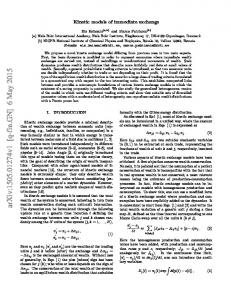
B. Protocol for EV communication The communication protocol was construed considering the CAN bus specification. The structure of a CAN2.0A message has an identifier of 11bit (CAN2.0B 29bit) length and a data package of maximum 64bit.
7
ACK
EOF
ACK-Slot ACK-delimiter
End-Of-Frame
3…bit bus idle
Inter-framespace
2
CRC
CRC delimiter
15+1
data
CRC
0… 64
RTR
6 control
Identifier
(29) 11+1 arbitration
0 to 8bytes
CAN DATA FRAME (CAN 2.0A)
IDE, R1, DLC
TABLE I.
SOF
In “Table II” an example is shown for the parameter SOC, which is also marked in “Fig. 5”.
REALISATION OF COMMUNICATION
A. Introduction For a solution to a communication system between an EV and a charging point a hardware apparatus in the form of an electronic device and a protocol that fulfils the requirements were designed. To realise the communication, the communication pin of the power plug is used with a CAN (controller area network) bus as wired communication. The benefits are the simple realisation, connection stability and presence in the automobile sector.
1
Figure 5. Structure of the communication protocol considered on the CAN bus
With the 11bit identifier a protocol structure was defined, see “Fig. 5”. The first three bits are used to identify the source of the message, the following 4 bits define the component group and the last four bits the exact parameter.
PARAMETER DISCRIBED IN PROTOCOL
Example of a parameter from the protocol CAN-ID ParaSpecification Unit in dec meter 565 SOC state of charge [%] (EV - BMS SOC) CAN-ID in hex
DATA in hex
Example DATA in dec
235
26AC
9900
Factor 10-2
DATA in dec * factor 99,00
Format 8 byte HEX
End Value with Unit 99,00 %
In the protocol all parameters of the communication participants are described and have a unique ID. Also, the protocol gives enough space for future parameters that can be implemented in the structure. The protocol itself is independent of the communication technologies. The message includes the identifier and the data package. The identifier includes the information to interpret the data package. C.
Test construction for EV communication Test communication lines were built to construct the communication unit with the implemented protocol. The sketch of the test setup can be seen in “Fig. 5”. The communication path is a battery with a monitoring electronic unit, two communication units which represent the EV and the charging point, and two computers that are each connected to one of the communication units.
The communication unit (4) reads the data from the battery management system and the implemented software in the microcontroller converts the values into the protocol. The communication unit sends the data to PC 1 (1) and via CAN bus through the EV power cable (6) to (7) to the second communication board. PC 2 has a user application installed that works with the transferred values. The communication unit has to be configured once for the specification of the EV. Once installed the unit converts the needed parameters and provides them for further tasks or communication. Figure 6. Structure of the communication protocol considered on the CAN bus
Components in “Fig. 5”and “Fig. 6”are: • (1) • • •
• •
PC 1 with terminal software to display the received data (2) PC 2 with software application for user interaction (3) battery with integrated monitoring electronic unit (4) designed electronic unit with an 8bit micro controller and various interfaces to read data from battery monitoring electronic unit, convert data in protocol and transmit through CAN bus through EV power plug (5) second electronic unit with 8bit micro controller to receive data and communicate with PC 2 via software (6)-(7) communication path through cable fittings of standard IEC-62196-2
IV.
CONCLUSIONS
There is no standard defined for the communication between electric mobility participants. This paper presents one of the possible solutions for data exchange between the electric vehicle and charging point based on existing communication technologies. The example realization of the connection structure as well as the implementation of information flow between the units is proposed. In the context of V2G (vehicle to grid) the communication among the participants is necessary and can be realised by an extra device that would convert the needed values into a communication protocol. During the development of the system the main task of EV which is essentially to ensure mobility of the users can not be forgotten. The presented solution for a physical connection and protocol proposal for data exchange between electric vehicle and charging point was realized in the laboratory environment. A prototype of the realization in the field, installation of the devices in an available electric car and charging point, as well as tests and analyses are planned. REFERENCES [1]
Figure 7. Structure of the communication protocol considered on the CAN bus
M. Mohammadi, L. Lampe, M. Lok, S. Mirabbasi, M. Mirvakili, R. Rosales and P. van Veen, “Measurement Study and Transmission for In-vehicle Power Line Communication”, Telecomunications Jurnal of Austrlia v.°59/1, 2009 [2] M.Dennis and B. Thompson, “vehicle to grid using broadband communication”, Telecomunications Jurnal of Austrlia v°59/1, 02/2009 [3] M. Dennis and H. M. Jones, “Broadband communication enables sustainable energy services”, Telecommunications Journal of Australia v°57/2-3, 12/2007 [4] K. Borgeest, “Elektronik in der Fahrzeugtechnik”, vieweg, 2008. [5] A. Meroth and B. Tolg, “Infotainmentsysteme im Kraftfahrzeug”, vieweg, 2008. [6] K. Reif, “Automobilelektronik”, vieweg, 2006. [7] G. Schnell and B. Wiedemann, “Bussysteme in derAutomatisierungsund Prozesstechnik”, vieweg, 2006. [8] H. Wallentowitz and K. Reif, “Handbuch Kraftfahrzeugelektronik”, vieweg, 2006. [9] R. Walter, “AVR Mikrocontroller Lehrbuch”, Mundschenk Druck+Medien, 2004. [10] C. Wenge, G. Heideck and Z. Styczynski, “Stromversorgungseinrichtung für Elektro-Straßenfahrzeuge an der Otto-von-Guericke-Universität Magdeburg”, Power & Energy Summer Summit 2009, IEEE Studentbranch Ilmenau, 09/2009