Online PDF Computational Morphologies: Design Rules Between Organic Models and .... digital technology, computer-aided d
and a Hungarian language technology company (MorphoLogic) have initi- ated a project .... script instead of the Cyrillic orthography of the language. However ...
52. MATERIALS. 51. ACADIA 2013 ADAPTIVE ARCHITECTURE ... Newcastle University ... produced architecture, which would potentially behave as an adaptive organism. ..... Processing as a list of three-dimensional positions, which were.
wafer and large-scale arrays of motorized wheels transporint cardboard boxes. The Modular Distributed Manipu- lator System (MDMS) is such a large-scale ...
In this view, the simulation ends as soon as the design of the artifact is ... be evolutionary algorithms [5], analogy [6], constraint satisfaction [7], shape .... The "lives" of the agents are divided into time-steps, and a simulation is run for ...
the centre of the North American discussion for the. âtransplantâ of the âmodelâ to US ...... our research group is following, but research is just in the beginning.
Industries, November 1998, p.43-43; Automotive News, 29. March 1999, p.24j. There was also a discussion amongst. UAW (United Auto Workers, the US automobile trade union) ...... Automotive Industry, Oxford, Said Business School,.
of interconnected neurons specifying each neural module. 2.1 Neural .... Fig.10. The Retina module contains two output ports, dp and ap, for disparity and.
Neural modules in NSL are hierarchically organized in a tree structure where a .... Fig.10. The Retina module contains two output ports, dp and ap, for disparity ...
Modular Inspection Equipment Design for Modular Structured. Mechatronic Products â Model Based Systems Engineering. Approach for an Integrative Product ...
May 25, 2016 - Modular and Supramolecular Approach ... 1 Physical Chemistry and Soft Matter, Wageningen University & Research, Wageningen, The Netherlands, ...... (PDF). Acknowledgments. The authors thank Huib J. Croes for ...
Jul 6, 2005 - ISBN 951-22-7767-0 (PDF). ISSN 1795-2239. ISSN 1795-4584 (PDF) .... Agency2) funded project on product development and concepting in ...
Aug 12, 2005 - The gaps were identified through application of three ... These tools add to the modular platform development process by filling in the gaps ...
Oct 7, 2016 - Chalmers University of Technology and University of Gothenburg ..... The specific element weight w(Ï, θ) is set to be 0.1 and 0.7 if there is a house. 10 ..... Glowinski, R., Pan, T. W., Hesla, T. I., Joseph, D. D., Periaux, J., 2001.
Oct 25, 2016 - Essa classe de materiais apresenta comportamento interessante ... materiais, quando tracionados expandem-se transversalmente e quando ...
pressure head (Q vs H) and flow rate vs net positive suction head (Q vs NPSH) for this rotational velocity (figure 4) were determined by the affinity laws of ...
Acknowledgements. This thesis would never have been possible without the help of many people. .... Divisor sums, partition numbers. 2. Traces of ... defined over a number field has complex multiplication (sometimes abbreviated as CM). ...... [âm](â
Jan 23, 2014 - relationship with the strain or stress of aramid fibers [15], as shown in Figure 4(b). Therefore, it is a potential method of microscale experimental ...
3Dept. of Chemical and Biomolecular Engineering, Melbourne University, Melbourne, Victoria ... Multiphase Phenomena and CFD Modelling and Simulation.
gence algorithm for inverse problem of nanoscale semiconductor device is pre- sented. This approach ... mainly integrates the semiconductor process simulation, semiconductor device simulation, evolutionary ... 1 Introduction. Technology ...
Emile SCHEEPERS1, Markus A. REUTEr3 and Rob BOOM1,2. 1Dept. of Materials ..... Netherlands. CROSS M., EVANS J.W. and BAILEY C. (eds.), (2001),.
cannot assemble a custom rendering algorithm. ... the advantages and disadvantages of our approach, and state particular fields .... the proprietary software.
TIMSS and PIRLS. PIRLS/prePIRLS. TIMSS. Student Questionnaire. General
Module. √. √. √. Reading Module. √. √. Mathematics and Science Module. √.
article (e.g. in Word or Tex form) to their personal website or institutional repository. .... free energy, and introduced single mutations at five posi- tions. Although ...
Dec 3, 2014 - Modular Fibrous Morphologies: Computational Design, Simulation and Fabrication of Differentiated Fibre Composite Building Components.
Modular Fibrous Morphologies: Computational Design, Simulation and Fabrication of Differentiated Fibre Composite Building Components Stefana Parascho, Jan Knippers, Moritz Dörstelmann, Marshall Prado, and Achim Menges
Abstract The paper presents a bottom-up design process based on the transfer of biomimetic design principles and digital fabrication strategies for modular fibrebased structures, as demonstrated on a full-scale prototype pavilion. Following the analysis of the structural principles of the beetle elytra, the material differentiation and the morphologic principles of the biological role model are transferred into design and fabrication strategies. Simultaneously, developments of a coreless robotic winding method for glass and carbon fibre reinforced composite elements are incorporated into the design process. The computational set-up developed for the entire workflow is presented, showing the integration of structural analysis with digital simulation, which enables the automatic generation of the robotic winding syntax for individually differentiated components. The investigations, simulation, fabrication and assembly process, which led to the realisation of a highly efficient lightweight architectural prototype, are explained in the current paper.
1 Introduction Traditionally, architectural design has been prevailed by top-down design methods, which usually subordinate material and fabrication considerations for apre-conceived geometry. While bottom-up strategies have been increasingly explored in design processes, as for example with biomimetic approaches, these are still often followed by a top-down fabrication solution. Contrary to conventional design methods, both the design development and the materialisation process can
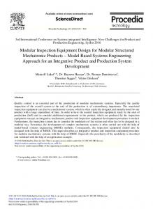
Fig. 1 ICD/ITKE Research Pavilion 2013–2014, top view
be regarded as equal design drivers through the use of biomimetic design principles and the simultaneous development of novel fabrication methods (La Magna et al. 2013; Menges 2013) (Fig. 1). Biomimetic approaches have proved to have significant potential for design implementations through their systemic complexity and manifold logics (Gruber 2011). Morphological principles of natural organisms are abstracted and transferred into architectural applications for their performative geometries and functional integration. Biological evolutionary processes offer a remarkable example for the integration of multiple requirements into the morphogenetic process. As observed by biological research, natural systems do not evolve as singular optimisation solutions, but rather negotiate between numerous and often conflicting factors, providing a compromise that can fulfil a multitude of requirements, contrary to conventional optimisation procedures (Knippers and Speck 2012). Similarly, advancements in fabrication methods have led to a constant growth of the geometric design space for architectural applications but rarely to new systems beyond existing typologies of building construction. The development of fabrication strategies based on material behaviour allows an early integration of manufacturing logics into the design process and an exploration of novel structural typologies (Pottmann 2013). The ICD/ITKE Research Pavilion 2013/2014 presents a design approach based on multiple, concurrent bottom-up investigations, illustrating how parallel research of both biomimetic principles and novel fabrication techniques lead to a highly integrative design process. Biological principles, material properties, structural performance and fabrication constraints are translated into parameters of architectural morphology, allowing the development of a computational design setup as a point of confluence.
Modular Fibrous Morphologies
31
2 Context The presented project builds on previous research conducted by the authors, through the collaboration of the Institute for Computational Design and the Institute of Building Structures and Structural Design which focuses on integrative design methods and their application in architecture, tested and implemented in full scale prototypical research pavilions. The research conducted at ICD/ITKE concentrates on design processes that incorporate biomimetic investigations as a design input from natural systems providing morphological as well as process logics for the fabrication of efficient lightweight structures. The Research Pavilion 2011 represented a direct application of biomimetic design strategies into a built architectural prototype. The morphology is derived from the structural and connection principles found in the Echinoides’ plate arrangement, which led to a remarkable structural performance of the system (Schwinn et al. 2013). The Research Pavilion 2012 focused on the scale of material arrangement, providing differentiated stiffness and strength through the variation of fibre disposition, as found in many biological fibre-based systems like the exoskeletons of arthropods (Reichert et al. 2014). In order to implement biological principles of fibre-based systems, composite materials such as fibre-reinforced polymers (FRP) are used to locally differentiate material properties through position, orientation, density and type of fibres (i.e. glass or carbon) in order to enhance the structural performance of the system. FRPs are widely used in industrial applications such as the aerospace industry, due to their high strength to weight ratio and unrestrained mouldability. Standard fabrication techniques rely on the manual or automated application of fibres to pre-fabricated formwork, constraining the otherwise formable material to a logic of serial production or the use of adaptable moulds for niche markets. Neither of these seems suitable for unique large-scale architectural applications; therefore the development of a novel fabrication technique would be required for the production of freeform FRP building components of the lot size one. In the Research Pavilion 2012, a coreless winding technique was developed through robotic fabrication that allowed the generation of a complex double-curved monocoque shell without the need for a positive mould (Waimer et al. 2013). The formwork was replaced by a minimal steel frame, which enables double curved geometries to emerge through fibre-fibre interaction between the frame elements. In order to produce a single shell through a continuous winding sequence, an on-site fabrication method was developed through the use of a robotic winding set-up. The coreless winding approach reduces the fabrication effort, as it does not require the production of a positive mould; on the other hand, the analysis and simulation effort increases as the complexity of the system is influenced by the constantly changing stress in the fibres. Further challenges based on the previous research include the expansion of the geometric solution space by eliminating the limitations linked to the robotic set-up (Reichert et al. 2014) as well as improvements in transportability and
32
S. Parascho et al.
manufacturing logistics, both achievable through the use of a modular system. A further development of the coreless winding method allows the minimisation of the necessary formwork and the generation of an adaptable and reusable frame for a component-based system. On a structural level, the development of a double-layered system leads to an enhancement of the construction’s structural capacity.
3 Investigations 3.1 Bottom Up Biological Investigation The ICD/ITKE Research Pavilion 2013–2014 continues the successful series of multidisciplinary research projects through collaboration with biologists from Tübingen University and imaging specialists from the Karlsruhe Institute of Technology, resulting in an open-ended biomimetic bottom-up process. A strategic preselection of biological role models, which was based on natural lightweight fibre structures with specific features like material anisotropy, materialisation processes and resulting functional morphologies, preceded the project. The selected role models were investigated by interdisciplinary teams of architects, structural engineers and biologists. Throughout these investigations the natural fibre composite structure in the beetle Elytra, the protective shell of the abdomen and wings, provided a versatile role model for performative lightweight structures. The comparison of ground beetles and flying beetles revealed how the negotiation of antagonistic performance criteria, e.g. structural rigidity and weight reduction, within an evolutionary morphogenetic process led to the development of a multi-functional lightweight material system. The material efficiency of the system is based on anisotropic organisation of chitin fibre composite material which forms a double layered shell and is coupled by trabeculae, internal bracing structures (Fig. 2). The geometric articulation of this lightweight construction was studied through microcomputer tomographic scans which were conducted at the ANKA/Institute for photon science and synchrotron radiation and electron microscopy scans by the Department of Evolutionary Biology of Invertebrates in Tübingen. Both methodologies operate on different scales and provide various insights into the structure of the role model. While material organisation and fibre arrangements were analysed based on the 2d SEM scans (Fig. 2b), the micro CT scans were processed to very detailed 3d mesh data and allowed insight into the global as well as the internal structural morphology (Fig. 2a). Like the biological role models, which come in a wide variety of shapes and sizes, an extensive array of performative architectural forms, which follow these structuring principles and fabrication parameters, are possible. Comparative studies of eight flying beetle species allowed for the abstraction of the underlying functional principles. On the material scale, seamless structural integration of the upper and lower shell is achieved through continuous fibre
Modular Fibrous Morphologies
33
Fig. 2 Beetle elytron, (a) cross section Chrysomela (Top), Cassidia (Bottom), 3d model constructed from Micro CT data by Dr. Thomas Van de Kamp; (b) section through Trabecel, Leptinotarsa decimlineata, SEM scan by Prof. Oliver Betz
arrangements within each trabecula. Structural morphologic differentiation can be described on two levels; the local geometric articulation of each trabecula and their arrangement within the global structural system. A clear interdependency of loading situations and the respective morphologic response of the system was identified and abstracted through the description of geometric rules. These relations between structural capacity, fibre arrangements and geometric articulation were transferred into a component based lightweight construction system. The transfer into a technical application requires a level of abstraction, which allows the use of specific functional features without recreating the complexity of the entire natural role model. In the present case this becomes visible through the favouring of the advantages of a modular construction logic over the structural benefit of a seamless continuous shell.
3.2 Bottom Up Winding Process Investigation Parallel to biomimetic investigations in an integrated design process, extensive research on fabrication strategies explore geometric potentials inherent in a material system. This requires a further bottom up investigation of fibre winding techniques and their latent geometric possibilities. In a bottom-up fabrication process, material is not applied to a pre-defined form, but actively influences the design (Fleischmann et al. 2012), by defining the possible solution space and potential of the global design outcome. As a result, the developed geometry of the system and fabrication strategies are a direct
34
S. Parascho et al.
Fig. 3 Coreless winding; (a) two fibres connecting four non-planar points; (b) fibres deforming under the tension of subsequently wound fibres; (c, d) anticlastic curvature induced by helicoidal winding
consequence of material capacities, which requires a simultaneous development of both architectural morphology and fabrication. The geometry of the fibre-based elements is strongly defined by material properties since it is the result of the interaction between subsequently applied fibres. For the generation of the characteristic column-like structure found in the beetle elytra role model a coreless winding method was chosen and further developed, in order to continually minimise the necessary formwork for the production of double-curved FRP geometries. For the transfer of the trabeculae morphology into component geometry, fibres are helicoidally wound around the component frame, which is determined by an adaptive computational model allowing fabrication and material constraints to actively control the size, shape and typology. The resulting fibres form a double curved surface configuration (Fig. 3). The anticlastic geometry is the immediate result of the linear fibres being tensioned once a proper fibre bond is achieved through continuous subsequent winding of multiple fibre layers. With each winding step fibres are pressing on each other, requiring the material to constantly negotiate a state of equilibrium throughout the fabrication process. At the same time, the use of a robotic manufacturing method and the set-up of a parametric robotic code generation system enable the differentiation of each fibre layout. Through the sequential fibre-laying process both the geometry and the stress state of the fibres are constantly changing in a dynamic process, which leads to the necessity of a complex, constantly updating simulation process.
4 Integration and Verification 4.1 Integrative Design Tool The co-development of biomimetic insight, material experimentation and fabrication strategy is a reciprocal explorative process where new insight immediately affects the criteria of evaluation and direction of investigation for the adjacent fields. This initial intuition driven process needs to be formalised as the interrelated insight becomes more complex. Computational design strategies offer a suitable platform to
Modular Fibrous Morphologies
35
integrate and mediate between parallel bottom-up investigations, thus a meaningful synthesis is possible. The biomimetic investigation led to a structurally driven local geometric variation of the components and their global arrangement, while the investigation of fabrication techniques and material experimentation explored the achievable geometric solution space. These reciprocal investigations need to be mediated to find their confluence in the component geometry as well as the global design outcome. The biological input on the components geometry is to ensure a transfer of the role models structural capacity into the technical implementation of the abstracted principles. Not only local morphologic parameters like structural depth and component diameter are defined through geometric rules in response to loading conditions, but also global structural situations like cantilevering and internal wall structures are affected by biomimetic design principles. At the same time the specific robot set-up used for fabrication of the components sets geometric constraints, which are necessary to avoid collisions, or out of reach errors during the robotic winding process. The robot tool sets minimal angles between the polygon edges and defines how much non-planarity can be geometrically achieved. Equally important is the information of the geometry through material behaviour. The winding logic depends on certain geometric conditions to ensure fibre-fibre interaction, which is required to achieve a structurally stable laminate. Therefore the height to width ratio of the component and specific length ratios between neighbouring edges have to be ensured. This shows how each part of the project equally contributes to the integrated design process and potentially affects mayor spatial characteristic and ultimately the appearance of the global structure. To negotiate these various inputs onto the local and global geometry, a constraints-based modelling approach was utilised. In a first step, possible cell layouts are negotiated through a planar arrangement of cells with variable dimensions and numbers of edges. Biomimetic as well as structural principles are integrated achieving a more dense and stable structure at edges and bifurcating areas. The initial topological connections of the components are described as a particle-network, which can resolve into one of multiple possible states of equilibria. The initially defined constraints of various process parameters for the control of component geometry can be systematically described which allows an interaction within the constraint-based computational framework. This framework is hierarchically organised, therefore robotic fabrication constraints and material behaviour can set the absolute boundaries of the geometric range, while the biomimetically derived structural principles drive geometric differentiation within these boundaries. Through a first FE Simulation incorporated in the geometry generation tool, dimensions of the connecting members are optimised for structural performance. Global and local geometric characteristics are analysed and regulated within each iteration. This guarantees the greatest possible geometric adaptation while ensuring fabricability of each component. Parameters such as element thickness, out of plane maximum distance, component dimensions and angles
36
S. Parascho et al.
Fig. 4 Intermediate state of the computational form generating tool showing active parameters that are negotiated during the form finding process
as well as structural stability are translated into geometric factors and negotiated until a state of equilibrium is achieved (Fig. 4). Such a computational process of morphogenesis mediates various system influences and results in complex, emergent geometries, which are formed through system information rather than predetermined geometric solutions.
4.2 Material Behaviour Component geometries emerge through the tensioning of the subsequently wound fibres, inducing deformations as a consequence of the fibre-fibre interaction. The overall geometry is not pre-defined, but is rather the result of the fabrication process and material properties. Due to this form-finding process, the material assumes its own geometry, requiring an adaptive winding sequence, which takes into account structural and material constraints. As a result, a simulation of the winding process and the consequences on material behaviour was needed by developing formation rules for the generation of the hyperbolic geometry. In order to generate the robotic code and proper fibre composite structure for various differentiated components, a winding syntax – a systematic sequence of fibre winding – was developed. The generated FRP material system requires three different layers of fibres to be wound consecutively for the generation of a structural composite for the double curved components (Fig. 5). The first layer of glass fibre serves as form giving and defines the geometric features of the component, while the subsequent carbon fibre layers structurally reinforce both the component and the global geometry.
Simulating the behaviour of the material layout and subsequently developing the winding syntax requires defining a set of rules that outlines the constraints set by the system. These rules were generated from numerous hand winding tests, digital simulations and robotic test windings in order to set the geometric range of possibilities through the pursued robotic winding method. Parameters were developed and tested, such as topology and component dimensions, angles between edges and distance between inner and outer layer, maximum degree of non-planarity and opening degrees of the components, leading to a robust set of boundary conditions that implicitly define the range of the possible global geometric outcomes. The parametric set-up enables the automatic generation of the winding syntax for each component producing a polyline that represents the exact sequence for the generation of the robotic code. The main challenge for all winding layers is ensuring a proper fibre-to-fibre bond that generates a structurally performant hyperbolic geometry. The formdefining glass layer thus requires each subsequent fibre to tension the previous ones, stabilising the structure with each winding iteration. This is achieved through a fibre laying sequence that loops around the component frames and through the shifting of connection points until all fibres are tensioned (Fig. 6). The winding syntax for both carbon layers further ensures the fibre tensioning through the definition of the wrapping sequence. The first layer, which locally reinforces the component geometry, is based on a general set of rules adapted to
38
S. Parascho et al.
Fig. 7 Single component and fibre detail
each element, which allows for the differentiation of fibre density and efficient use of material while the second carbon fibre layer responds to global force distribution and component geometry (Fig. 7).
4.3 Structural Integration The geometric outcome is strongly informed by structural analysis data throughout the design process. In this type of integrated design process the structural analysis is used not only as a means of validation of the results, but is included as one of the design drivers on various scales. Structural considerations are partly derived from the biomimetic investigations, since the beetle elytron offers a number of structurally efficient morphological principles. The double-layered shell enhances the stability and structural performance compared to a single layered system. Simultaneously material investigations and Finite Element Analysis supply additional data that is transferred into design logics and embedded in an adaptive geometric generation process. On a material level, the fabrication method needs to ensure a strong fibre-to-fibre bond in order to achieve the necessary stiffness and resistance. Material performance can be programmed through the differentiation of the angle in which fibres intersect, leading to a variation from an anisotropic material behaviour for small angles to a quasi-isotropic behaviour for angles close to 90ı . The carbon fibre layers are specifically developed to structurally reinforce the individual components as well as the global form. The first carbon fibre layer locally reinforces the component geometry around the edge and allows forces to be transmitted in plane. The geometric configuration of this layer strongly depends on the component frame geometry requiring the integration of fabrication constraints and frame collision avoidance. Through this arrangement, the component’s edges are stiffened by generating a local structural height while enabling forces to be transferred throughout the element.
Modular Fibrous Morphologies
39
Fig. 8 (a) Model for FE Analysis; (b) resulting forces in component; (c) translation of forces into vectors; (d) fibres laid according to force vectors
Contrary to the first layer, the differentiated carbon fibre layer facilitates force transmission between the two structural layers and from component to component, taking into account global parameters such as neighbouring elements and connection points. Furthermore fibres are specifically placed to support the global structure where high forces emerge. For this purpose the global geometry is first analysed as a continuous shell (Fig. 8) with Finite Elements, and the resulting stress state is extracted from the analysis. This is translated into geometrical vectors in order to allow for an interchange between the different working environments. The strength and orientation of each force provide information about where the structure can be efficiently reinforced, enabling the generation of winding paths from the derived force vectors. Simultaneously, the resulting winding paths are informed by the general fabrication logic, ensuring that only feasible winding paths are generated. The density of these additional fibres is varied depending on the strength of the forces, leading to an individual fibre layout for each component that altogether forms a global structurally active construction.
5 Realisation 5.1 Fabrication Set-up One goal of this research was to develop a fabrication system with a broad range of geometric freedom for the materialisation of fibre composite structures in architectural applications. The fabrication set-up, which continuously develops throughout the research, therefore becomes an integral constituent of the design and materialisation process of complex, distinct fibre composite geometries. The set-up used for the fabrication of the FRP components relies on two synchronised 6-axis industrial robots, each holding an adaptable steel frame that defines the two boundary polygons of the components. The fibres are wound around
40
S. Parascho et al.
Fig. 9 Fabrication set-up
the control points of the effectors through the parallel movement of the two robots while the fibre source and resin bath are stationary (Fig. 9). Defining a fabrication system for non-standardised components presents several unique challenges. Namely, providing an adaptive framework with a high level of geometric flexibility, which subsequently must maintain the rigidity necessary for winding tensioned fibres; while minimising the materials and complexity required by the use of a standardised kit-of-parts. Each component is defined digitally by a set of two non-planar closed polygons containing 4–7 vertices each. Each vertex has 8 degrees of freedom (Fig. 10), which defines the frame geometry upon which the fibre composite material is wrapped. In total each component requires the definition of 64–112 variables to entirely constrain the wrapping frame. To minimise the complexity of the system that would be required, industrial robots are used which provide precise control of 6 degrees of freedom per vertex (i.e. x, y, z position and a, b, c rotation). Through a robotically assisted assembly process, vertices of the component polygons are defined in reference to the orientation of the robotic end effector. Adjustable stands are attached to the effector manually, which physically describe the component geometry. Tolerances are determined by the precision of the robot rather than the manual procedures. Milled guides control the two remaining variables including: the inaxis rotation and alignment of the frame segments (Fig. 10). This assembly system minimises material use and complexity of parts by embedding multiple fabrication constraint into a single construction guide while providing a high degree of reconfigurability by employing the inherent flexibility in a robotic set-up.
Modular Fibrous Morphologies
41
Fig. 10 Diagram of adjustable effector stand and milled guides that define component vertices
The use of two corresponding robots benefits the fabrication process in several ways. Both robots, each with an attached reconfigurable frame, function as one cooperative robotic system. This enables the robotic movements to be synchronised, maintaining the relative frame orientation without the need for interstitial structure, which could possibly obstruct the winding process. The two robots can also equally divide the dead loads placed on the system and resist tensile stresses accrued by sequentially tensioning the fibres. Feedback from integrated sensors in a robotic system allows for adaptive control to compensation for accumulated geometric inaccuracies. As a result, large-scale fabrication of component geometries, which includes smaller tolerances for inter-component connections, higher tensioning of fibres for structural composites and error correction throughout the winding process, become systematically possible.
5.2 Results The presented integrative design process, based on the two bottom-up investigations, resulted in a full-scale prototype, built at the *****. The pavilion consists of 36 individually shaped components that are assembled into a highly material efficient construction system. Through the use of automated robotic fabrication, a high
42
S. Parascho et al.
Fig. 11 Assembly setup; lightweight and stability of the pavilion
degree of geometric freedom was achieved, resulting in differentiated diameters, thicknesses, non-planarity and number of control vertices. The components ranged in size from 50 to 250 cm in diameter. The lightweight performance of the construction is illustrated through the minimal weight of the prototype, with a total weight of 593 kg of 58 km of glass fibres and 44 km of carbon fibre as well as the related polymer matrix. The individual components weigh between 11.5 and 24.1 kg, and can thus be easily lifted into place by one or two people, allowing for a simple and fast assembly process (Fig. 11). The pavilion consists of a double layer fibre composite shell, which encloses an area of 50 m2 . The system bifurcates creating an internal structural wall, a principle derived from the biological role model, which divides the space and creates two openings facing the university and the surrounding park. The pavilion demonstrates the potential of fibre composites for lightweight construction through the stability and efficiency of the structure and illustrates the biologically abstracted principles, from material organisation, i.e. the fibre arrangements, to the structural capacity of the overall construction. The custom development of fabrication methods and the integration of material, fabrication, biomimetics and structural analysis into one multi-informed design process, allowed the development of new types of architectural geometry and related novel spatial qualities, as well as the detachment from existing building types and structural typologies. The overall form, spatial arrangement and material expression contribute to a unique architectural experience while at the same time being extremely efficient with employed material resources (Fig. 12).
Modular Fibrous Morphologies
43
Fig. 12 Various components assembled
Conclusion The presented research successfully integrates both bottom-up explorations, on a biological level as well as on a material and fabrication level, into a coherent and highly integrative design process. The numerous influencing factors were translated through computation into a common geometric language and could thus be simultaneously considered throughout the design process. At the same time each parameter strongly affected the geometric outcome widening or limiting the solution space. The use of FRPs and individually adaptable fibre placement enabled a straightforward production of numerous individual geometrically complex but material efficient elements, which was facilitated by the development of a robust computational set-up that allowed an effortless transition from the design intention to the robotic winding code and production. The biomimetic investigation provided numerous morphological principles that primary defined the components geometries. Furthermore it supplied structurally efficient spatial arrangements that increased the geometrical complexity of the global construct. (continued)
44
S. Parascho et al.
Through the development of a modular system, the dimension of the resulting structure was no longer limited to the robot reach, which demonstrates how the core-less winding method is applicable in large scale building implementations. In addition the geometric complexity of the global structure was no longer limited by the robotic space, allowing spatial structures such as the internal wall and higher freedom in the global topology of the structure. Future research is currently concentrating on the further integration between the structural, geometrical and morphological features of the built prototypes. As the core-less winding approach has proved to be extremely efficient for the fabrication of large scale and custom components, further reducing the requirement of formwork elements is currently under investigation. Finally, the biomimetic approach may offer interesting developments, which may open future perspectives in the design and implementation of innovative structural systems (Fig. 13).
Fig. 13 ICD/ITKE Research Pavilion 2013–2014
Acknowledgements This project was possible only through the work of the students participating in the “Fibrous Morphologies” Studio 2012 from the University of Stuttgart, especially Leyla Yunis and Ondrej Kyjanek, as well as the collaboration on structural issues with Vassilios Kirtzakis.
Modular Fibrous Morphologies
45
References Fleischmann, M., Knippers, J., Lienhard, J., Menges, A., Schleicher, S.: Material behaviour: embedding physical properties in computational design processes. Archit. Des. 82(2), 44–51 (2012) Gruber, P.: Biomimetics – Materials, Structures and Processes Examples, Ideas and Case Studies. Springer, Berlin/New York (2011) Knippers, J., Speck, T.: Design and construction principles in nature and architecture. Bioinspir. Biomim. 7, 015002 (2012) La Magna, R., Gabler, M., Reichert, S., Schwinn, T., Waimer, F., Menges, A., Knippers, J.: From nature to fabrication: biomimetic design principles for the production of complex spatial structures. Int. J. Space Struct. 28(1), 27–39 (2013) Menges, A.: Integral formation and materialization: computational form and material gestalt. In: Manufacturing Material Effects: Rethinking Design and Making in Architecture. Routledge, New York (2013) Pottmann, H.: Architectural geometry and fabrication-aware design. Nexus Netw. J. 15(2), 195– 208 (2013). doi:10.1007/s00004-013-0149-5 Reichert, S., Schwinn, T., La Magna, R., Waimer, F., Knippers, J., Menges, A.: Fibrous structures: an integrative approach to design computation, simulation and fabrication for lightweight, glass and carbon fibre composite structures in architecture based on biomimetic design principles. Comput. Aided Des. 52, 27–39 (2014) Schwinn, T., Krieg, O., Menges, A.: Robotically fabricated wood plate morphologies. In: Brell-Çokcan, S., Braumann, J. (eds.) Rob j Arch 2012 SE - 4, pp. 48–61. Springer, Vienna (2013) Waimer, F., La Magna, R., Knippers, J.: Integrative numerical techniques for fibre reinforced polymers – forming process and analysis of differentiated anisotropy. J. Int. Assoc. Shell Spat. Struct. 54(178), 301–309 (2013)


![[EPub Download] Computational Morphologies: Design ... - Google Sites](https://m.moam.info/img/260x300/epub-download-computational-morphologies-design-go_64773a44097c474e708b77eb.jpg)