KWON_LAYOUT.qxp_Author Layout 1/30/15 1:53 PM Page 136
OPTICAL COMMUNICATIONS
Modulation and Coding for Dimmable Visible Light Communication Sang Hyun Lee, Sung-Yoon Jung, and Jae Kyun Kwon
ABSTRACT The recent interest in short-range optical wireless communication technology driven by the widespread deployment of solid state lighting has led to significant efforts on the standardization of visible light communication. In such efforts, the consideration of dimming support poses fundamental challenges on the VLC system design that have not been addressed elsewhere. This article overviews the technical considerations for enhancing the VLC physical layer by summarizing the state-of-the-art advancements in modulation and coding technologies dedicated to VLC systems. In addition, the technical challenges for system enhancement under lighting restrictions are described.
INTRODUCTION
Sang Hyun Lee is with Sejong University. Sung-Yoon Jung and Jae Kyun Kwon are with Yeungnam University.
136
Short-range wireless technology has recently been a key driver leading the surge of deployment for wireless personal area networks based on wireless standards such as the IEEE 802.15 series of standards. As a viable candidate for enabling technologies, visibile light communication (VLC) technology using light emitting diodes (LEDs) [1–3] has captured the interest of academia and industry due to the widespread transition from incandescent/fluorescent lighting to energy-efficient solid-state lighting. The fast switching control feature of LEDs enables the use of devices for lighting purposes in data transmission through the visible light spectrum as shown in Fig. 1. VLC conveys information by modulating the intensity of light emitted from LEDs at a rate faster than human perception. VLC can offer data rates in the megabits per second range over short distances in the visible light spectrum, where low-cost optical sources are readily available, and the best performance is obtained using a cost-efficient arrangement implemented with only LEDs and photodiodes (PDs). Two main obstacles for VLC physical (PHY) layer design in achieving high-rate transmission are flicker and dimming [4]. Flicker, fluctuation of the brightness of light in the course of modulating information into light sources, can have an adverse effect on human physiology. Therefore, the design of modulation techniques requires meticulous care to avoid noticeable flickering
0163-6804/15/$25.00 © 2015 IEEE
during communication. The support of dimming is another major feature, in which a VLC device is equipped for the main functionality of lighting. This requirement stems externally from users who can dim the light intensity over all ranges from off to full, and proper VLC operation under arbitrary dimming is strongly recommended. Considerable efforts have been made to produce the technical specifications in IEEE 802.15.7, which realizes high-data-rate compatibility and cost effectiveness based on the consideration of flicker and dimming. To act in concert with the expansion of the technology and the demands for a higher data rate, the future enhancement of standard systems is an important target. To meet regulatory requirements and enhance system performance, some potentials for modification are presented from the perspective of the PHY design for existing systems. This article discusses the benefits, potentials, and challenges associated with the use of various modulation and coding techniques as well as their advantages in dimming support. The essential characteristics, such as optical transmission/reception and LED physical characteristics, are also considered to ensure effective operation with dimming support, and the specific technologies of several efforts to overcome them are reviewed. In addition, the challenges ahead in terms of the technical issues and regulations are addressed.
VLC TRANSMISSION WITH DIMMING SUPPORT Data transmission in VLC is carried out by conveying information through temporal intensity changes in the optical pulse. The modulation and demodulation proceed with intensity modulation (IM) and direct detection (DD), respectively. In IM, the LED emits pulses at different intensity levels according to different electrical digital message symbols in the wireless link. As VLC transmitters are mostly intended for whitecolor lighting, they are implemented with either a single phosphor-converted (PC) white LED, generated using blue LEDs with yellow phosphor, or a combination of multicolored LEDs such as red-green-blue (RGB). If a single type of
IEEE Communications Magazine • February 2015
KWON_LAYOUT.qxp_Author Layout 1/30/15 1:53 PM Page 137
Some message information cannot be transmitted, or the resulting rate is G
R
1 0 0 1 0 0 1 1 1 WDM 0 1 0 CIM 1 1 0 1 1 0 1 1 0
R
G
B
reduced compared to the maximum MIMO interference management positioning multiple access
1 VLC with 0 dimming support 1 0 1 1 1
possible rate. Both are undesirable for enhancing the data rate of VLC. Hence, dimming support
B
challenges us to discover how to handle this inconsistency, which has not been considered in other
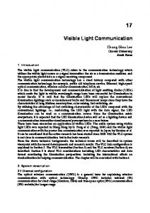
Figure 1. Configurations of VLC. VLC can be configured in various ways according to the configuration of the LED lamps: a single data stream transmission via a single PC LED, multiple data stream transmission via an array of RGB LEDs, and so on. LED is used to produce white-color emissions for reduced cost, only a single data stream can be transmitted, thereby exploiting a single degree of freedom in the communication link. The PD detector performs DD of the intensity signal by inducing the electrical photocurrent proportional to the received optical intensity (square law). Since VLC receivers sense the intensity of the optical signal, the demodulation is inherently non-coherent. The main impairments for DD include shot noises induced by the signal and ambient light, and the pre-amplifier noise encountered at the receiver [1]. If the ambient shot noise and pre-amplifier noise become dominant in the optical wireless links, the channel response for VLC is well approximated by the additive Gaussian noise model [5, 6]. For the dimming feature, the radiant intensity of a light source is defined as the optical power emitted per solid angle. The extent of dimming can generally be measured from the average intensity of the optical signal. The physical characteristics of the optical intensity channel impose a peak optical power constraint to prevent LED failure and to secure eye safety, equivalently viewed as constraints on peak signal intensity. The demodulation that detects the normalized power stipulates that the transmitted signal always has a non-negative signal level. In addition, physiological safety regulations along with dimming support place a limit on the average emitted signal level. Under the maximum level constraint, the capacity of the optical Gaussian noise channel is finite, and reliable communication can be achieved using two-level modulation techniques, albeit requiring exponential spectrum use [7]. The range of signal intensities can be represented in a normalized region of [0,1], where zero and one correspond to the off and full levels of intensity, respectively. The intensity of the optical signal conveying a uniform message gives
IEEE Communications Magazine • February 2015
communication systems.
rise to 50 percent (or 1/2) dimming on average. The human eye normally perceives the average illuminance instead of the instantaneous changes if the intensity changes faster than 150–200 Hz. Thus, VLC systems are designed to modulate the signal optically such that the intensity varies at a frequency higher than the inverse of the maximum flickering time period (MFTP) [4], in which the human eye cannot perceive the temporal change. Let d Œ [0,1] be the average ratio of the duration of the optical emission to that of the message data frame. This characterizes the dimming target of the VLC system. If the dimming target is set to 100d percent, the time-averaged intensity should be equal to 100d percent within an MFTP. The dimming target associated with d 0.5 may require non-uniform signal levels in the data frame, resulting in non-uniform frequencies of message symbols. Therefore, some message information cannot be transmitted, or the resulting rate is reduced compared to the maximum possible rate. Both are undesirable for enhancing the data rate of VLC. Hence, dimming support challenges us to discover how to handle this inconsistency, which has not been considered in other communication systems. This article provides an overview of modulation and coding techniques developed for this purpose.
MODULATION FOR DIMMABLE VLC ONE-DIMENSIONAL MODULATION TECHNIQUES Modulation techniques to remedy the above challenges are classified into two categories, which are referred to as the time-domain approach and the intensity-domain approach. The time-domain approach adds compensation symbols of two levels (ON and OFF) within an MFTP to match the dimming target, whereas the intensity-domain approach changes either the intensity levels or frequencies of occurrence for
137
KWON_LAYOUT.qxp_Author Layout 1/30/15 1:53 PM Page 138
These time-domain
Dimming 75%
Dimming 50%
approaches are simple to implement but do not allow
(a)
(b)
high data-rate
Dimming 75%
support because of bandwidth wastage (c)
by the compensation time intervals.
Dimming 75%
This limitation becomes severe as
(d)
the dimming target Dimming 75%
deviates from 50 percent. (e)
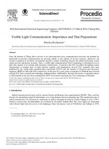
Figure 2. Examples of dimming support in binary modulations for VLC. Message symbols are normally given uniform probability. Four different types of methods can be used to offer dimming support with message symbols: a) original signal; b) intra-pulse insertion adds a compensation symbol to every message symbol; c) inter-pulse padding attaches a series of compensation symbols next to a series of message symbols; d) bias scaling changes the DC bias such that the time-averaged intensity is equal to the dimming target; e) distribution-adaptation maps a sequence of message symbols into another sequence of symbols of which the occurrence of ones and zeros adapts to the dimming target.
the message symbols. The time-domain approach is then classified into intra-pulse insertion and inter-pulse padding according to the position at which the dimming compensation symbols are placed in the data frame. Also, the intensitydomain approach includes bias scaling and distribution adaptation. The former alters the DC bias level by scaling the spacing between the intensity levels, and the latter adjusts the average frequency of the intensity levels that occur in an MFTP. This article focuses on each of these approaches. The intra-pulse insertion (shown in Fig. 2b) places the compensation symbols into an optical pulse to match the overall dimming in an MFTP. This can be viewed as pulse-widthmodulation (PWM)-based dimming control, in that the duty cycle of the optical pulse varies with the dimming target. For example, to meet a target of 75 percent dimming, the transmission of the ON and OFF binary message symbols with uniform probability is followed by ON compensation symbols, which convey no message, of the same duration. In Fig. 2b, an ON level of the same width is inserted into each pulse. This can be extended to more sophisticated techniques, such as pulse-amplitude modulation (PAM) and orthogonal frequency-division multiplexing (OFDM) [8]. A message is first modulated using those modulations, and the resulting optical pulse width is adjusted like PWM to match the dimming target. Variable pulse-position modulation (VPPM) [4], a variation of PWM-based dimming-supporting modulation, uses PPM for modulation of the message and PWM for adaptation to the dimming target, respectively. In the PWM-based dimming control, optical pulses
138
should be emitted for a very short period to provide support for sufficient resolution of dimming targets. However, VLC systems are normally subject to a limit on the minimum pulse width. This results in a restriction of the symbol duration, which in turn limits the data rate. Interpulse padding (shown in Fig. 2c) appends a compensation symbol interval to a message symbol interval. The message symbols are arranged to match the 50 percent dimming, and the compensation symbols conveying no information are added with the appropriate ON/OFF symbol proportion associated with the dimming target. The OOK-based mode (time-multiplexed OOK) [4, 9], specified in the IEEE 802.15.7 standard, uses this technique. These time-domain approaches are simple to implement but do not allow high data rate support because of bandwidth wastage by the compensation time intervals. This limitation becomes severe as the dimming target deviates from 50 percent (e.g., for a 10 percent dimming target, four times longer time durations are spent for compensation than the message). The intensity-domain approach, however, has an advantage in terms of the data rate over the time-domain approach. The bias scaling (shown in Fig. 2d) adjusts the DC bias and scales message symbols for dimming support. The DC bias associated with 50 percent dimming is initially set with the assumption of uniform symbol probability. If the dimming target is 75 percent, as shown in Fig. 2d, the DC bias is raised such that the intensity of the OFF symbol increases to the DC bias corresponding to 50 percent, whereas the ON symbol remains at the same level. On the other hand, for a 25 percent dimming target,
IEEE Communications Magazine • February 2015
KWON_LAYOUT.qxp_Author Layout 1/30/15 1:53 PM Page 139
the ON symbol decreases to the DC bias corresponding to 50 percent, and the OFF symbol remains constant. Therefore, the spacing between the ON and OFF symbols shrinks by half. This method can also be viewed as analog dimming. Although this is computationally simple, some technical difficulties emerge by nonlinear LED emission control and significant performance degradation due to the level spacing reduction. Distribution adaptation (shown in Fig. 2e) adjusts the frequency of the symbol levels such that the expectation of the resulting level distribution matches the dimming target. If the dimming target is 100d percent in the binary OOK modulation, the corresponding frequencies of the ON and OFF symbol should be d and 1 – d, respectively. Thus, the message symbols with uniform probability need to be represented in binary intensity levels with non-uniform probability. This conversion is achieved via a decoding process related to lossless compression, such as inverse source coding (ISC) [10]. It is noticeable that the ISC yields the best achievable limit for maximally distinguishable messages and is very efficient for the extreme dimming target ranges in a low-noise environment. Multi-level modulation can exploit several advantages of the intensity-domain approach in modulating the message on the intensity level of the symbol. Although binary modulation is a simple practical modulation technique, it allows a limited range of data rate improvement within finitely band-limited environments. Compared to high-bandwidth systems where binary techniques are found practical, low-bandwidth systems require multi-level modulations. Since multilevel modulations achieve reliable communication in band-limited VLC channels [11], a more practical choice for data rate enhancement is PAM. For PAM configurations with restrictions on the peak and average intensity, the capacityachieving message distribution under a Gaussian noise channel is discrete with a finite number of intensity levels [12]. Although such a distribution can be determined, the design of the transmission technique that conveys the message according to that distribution is still a challenge with a lack of modulation techniques with non-uniform symbol frequencies. In an effort to handle this challenge, a rate-efficient multi-level modulation with arbitrary dimming support has been developed based on a distribution-adaptation method [13]. A convex optimization formulation is developed with the objective of maximizing the data rate with respect to the intensity level distribution, and its closed-form solution is obtained. The resulting distribution can be realized using superposition or concatenation coding schemes. Multiple-subcarrier modulation (MSM) [14], implemented via OFDM, uses all the above methods for dimming support. OFDM conveys independent symbols with different subcarriers that can be separated orthogonally. Since the signal level of an OFDM signal can be negative, two different techniques of generating non-negative symbols suitable for IM have been proposed: DC-biased optical OFDM (DCO-OFDM) [2] and asymmetrically clipped optical OFDM (ACO-OFDM) [15]. DCO-OFDM uses the DC bias to yield a non-negative signal, whereas
IEEE Communications Magazine • February 2015
ACO-OFDM clips all negative levels to zero by electrical signal processing. Both techniques can accommodate all dimming methods except for distribution adaptation because an instantaneous signal level within a single OFDM symbol is hard to control by adjusting the signal level of individual subcarriers. The MSM technique realized by OFDM in general can offer a way of mitigating the fading effects caused by propagation environments (delay spread [14], atmospheric turbulence [16], etc.). However, this technique has several shortcomings for VLC systems. In IM/DD-based intensity-modulated techniques, due to the square law resulting from the power detection in optical-to-electrical conversion, an optical signal of a longer symbol duration undergoes higher noise corruption than that of a shorter symbol duration with the same amount of message information and electrical energy consumption. Since OFDM spreads time-domain symbols of short time duration along the frequency domain with a long time duration, the associated MSM may have lower power efficiency than single-carrier approaches. The signal clipping and nonlinear LED characteristics impair the orthogonality among subcarrier channels, thereby incurring inter-subcarrier interference. Furthermore, MSM does not yield an increase in transmission efficiency and has the same data rate as a single-carrier approach because only half of the subcarriers are used to guarantee non-negative real-valued optical output. Table 1 gives a brief summary of the properties of the above methods. Some properties incur technical challenges in system design: Lowcomplexity design and stable lighting support are the core issues handled from the implementation’s perspective. The consideration of signal shaping and transmission capacity in a noisy channel environment are also key issues for rate/energy-saving enhancement. Color temperature shift emerges as another critical implementation issue. This variation of the LED output color originates from the changes in two factors: optical intensity level and operating temperature of the LED. Different intensity levels can be observed in slightly different colors. Therefore, multiple-level modulations are more susceptible to this color change than binary modulations. On the other hand, an increase in optical power consumption causes a temperature rise, which shifts the wavelength of the LED emission. Since power consumption varies with the dimming target, all the modulation techniques may be subject to this type of color shift.
A multidimensional arrangement comprising multiple LEDs can be used for VLC. The intensity signals emitted from different LEDs are controlled to allow multiple-data-stream transmission under certain lighting requirements.
MULTIDIMENSIONAL MODULATION TECHNIQUES A multidimensional arrangement comprising multiple LEDs can be used for VLC. The intensity signals emitted from different LEDs are controlled to allow multiple-data-stream transmission under certain lighting requirements. There are two multidimensional configurations arranged with multiple LEDs of different colors integrated in a single position or multiple LEDs located at separate positions. If M groups of LEDs with C different colors are placed at different positions, the resulting degree of freedom is CM, and as many links are ideally available.
139
KWON_LAYOUT.qxp_Author Layout 1/30/15 1:54 PM Page 140
Timedomain approach
Intensitydomain approach
Noiseless channel
Noisy channel
Extreme dimming
Complexity
Channel/ line coding
Color temperature shift
Examples
Intra-pulse insertion
×
×
○
○
PWM dimming, VPPM
Inter-pulse padding
×
○
○
Time-multiplexed OOK
Bias scaling
○
×
○
×
Analog dimming
Distributionadaptation
○
○
×
× (more research needed)
ISC, MPPM, CIM
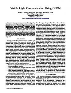
Table 1. Comparison of various modulation techniques for dimming support in VLC. The qualitative comparison among four different types of modulation techniques is presented for several properties. Three markers, ○, , and ×, represent three qualitative levels of the listed features: good, moderate, and bad, respectively. “Noiseless channel” represents the relative effectiveness of signal shaping under noiseless transmission. “Noisy channel” represents the relative effectiveness of signal shaping under a noisy channel. “Extreme dimming” indicates the performance when dimming targets are extreme (i.e., close to zero or one). “Complexity” indicates the complexity of implementation. “Channel/line coding” is related to the compatibility with error-correcting or run-length limited coding. “Color temperature shift” indicates the vulnerability of an LED emission color change.
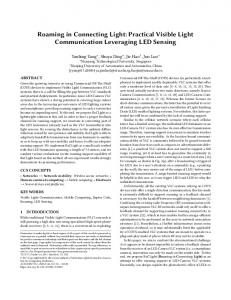
The message signals are assumed to span in CMdimensional space. The overall intensity is given by the sum of individual optical intensities and should satisfy the dimming target. Therefore, the dimming target imposes a constraint on the total intensity, which gives rise to a linear constraint on message symbols mapped in the CM-dimensional space. This offers a framework to facilitate the mathematical handling of multidimensional techniques. In order to fully exploit the degree of freedom, just as many PDs are needed to realize multiple-input multipleoutput (MIMO) technology, which allows the corresponding number of independent links. In a multicolored LED configuration, the color and intensity are chosen externally by the user, and their joint consideration leads to multiple color requirements. In an RGB arrangement, a message symbol can be mapped to one point in a three-dimensional color space defined by RGB intensities. Human perception of a color is easily described in this space. Since a color depends on relative RGB intensities, the normalization by intensity reduces the three-dimensional space into the two-dimensional CIE xyY chart [4]. Color shift keying (CSK) [4] is the first multicolor technique that modulates three component intensities for message transmission. Message symbols are associated with distinct colors such that the average color matches the user’s desire. Figure 3 gives an example of CSK within the gamut of colors, the set of colors represented using RGB sources, in the chart. The color gamut is given by a triangle with vertices corresponding to three sources. Given the target intensity and color, symbols are mapped on the chart such that the average color is equal to the target color. However, the constant intensity forces the use of only a two-dimensional region instead of the entire three-dimensional space. Furthermore, PDs normally have different responsivity patterns from human perception. This property introduces a new three-dimensional space, referred to as a signal space, which
140
describes message symbols detected by PDs. Since the detection performance depends on distances among symbols in the signal space rather than the color space, the data rate and color use can be enhanced by handling messages in the signal space. For this purpose, color-intensity modulation (CIM) [17] has been proposed that enables the modulation of both intensity and color. Since CIM uses the entire three-dimensional region to optimize symbol mapping in the signal space and adjust color requirements in the color space simultaneously, it outperforms CSK. In a configuration of LEDs located in different positions [18], the line-of-sight component is dominant in the VLC signal, which does not provide sufficient scattering for PD to distinguish multiple inputs. This hinders applying spatial multiplexing techniques in VLC. For performance enhancement, the beam width and field of view can be reduced at the cost of lowering the illumination range.
CODING FOR DIMMABLE VLC Compared to the technical progress made in the development of modulation techniques, the design of efficient forward error correction (FEC) schemes with dimming support has rarely been addressed. In the IEEE 802.15.7 standard, Reed-Solomon (RS) codes and their concatenations with convolutional codes are adopted as FEC. At transmitter, FEC encoding is followed by run-length-limited (RLL) line encoding, which is implemented using Manchester, 4B6B, and 8B10B codes, to provide DC balance and flicker mitigation. Thus, the RLL codewords — characterized by a small number of identical symbols — are encoded after the FEC based on RS codes. To increase the data rate, the source coding aspect of the code design can be emphasized instead of the RLL line coding. This indicates that a codebook containing as many codewords as possible is constructed for a given codeword
IEEE Communications Magazine • February 2015
KWON_LAYOUT.qxp_Author Layout 1/30/15 1:54 PM Page 141
IEEE Communications Magazine • February 2015
0.9 520 0.8
540
LED2 0.7
560 0.6 500 580
0.5
Symbol2
y
length. For this target, multiple-PPM (MPPM) has been proposed to construct a codebook of the theoretically best achievable rate [9]. However, MPPM lacks fast encoding/decoding rules that exponentially map many messages, and their implementation is impractical. On the other hand, the ISC [10] can be realized using inverse mapping of lossless compression for OOK/PAM signals. This is implemented using a reversal of practical Huffman encoding/decoding rules listed in Tables 2 and 3. Since the Huffman code allows optimal lossless compression, the resulting dimming adaptation approach is optimal with respect to the source coding gain. Therefore, the ISC establishes the maximally achievable data rate for a specific dimming target. The line coding and ISC may have weak error correction capability. Since the encoded symbols are fed directly into the optical modulator, the decoded symbols at the receiver are vulnerable to error propagation. Therefore, the unrecovered symbols are marked as erasures for the RS decoder. This limits the length of the line code such that the number of erasures does not go beyond a correctable range, although this reduces the potential to obtain additional coding gain from the use of longer line coding. The OOK mode, instead of a specific dimming support technique, uses inter-pulse padding where Manchester line coding maintains the duty cycle of the signal to exactly 50 percent, and the compensation symbols are inserted into the data frame. However, this limits the data rate. In addition, FEC encoding followed by line coding results in the adherence of the receiver to harddecision decoding, which incurs incompatibility with advanced iterative coding schemes [4]. To design an efficient FEC scheme that achieves arbitrary dimming targets in noisy environments, special consideration is needed for codeword symbol patterns. In principle, collection of binary sequences with non-uniform probability equal to the dimming target generates a codebook that achieves the dimming target. To offer error correcting capability, only a subset of codewords is chosen such that its elements are separated sufficiently from each other in Hamming distance. For practical considerations, encoding/decoding rules need to have useful properties, such as linearity, although the codebook exactly satisfying an arbitrary dimming target is inherently nonlinear. The codebook generated from a linear codebook such that all codewords have constant Hamming weight may be a useful choice for dimming support. This approach is applied to Reed-Muller (RM) codes to obtain a codebook that supports only 100/2b percent (b = 0, 1, …) dimming targets [19]. For an arbitrary dimming target, this is combined with compensation symbol insertion. However, this supports a limited range of data rates because the resulting data rate scales with O((log N)/N). On the other hand, a constant-weight codebook that chooses only the codewords of a Hamming weight equal to the dimming target through special algebraic theory can be used for the same objective. The existence of such a constant-weight codebook with an arbitrary weight is not well understood, and the range of available code rates is limited. In addition, very little
0.4
600 LED1 620 Target color
0.3 490
700
Symbol1 0.2 Symbol3 480
LED3
0.1 470 0.0 0.0
460 0.1
380 0.2
0.3
0.4
0.5
0.6
0.7
0.8
x
Figure 3. Example of a symbol constellation of CSK in CIE xyY color space (after [17]).
is known about encoding/decoding rules for constant-weight codes with manageable complexity. Compared to the range of achievable rates for dimmable VLC channels, the range of data rates where practically realized error correction schemes show good performance is very limited. A codebook with the exact-constant-weight property has a sub-exponential number of codewords, and the resulting code rate is strictly less than the achievable data rate. Therefore, such a constant-weight codebook is not an efficient choice for high data rate support. To extend the code rate significantly, the relaxation of the constant-weight constraint can be considered. In fact, this is the correct approach because the dimming requirement is imposed on the average value of the intensity instead of the instantaneous value. Scrambling of a linear codeword with a random sequence (i.e., masking a binary codeword with the sequence of the same length) can yield an average dimming equal to 50 percent. The weight of a codeword can be viewed as a binomial random variable, and the weight divided by the codeword length corresponds to the dimming value. Thus, the dimming value itself is a random variable with mean equal to the dimming target and variance inversely proportional to the codeword length. The adaptation of the arbitrary dimming target can be achieved by puncturing. Turbo codes are applied to obtain a large degree of data rate improvement [13, 20]. However, puncturing brings limited enhancement of the data rate, especially in a
141
KWON_LAYOUT.qxp_Author Layout 1/30/15 1:54 PM Page 142
Symbol/length
Probability
Codeword/length
0/1
0.3
00/2
10/2
0.21
01/2
11/2
0.49
1/1
Table 2. Example of Huffman encoding. This table is originally determined for lossless compression of the binary signals with non-uniform probabilities. However, this can be used in the demodulation of the optical signal at the receiver for VLC by mapping the detected symbols to the original message symbols in a sequential manner. The ISC employs reverse mapping of a lossless compression process where a certain non-uniform proportion of ones and zeros in the input signal are transformed to be as uniform as possible. This can be implemented by either table lookup or tree search. For example, a dimming target of 70 percent is given. A binary sequence with 70 percent ones and 30 percent zeros can be shortened losslessly via Huffman encoding. The resulting compression ratio is close to binary entropy H(0.7), which is equal to the maximally allowed rate for a dimming target of 70 percent.
Symbol/length
Probability
Codeword/length
00/2
0.25
0/1
01/2
0.25
10/2
1/1
0.5
11/2
Table 3. Example of inverse Huffman encoding. This table is obtained by inversely mapping the input and output of Table 2. This table maps a series of message symbols normally with uniform probability of ones and zeros to a series of symbols in which the time average meets the dimming requirement. The inverse Huffman coding is carried out using the table that corresponds to the inverse mapping of Table 2. Since the decompression ratio is equal to the reciprocal of the entropy associated with the target dimming, the resulting dimming of an ISC-encoded signal comes close to the target dimming. The ISC symbols are decoded straightforwardly using the compression table of Table 2. Note that although the dimming target of 70 percent is not precisely met, it can be achieved for sufficiently long codewords.
low dimming regime. Therefore, additional techniques are expected for an extension of the range of available data rates.
TECHNICAL CHALLENGES FOR ENHANCED VLC SYSTEMS This section overviews the key technical challenges faced by VLC PHY systems: •Design of capacity-approaching coding techniques: The error correction performance of the latest coding techniques developed for dimmable VLC is far from the capacity in the low/high dimming regime. Almost all practical FEC techniques employ time-domain dimming approaches, such as intra-pulse insertion and inter-pulse padding, which degrade the data rate severely. To be precise, the data rate achieved by insertion/padding schemes has a linear relationship with the dimming target, while the capacity is given by the binary entropy of the dimming target. Therefore, the difference
142
between the capacity and practically achieved data rate becomes larger as the dimming target deviates from 50 percent. This suggests that existing practical schemes do not fully exploit a potentially favorable property leading to datarate enhancement. For example, the use of variable padding symbol positions can lead to an increase in data rate. •Consideration of the LED physical characteristics: The LED is subject to chromaticity (color) shift and nonlinearity caused by the change of driving current and operating temperature by Joule heating. This change in intensity causes a slight change in light color and brightness. This poses a critical challenge for achieving multi-level transmissions implemented with LEDs. The impact is more serious in RGB LEDs than PC white LED. Furthermore, proper control technologies for color mixing are needed under changes to various parameters (e.g., temperature, driving current, aging). A nonlinear input/output relationship of an LED is an unavoidable issue that requires fine intensity control of LED emission. •Flicker regulations: Worldwide legislative changes to regulation of flicker in LED lighting applications are ongoing. In Japan, there is a regulation for brightness change in LEDs within the range 100–500 Hz, provided by Product Safety Electrical Certification. In North America, the progress in defining flicker is made toward minimizing the relative amount of changes in light intensity by introducing some metrics for flicker measurements, such as percentage flicker and flicker index, suggested by the Illuminating Engineering Society. According to these metrics, the shape of the optical pulse can also have an impact on the flicker effect. Therefore, intensive cross-disciplinary research on flicker from physiology and engineering perspectives is required.
CONCLUSION This article reviews major technical design considerations for VLC systems operating with LEDs and PD detectors. High-rate transmission over a broad visible light spectrum and dimming support are identified as the two main driving forces that motivate the creation of new enhanced specifications in VLC. To create technically sound enhancement, the system should satisfy regulatory requirements and optimize system performance. Modifications in coding and modulation are necessary to support adaptive dimming, whereas new coding schemes are essential for performance enhancement. From this perspective, the system design considerations highlighted in this article are intended to serve as guidelines to fulfill these requirements and to motivate further research in design of transmission techniques compatible with dimming support.
ACKNOWLEDGMENT This research was supported by the Basic Science Research Program through the National Research Foundation of Korea (NRF) funded by the Ministry of Science, ICT & Future Planning (NRF-2014R1A1A1006082).
IEEE Communications Magazine • February 2015
KWON_LAYOUT.qxp_Author Layout 1/30/15 1:54 PM Page 143
REFERENCES [1] T. Komine and M. Nakagawa, “Fundamental Analysis for Visible-Light Communication System Using LED Lights,” IEEE Trans. Consumer Electronics, vol. 50, no. 1, Feb. 2004, pp. 100–07. [2] H. Elgala, R. Mesleh, and H. Haas, “Indoor Optical Wireless Communication: Potential and State-of-the-Art,” IEEE Commun. Mag., vol. 49, no. 9, Sept. 2011, pp. 56–62. [3] K. Lee, H. Park, and J. R. Barry, “Indoor Channel Characteristics for Visible Light Communications,” IEEE Commun. Lett., vol. 15, no. 2, Feb. 2011, pp. 217–19. [4] S. Rajagopal, R. D. Roberts, and S.-K. Lim, “IEEE 802.15.7 Visible Light Communication: Modulation Schemes and Dimming Support,” IEEE Commun. Mag., vol. 50, no. 3, Mar. 2012, pp. 72–82. [5] S. M. Moser, “Capacity Results of an Optical Intensity Channel with Input-Dependent Gaussian Noise,” IEEE Trans. Info. Theory, vol. 58, no. 1, Jan. 2012, pp. 207–23. [6] S. Hranilovic and F. R. Kschischang, “Optical IntensityModulated Direct Detection Channels: Signal Space and Lattice Codes,” IEEE Trans. Info. Theory, vol. 49, no. 6, June 2003, pp. 1385–99. [7] J. G. Smith, “The Information Capacity of Amplitudeand Variance-Constrained Scalar Gaussian Channels,” Info. and Control, vol. 18, 1971, pp. 203–19. [8] G. Ntogari et al., “Combining Illumination Dimming Based on Pulse-Width Modulation with Visible-Light Communications Based on Discrete Multitone,” J. Opt. Commun. Net., vol. 3, no. 1, Jan. 2011, pp. 56–65. [9] K. Lee and H. Park, “Modulations for Visible Light Communications with Dimming Control,” IEEE Photonics Tech. Lett., vol. 23, no. 16, Aug. 15, 2011, pp. 1136–38. [10] J. K. Kwon, “Inverse Source Coding for Dimming in Visible Light Communications Using NRZ-OOK on Reliable Links,” IEEE Photonics Tech. Lett., vol. 22, no. 19, Oct. 1, 2010, pp. 1455–57. [11] S. Shamai, “Capacity of a Pulse Amplitude Modulated Direct Detection Photon Channel,” IEE Proc., vol. 137, no. 6, Dec. 1990, pp. 424–30. [12] T. H. Chan, S. Hranilovic, and F. R. Kschischang, “CapacityAchieving Probability Measure for Conditionally Gaussian Channels with Bounded Inputs,” IEEE Trans. Info. Theory, vol. 51, no. 6, June 2005, pp. 2073–88. [13] S. H. Lee, K.-I. Ahn, and J. K. Kwon, “Multilevel Transmission in Dimmable Visible Light Communication Systems,” J. Lightw. Tech., vol. 31, no. 20, Oct. 15, 2013, pp. 3267–76. [14] T. Ohtsuki, “Multiple-Subcarrier Modulation in Optical Wireless Communications,” IEEE Commun. Mag., vol. 41, no. 3, Mar. 2003, pp. 74–79. [15] J. Armstrong and A. J. Lowery, “Power Efficient Optical OFDM,” Electronics Lett., vol. 42, no. 6, Mar. 16, 2006, pp. 370–72.
IEEE Communications Magazine • February 2015
[16] W. O. Popoola and Z. Ghassemlooy, “BPSK Subcarrier Intensity Modulated Free-Space Optical Communications in Atmospheric Turbulence,” J. Lightwave Tech., vol. 27, no. 8, Apr. 15, 2009, pp. 967–73. [17] K.-I. Ahn and J. K Kwon, “Color Intensity Modulation for Multicolored Visible Light Communications,” IEEE Photonics Tech. Lett., vol. 24, no. 24, Dec. 15, 2012, pp. 2254–57. [18] L. B. Zeng et al., “High Data Rate Multiple Imput Multiple Output (MIMO) optical Wireless Communications Using White LED Lighting,” IEEE JSAC, vol. 27, no. 9, Dec. 2009, pp. 1654–62. [19] S. Kim and S.-Y. Jung, “Novel FEC Coding Scheme for Dimmable Visible Light Communication Based on the Modified Reed-Muller Codes,” IEEE Photonics Tech. Lett., vol. 23, no. 20, Oct. 15, 2011, pp. 1514–16. [20] S. H. Lee and J. K. Kwon, “Turbo Code-Based Error Correction Scheme for Dimmable Visible Light Communication Systems,” IEEE Photonics Tech. Lett., vol. 24, no. 17, Sept. 1, 2012, pp. 1463–65.
BIOGRAPHIES SANG H YUN L EE [M] (
[email protected]) received his B.S. and M.S. degrees from Korea Advanced Institute of Science and Technology (KAIST) in 1999 and 2001, respectively, and his Ph.D. degree from the University of Texas at Austin in 2011. Since 2014, he has been with the Department of Information and Communications Engineering, Sejong University, Seoul, Korea. His research interests include coding/modulation technology, optimization and their applications to optical wireless communication, communication networks, and bio/material science. S UNG -Y OON J UNG [M] (
[email protected]) received his B.S. degree from Korea University in 2000 and the M.S. and Ph.D. degrees from KAIST in 2002 and 2006, respectively. He was with Samsung Electronics from 2006 to 2009. Since 2009, he has been with the Department of Electronic Engineering, Yeungnam University. His research interest is communication signal processing and its application to optical wireless communication, UWB communications, and nanonetworks. J A E K Y U N K W O N [SM] (corresponding author) (
[email protected]) received his B.S., M.S., and Ph.D. degrees from KAIST in 1996, 1998, and 2003, respectively. Since 2006, he has been with the Department of Electronic Engineering, Yeungnam University, Gyeongsan, Korea. His research interests include visible light communications, wireless location, and underwater communications.
143