Jun 6, 2010 - Motor using Advanced Signal and Data Processing Tools. S. Das, P. Purkait ... Traditional methods of online monitoring and insulation.
IEEE Transactions on Dielectrics and Electrical Insulation
Vol. 18, No. 5; October 2011
1599
Monitoring of Inter-turn Insulation Failure in Induction Motor using Advanced Signal and Data Processing Tools S. Das, P. Purkait Haldia Institute of Technology Department of Electrical Engineering Haldia, WB 721657, India and D. Dey and S. Chakravorti Jadavpur University Department of Electrical Engineering Kolkata, WB 700032, India
ABSTRACT Detection of stator winding inter-turn insulation failure at early stages is crucial for promoting safe and economical use of induction motors in industrial applications. Whereas major insulation failures involving larger percentages of winding are easily discernible from magnitude of supply current, minor inter-turn insulation failures involving less than 5% of turns often go undetected. The present contribution reports experimental results of minor faults due to inter-turn insulation failures in stator windings of induction motor under different loading conditions being analyzed using data and signal processing tools combining Park’s Transform and Cross Wavelet Transform. Rough Set Theory (RST) based classifier has been used for fault severity monitoring. Index Terms — Induction motor, inter-turn insulation failure, Park’s transformation, cross wavelet transform, rough set theory.
1 INTRODUCTION INDUCTION motors have become the main workhorse of industrial installations mainly due to their ruggedness, reasonably small size, low cost, low maintenance, easy availability, and ability to work under harsh working environments. In spite of their relatively high accuracy, induction motors when subjected to undesirable stresses during their service conditions may develop internal faults [1]. Faults in stator winding have been found to be more prevalent and potentially destructive leading to motor failures. Studies over the years have shown that probability of induction motor failures arising from stator winding insulation breakdown can be as high as 30% – 40% [1-2]. In most cases, stator inter-turn insulation faults start as minor and often go undetected, that finally may grow and lead to major ones [3]. Initiating primarily from insulation degradation through contamination or abnormal electrical, thermal, mechanical, and environmental stresses [4], such localized turn-to-turn faults often produce hotspots, causing rapid degradation that may finally lead to a catastrophic failure such as severe turnto-ground failure of the major insulation. Such situations are more frequently encountered in VFD (variable frequency drive) systems where induction motors are fed by PWM Manuscript received on 6 June 2010, in final form 21 January 2011.
inverters. Winding insulation of such an induction motor is strongly stressed by the PWM voltage waveform. Impedance mismatch between the feeding cable and the winding can cause over voltages at the motor terminals. In addition, voltage distribution across the stator winding can become non-uniform and first few turns of phase windings experience severe voltage stress. Partial discharge (PD) or dielectric breakdown between turns are the possible consequences of such severe voltage stresses. In inverter fed induction motors, thus, failures generally begin by inter-turns breakdown [5-6]. In this era of competitive market and deregulation, it has become more pertinent that scheduled maintenance and routine monitoring give way to condition based maintenance and efficient fault diagnosis. Early indication of insulation failure within the stator winding would not only ensure speedy repair, but also would enable better scheduling of future maintenance and repair strategies [7-8]. Commercially available off-line and in-service tests for assessing the condition of rotor and stator winding are reviewed in [9]. Off-line tests include insulation resistance (IR) measurement, polarization index (PI) measurement, dc and ac Hipot test, dc conductivity test, capacitive impedance tests, dissipation (or power) factor test, surge comparison test etc. Traditional methods of online monitoring and insulation fault diagnosis were based upon methods such as indirect measurement of the turn-to turn capacitance [10], online Partial Discharge (PD) analysis [9, 11], axially transmitted
1070-9878/11/$25.00 © 2011 IEEE
1600
S. Das et al.: Monitoring of Inter-turn Insulation Failure in Induction Motor using Advanced Signal and Data Processing Tools
leakage flux sensing, stator current and voltage harmonic analyses, recording the negative-sequence impedance [12], thermal monitoring, end-winding vibration monitoring, current signature analysis [9] etc. Subsequent studies however, pointed out that many of the traditional methods are too sensitive to supply voltage distortions [4], inherent machine asymmetries [13], overlapping effects of stator and rotor faults, etc that often led to misdirection and anomalies in fault diagnosis results. A survey of the state of art in the use of stator currents for induction motor rotor faults diagnosis has been detailed in [14]. Recent progresses in the area of stator insulation fault diagnosis have involved artificial intelligence (Al) based techniques such as expert system (ES), fuzzy logic, artificial neural network (ANN) [15], Motor Current Signature Analysis (MCSA) [16], and combined methodology, such as Neural-Fuzzy systems [17]. These techniques have been demonstrated to have substantial advantages over conventional fault diagnostic approaches. Many of these modern stator insulation fault diagnosis techniques, however, come with the associated cost of intricate and expensive sensors assemblies [18]. Challenges still remain, thus, in the use of effective, accurate yet economically prudent techniques that can integrate readily available monitoring devices with modern efficient signal and data processing tools for reliable diagnosis of minor insulation faults in induction motors. The present contribution thus attempts to address these critical issues through several careful steps involving modern techniques of fault signal acquisition, data reduction, signal processing, feature extraction, and data processing. In the present study, experimental investigations have been performed with artificially created faults in stator winding insulation of an induction motor under different loading conditions. Effects of abnormal operating conditions, such as supply voltage unbalance (voltage sag and voltage swell) have also been studied. Line current signals recorded from motor terminals are processed through Park’s transformation corresponding to different fault conditions. Subsequent to suitable data reduction stage, Cross Wavelet Transform (XWT) has been used on the fault signals to extract meaningful and effective features. To classify the extracted features, a classification technique based on Rough set theory (RST) has been used. It is pertinent to mention here that the objective of this work is not to highlight performance of the classifier, but to establish a scheme to detect minor insulation faults in stator winding unambiguously with reasonable degree of accuracy.
A data acquisition system with YOKOGAWA 3-phase power meter [Model WT 230] to capture stator current signals under different experimental conditions. A customized stator winding where all stator coil ends and several tappings from a number coils of the motor were brought out of the machine to a patch-board. This arrangement allowed several fault conditions to be created by means of appropriate short-circuiting links simulating inter-turn insulation failures. A dc generator has been coupled with the induction motor. A group of lamps are connected to the dc generator output with provision of loading the generator with different combinations. Varying the generator load thus in turn mechanically loads the induction motor to different levels. Schematic arrangements and experimental setup of the proposed scheme are shown in Figure 1 and Figure 2 respectively. The induction motor has been tested under two different conditions as stated below: A) Rated three phase balanced supply from 3-phase variable auto-transformer is fed to the motor under healthy as well as under inter-turn insulation failure conditions of the stator phase windings at no-load and at four other loads (20%,40%, 60% and 80%) of the motor. B) Healthy motor is fed from three phase balanced supply through voltage sag-swell introducing circuit, placed inbetween 3-phase variable auto-transformer and the motor.
Figure 1. Schematic diagram of test circuit.
2 EXPERIMENTAL DETAILS In the present work, experimental studies have been performed on a 0.5 HP, 415V, 4 pole, 3-phase induction motor. To carry out the desired experiment, the following apparatus and arrangements have been used: A 3-phase auto-transformer which has the capability to provide variable voltage ranging from 0% to 125% of the primary side rated supply voltage. A voltage sag-swell introducing circuit which has been designed using major components such as TRIACs, IC555 timers, opto-coupler and rheostat, to introduce either voltage sag or voltage swell in one phase at a time.
Figure 2. Photograph of test set-up.
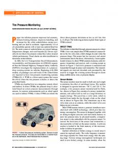
2.1 EXPERIMENT UNDER CONDITION A Star connected stator winding of the three phase induction motor under test has 8 coils and 560 turns per phase with enamel insulation between turns. One of the three phase windings (Y-phase in the present study) is customized to implement as many as eighteen fault conditions due to interturn insulation failures with the help of winding structure as shown in Figure 3.
IEEE Transactions on Dielectrics and Electrical Insulation
Vol. 18, No. 5; October 2011
1601
been performed with motors exclusively driven by a sinusoidal source. Thus, unlike in PWM fed induction motors, effect of high frequency components is not expected in current signature. Above mentioned experimental procedure was repeated for other four different loading conditions of the motor. DC generator coupled with the motor and lamp load connected with generator output terminals were used to load the motor at 20%, 40%, 60% and 80% load levels. During the course of experiments, it was felt that the risk of damaging the stator winding is always very high while motor is operated at higher load with inter turn faults involving relatively larger number of turns. So, experiments involving inter-turn insulation failures with motor under loaded conditions were performed these quickly without allowing much temperature rise.
Figure 3. Internal tap positions in Y-phase winding
Short circuiting any two of the taps externally emulates insulation failure between turns thereby creating short circuit fault in the stator phase winding. Such a fault changes the otherwise symmetrical stator current to one that is asymmetrical. Since, the objective of this work is to identify minor faults due to stator inter-turn insulation failures, the tests are carried out at rated voltage after shorting a small number of stator turns to avoid damage in the winding due to flow of excessive current in the short-circuited coils. To verify sensitivity of the proposed scheme, it is tested to identify fault cases which are artificially created involving even less than 0.2% (1 turn) to 3.75% (21 turns) turns of phase winding as described in Table 1. It is because, proposed scheme needs to exhibit enough sensitivity to meet the main objective of this work, which is to accurately identify the minor inter-turn insulation failures involving less than 5% turns of phase winding. Figure 1 shows the schematic diagram of the test circuit and this part of the experiment is carried out by-passing the voltage sag-swell introducing block. Tests are performed under different degrees of insulation fault conditions as listed in Table 1. In Table 1, no-fault state depicts the healthy condition of the motor insulation. At first, motor was subjected to operate at no load and measurements corresponding to three phase stator line current signals for 25 cycles were captured through three phase power meter and PC arrangement for further analysis. Since noise can always mask the fault signatures, and the same experiment was repeated for several times in order to reach reliable conclusions. Therefore, for each fault condition, in fact, seven data sets were recorded at different points of time for analysis. Moreover, during analysis, data for average of 25 cycles have been used to further reduce the effects of noise components. Effect of high frequency noise components in stator supply current is more prominent in PWM inverter fed inverter duty induction motors. Classical Fast Fourier Transform (FFT) [16, 19] as signal processing had been suggested to detect filter out high frequency undesirable components from the current signatures. In the present study, however, experiments have
2.2 EXPERIMENT UNDER CONDITION B The second part of the study is made by implementing an arrangement to introduce supply condition disturbances such as voltage unbalance (voltage sag and swell) which may be caused due to some abnormalities occurring ahead of the feeding point of motor. In this experiment momentary voltage sag and swell situations are characterized as motor external fault conditions, following the IEEE standard1159. With the help of a voltage sag-swell introducing circuit, voltage unbalance conditions to the motor are introduced to
Sl. No.
1 2 3 4 5 6 7 8 9 10 11 12 13 14 15 16 17 18
Table 1. Motor insulation fault conditions. % of stator No. of Insulation winding Shorting turns fault type turns per between taps involved phase shorted No short 0 0 No fault Y25-Y26 1 0.18 T1 Y11-Y12 2 0.36 T2 Y21-Y22 3 0.53 T3 Y12-Y13 4 0.71 T4 Y22-Y23 5 0.89 T5 Y13-Y14 6 1.07 T6 Y23-Y24 7 1.25 T7 Y31-Y32 8 1.43 T8 Y42-Y41 9 1.61 T9 Y2-Y11 10 1.78 T10 Y32-Y33 11 1.96 T11 Y43-Y42 12 2.14 T12 Y33-Y34 13 2.32 T13 Y44-Y43 14 2.5 T14 Y26-Y27 16 2.85 T16 Y26-Y28 18 3.21 T18 Y25-Y28 19 3.39 T19 Y25-Y29 21 3.75 T21
the same phase on which the internal faults, i.e. inter-turn insulation failures has been carried out. During the events of such abnormal operating condition, the motor is operated without any internal fault being created. The static switch and rheostat are so arranged that the duty cycle of the TRIAC, controlled from the IC555 timer and opto-coupler (MOC 3021) circuit, effectively sets the duration of under voltage (voltage sag) or over voltage (voltage swell) with the 3-phase auto-transformer adjusted to supply the motor rated voltage. As a result, one stator phase receives under voltage or over
1602
S. Das et al.: Monitoring of Inter-turn Insulation Failure in Induction Motor using Advanced Signal and Data Processing Tools
voltage, whereas other two phases continue to receive normal rated voltages from auto-transformer. Stator line current signals have been captured through power meter and PC arrangement for further analysis.
3 SIGNAL PROCESSING AND DATA REDUCTION 3.1 PARK’S VECTOR APPROACH In three-phase induction motors, the mains supply normally does not have neutral wire. Therefore, the line current fed to the motor has no homo-polar component. A suitable twodimensional (2-D) representation can then be used to describe three-phase induction motor performance. A commonly used 2-D representation is based on the Park’s transformation which has been successfully applied in the steady-state diagnosis of rotor faults, stator turn-to-turn insulation faults, unbalanced supply voltage conditions, and mechanical loadmisalignments [20]. The Park’s vector components (Id,Iq) are a function of mains three phase variables (Ia, Ib, Ic ) as 2 Ia 3 1 Iq Ib 2 Id
1 6 1 2
Ib
1 6
Ic
the one causing 19 turns shorted in Y phase winding (Figure 4). The first step of data reduction, without losing valuable fault information, is to convert the three phase line current in to a two-phase equivalent current (2-D) using the Park’s transformation described by equations (1) and (2). Figure 6a shows the nature of deviations of Park’s vector components under 19 shorted turns in Y phase winding from that of healthy motor and Figure 6b shows a case of supply voltage unbalance, such as 10% under voltage (sag) in the motor supply, with the motor remaining internally healthy.
(1)
Ic
(a)
In ideal conditions, three-phase currents lead to a vector with the following components: 6 I M sin t 2 6 Iq I M sin t 2 2 Id
(2)
Where IM is the maximum value of supply phase current and ω is the supply frequency. The basis of diagnosis technique proposed in this article is in analyzing the Park’s vector components (Id,Iq) corresponding to the motor current signatures under different fault conditions. 3.2 DATA REDUCTION Stator inter-turn insulation failures and resulting shortcircuiting of turns lead to impedance unbalance among different phase windings. In the case of minor faults, however, these unbalances are hardly discernible from simple visual inspection of the three-phase line currents drawn by the motor. In addition to that, visual appearance of the three-phase line currents may not be suitable for reliable detection of internal minor insulation faults since these waveforms are very much susceptible to supply voltage distortions. Figure 4a shows the healthy motor line current signals under no-load and 60% load. Figure 4b shows the motor line current signals with 19 turns shorted in Y phase under no-load as well as 60% load. Figure 5 shows motor line current signals corresponding to 10% under voltage in Y-phase supply. It can be observed that though supply voltage unbalance, such as 10% under voltage in Y phase can be recognized (Figure 5), it is visually difficult to detect any appreciable variation in the 3-phase supply current profile in the case of internal insulation fault, such as
(b) Figure 4. Three-phase line currents for motor with (a) healthy winding and (b) 19 turns shorted in Y phase winding. Suffix NL – for no load; L – for 60% of full load.
Figure 5. Three-phase line currents for motor with 10% under voltage in Y phase.
IEEE Transactions on Dielectrics and Electrical Insulation
Vol. 18, No. 5; October 2011
(a)
these which can be used to quantitatively characterize faults at different loading conditions. The deviation in Park’s vector components (Id, Iq) under fault condition from that under healthy motor condition encouraged the use of Cross-wavelet transform to be used in this work. The Cross-wavelet transform, which is essentially an extension of wavelet analysis, measures the degree of correlation between two waveforms in time-frequency domain. In reality, crosswavelet spectrum can find the regions in time-frequency plane where the two waveforms under comparison possess high common power, and also the regions where they correlate poorly. Successful uses of cross wavelet transform for impulse fault classification of transformers, and classification of noisy partial discharge (PD) pulses have been reported in [21-22]. Cross-wavelet spectrum analyses have also been reported by other researchers in geosciences [23], biomedical signal processing [24] and transient analysis [24]. While a detailed mathematical background can be found in [23], an overview of cross-wavelet transform is given below for ready reference. If x(t) and y(t) are two time domain signals, the crosswavelet transform is defined as: 1 x y * a b dadb (3) W xy ( s, ) W (a, b)W ( , ) 2 c
It is interesting to note from Figure 6 the fact that Park’s vector components corresponding to internal as well as supply voltage unbalance have subtle, yet definite deviations in shape and nature from their healthy condition counterparts. On close inspection of Figure 6, it may be further observed that, Id is increased in both cases but Iq becomes higher in the case of ‘turns short’ and lower in the case of ‘sag’ with respect to the healthy counterparts. Similar observations may be made for other internal fault and voltage unbalance cases. This trend in deviation of Id and Iq may give preliminary indication of the difference between the natures of the defect (supply voltage unbalance or stator inter-turn faults). However, a closer examination seems necessary to classify internal faults involving different number of turns-short at various load levels along with instances of supply voltage unbalance. The proposed classifier is hence presented with an integrated data set involving both turns-short and supply voltage unbalance cases. Focus of this present study has, however, been restricted to detailed classification of minor internal insulation faults in stator winding at various load levels with supply voltage unbalance (sag or swell) being categorized under one single class, termed hereafter as VU (Voltage Unbalance).
s
s
a
Here, W ( s, ) and W ( s, ) are the wavelet transform of x(t) and y(t), respectively, with respect to a mother wavelet ψ(t). ‘s’ and ‘τ’ are usual ‘dilation’ and ‘translation’ c parameters. is a constant, having value, y
x
(b) Figure 6. Comparative profiles of Park’s vector components for (a) healthy with 19 turns shorted in Y phase winding, and (b) healthy with 10% under voltage in Y phase.
1603
c
( )
2
d
The waveforms of Park’s vector components (Id, Iq) obtained for different fault conditions and for the healthy state are used to get cross-wavelet spectra. Figure 7 shows an example plot of such Cross-wavelet transform between Id, at healthy condition, and Id with 10 turns insulation failure in Y phase. As the Id and Iq are time domain signals, ‘τ’ represents translation along time axis or can also be considered as translation along data samples.
4 FAULT FEATURE EXTRACTION USING CROSS WAVELET TRANSFORM Once the Park’s vector components as discussed in the previous section are obtained, it is now of importance to device suitable technique to extract meaningful features out of
Figure 7. Enlarged view of cross wavelet spectrum obtained by performing cross wavelet transform between Id components of healthy winding and 10 turns insulation failure in Y phase winding at no-load.
1604
S. Das et al.: Monitoring of Inter-turn Insulation Failure in Induction Motor using Advanced Signal and Data Processing Tools
In the present study, Morlet mother wavelet is considered. This choice of mother wavelet is purely dependent on the nature of the problem. In this case it has been found that the performance of the scheme using Morlet wavelet is better than other commonly used mother wavelets. However, depending on the problem some other mother wavelet may be chosen. The Cross-wavelet spectrum is plotted using the magnitude of W
xy
and the phase angle, tan 1
{W } . {W xy } xy
and ( s, ) depending upon or any other features from the nature of the problem. In the present case, the abovementioned eight features are found to be sufficient for; using which identification of the faults can be done at different loading conditions of the motor with reasonable accuracy. W xy
F1
parts of W respectively. In Figure 7, W xy values at different ‘data samples’ versus ‘scale’ are plotted. The y-axis marks the ‘scale’, which can be considered as inverse of frequency. Color of the figure at a particular point shows the magnitude of W xy at that location in time-frequency plane. The color-bar given on right side of Figure 7 indicates the strength corresponding to a color. Higher the strength of W xy , higher is the degree of correlation between the two waves, i.e. common power at that point on time-frequency plane is higher. Black arrows on the plot indicate the phase angle difference between the two waves under comparison. Arrows pointing towards right in Figure 7, indicate “inphase” (i.e. phase difference in zero) while arrows pointing left indicate “anti-phase” (i.e. phase difference is 1800) conditions between the two waves. In general, the angles made by the arrows with the x-axis indicate the respective phase angle differences between the two waves. The ‘U’ shaped and black colored line on the plot shows the “cone of influence” (COI) which essentially indicates the effective region for the analysis in the present work. Once the cross wavelet spectrum is obtained, extraction of feature there from is the most important aspect like in any classification or clustering problem. Choice of suitable features for a particular problem may be considered as a combination of trial-and-error and application of experience. For identification of fault patterns in the given problem, eight features have been extracted from each of the crosswavelet spectra, in a way similar to those followed in the cases of impulse fault identification and PD pattern classification [21-22] by the authors. The features (from F1 to F8) are listed in Table 2. Eight features (F1D to F8D) are obtained performing cross-wavelet between healthy Id and faulty Id current components of Park’s vector. Similarly, another eight features (F1Q to F8Q) are obtained from crosswavelet between healthy Iq and faulty Iq current components of Park’s vector. The reason behind choice of features F1-F8 is that they represent certain salient features of the cross-wavelet spectrum and gave reasonably acceptable classification performance in [21-22]. However, one may choose some other features such as, location of local peaks of
W xy
and ( s, ) surfaces, if any,
s s
xy xy Here, {W } and {W } indicate the real and imaginary
xy
Table 2. Features obtained from cross wavelet transform. Feature Expression Feature Expression F2 xy xy 2 2
W
W
W ( s , ) xy
W xy ( s, )
( s, )
s
F3
W
xy
( s, )
F4
s
s (s, ) (s, ) 2
2
peak
( F 3 W
xy
( s, ) ) 2
s
( s max s min )( max min ) F5
( s, )
s
( s max s min )( max min ) F6
( s, ) s
s
( s, ) peak
s
F7
(s, ) s
( s max s min )( max min )
F8
( F 7 ( s, ) )
2
s
( s max s min )( max min )
5 CLASSIFICATION OF EXTRACTED FEATURES To classify different fault conditions at varying loads of the motor using the extracted features, a classification technique based on Rough set theory (RST) has been used. It is evident that there is no prior knowledge regarding which features of the cross-wavelet spectrum will be more suitable and should be taken for classification of fault patterns. Number of features suitable for one application may vary from the other. So, the data table obtained after extraction of the features may be prone to imprecise or superfluous information. As Rough sets are well-suited for these kinds of problems [26-32], a classifier based on Rough set theory has been examined here. Theoretically speaking, any other classification technique apart from RST can also be used in this case for the same purpose. It is pertinent to mention here that main aim of this work is not to highlight performance of the classifier but rather stress on the results of fault creation, data reduction, signal processing, and fault feature extraction. Since the choice of classification methodology does not contribute to the novelty of the present scheme, details of the classifier algorithm has been intentionally limited to the very basics in this paper. A brief description of RST is given here to comprehend the classification technique. The next section describes the method of fault classification including identification of supply voltage unbalance at no-load condition of motor. Section next of that describes the effect of load on the accuracy of the same method to identify stator inter-turn insulation faults for four different load conditions of the motor.
IEEE Transactions on Dielectrics and Electrical Insulation
Vol. 18, No. 5; October 2011
5.1 CLASSIFICATION UNDER NO-LOAD CONDITION Fault features extracted from cross wavelet transform of Park’s vector components (Id, Iq) correspond to no load operation of the motor are used in this fault classification part. In RST, data is presented in a decision table (or data table) in which, each row represents an object (e.g. information regarding different fault cases in the stator winding) and each column represents an attribute. For example, in the present problem decision table contains extracted features (F1DF8D& F1Q-F8Q) as the 16 condition attributes and the fault type as the decision attribute. For decision attribute the following notation is followed in the present problem: D1= insulation failure involving 1-2 turns; D2= insulation failure involving 3-4 turns; D3 = insulation failure involving 5-6 turns and so on. Finally, D11 represents the case when greater than 20 turns are shorted due to insulation breakdown and D12 corresponds to voltage unbalance (like, sag or swell). Samples of normalized decision table are shown in Table 3A and 3B. Normalization has been done with respect to the maximum value of each individual feature. Relations between the
1605
decision attributes and fault types are more elaborately described in the normalized decision table shown in Table 3A and 3B. Out of the total seven sets of data recorded for each type of fault (T1, T2,…T21, VU), three to four sets for each fault type chosen randomly, have been used to form the normalized decision table. Remaining fault data sets have been reserved for testing the decision rules. In RST based classification algorithm, the data table is discretized. This indicates that each condition attribute value is divided into several meaningful ranges and in turn identical attributes or dispensable attributes are removed, if any. Methods for obtaining indispensable attributes from a complete set of condition attributes have been discussed in detail in [21-22, 32], and are hence omitted from the current report. It is found that out of the total sixteen attributes (features) F2D, F3D, F6D, F7D, F8D, F1Q, F2Q, F3Q, F4Q, F5Q and F6Q are dispensable and the remaining five attributes are indispensable.
Table 3A. Normalized Decision Table Obtained from Park’s Vector D-axis Components Condition Attributes F1D
F2D
F3D
F4D
F5D
F6D
F7D
F8D
Decision Attribute
Fault Type
1
0.61623
0.008496
0.03351
0.99568
0.97806
7.68E-05
7.54E-05
0.85384
D1
T1
2
0.61314
0.008529
0.03357
1
0.97658
7.64E-05
7.54E-05
0.86167
D1
T1
3
0.61293
0.008553
0.03333
0.99436
0.9773
7.62E-05
7.52E-05
0.85541
D1
T1
4
0.61411
0.0085
0.03337
0.99102
0.97666
7.66E-05
7.58E-05
0.85766
D1
T1
5
0.71178
7.67E-05
0.01669
0.93518
0.99985
7.62E-05
0.0168
0.9875
D1
T2
6
0.70936
7.68E-05
0.01673
0.93177
0.99342
7.64E-05
0.0168
0.98675
D1
T2
7
0.70687
7.68E-05
0.01672
0.93693
1
7.67E-05
0.01677
0.99262
D1
T2
. .
. .
. .
. .
. .
. .
. .
. .
. .
. .
. .
48
0.56567
0.62325
0.81231
0.61437
0.21844
0.61886
0.7795
0.61201
D7
T14
49
0.56753
0.62351
0.81539
0.61496
0.21751
0.622
0.78239
0.61573
D7
T14
. .
. .
. .
. .
. .
. .
. .
. .
. .
. .
. .
84
0.65234
0.62293
0.6539
0.50792
0.23772
0.58875
0.65652
0.53371
D12
VU
Table 3B. Normalized Decision Table Obtained from Park’s Vector Q-axis Components Condition Attributes Decision Attribute F2Q F3Q F4Q F5Q F6Q F7Q F8Q
Fault Type
Objects
Objects
F1Q
1
0.63036
0.04101
0.06467
0.9958
0.97835
2
0.62739
0.04105
3
0.62719
0.04107
4
0.62832
5
0.7224
6 7 . . 75 76 . . 84
0.03285
0.03237
0.85843
D1
T1
0.06473
1
0.9769
0.03285
0.03237
0.86598
D1
T1
0.06449
0.99452
1
0.03285
0.03237
0.85992
D1
T1
0.04102
0.06453
0.99129
0.97697
0.03285
0.03237
0.86213
D1
T1
0.03287
0.04839
0.93715
0.99982
0.03285
0.04856
0.98787
D1
T2
0.72007
0.03287
0.04842
0.93385
0.9935
0.03285
0.04856
0.98717
D1
T2
0.71768 . . 0.54283
0.03287 . . 0.45254
0.04841 . . 0.63043
0.9388 . . 0.53396
0.97762 . . 0.2161
0.03285 . . 0.42729
0.04853 . . 0.6017
0.99283 . . 0.52169
D1 . . D11
T2 . . T21
0.54463 . . 0.66514
0.45164 . . 0.6353
0.6317 . . 0.66507
0.53634 . . 0.5227
0.21434 . . 0.24879
0.42931 . . 0.60224
0.60208 . . 0.6676
0.52309 . . 0.54838
D11 . . D12
T21 . . VU
1606
S. Das et al.: Monitoring of Inter-turn Insulation Failure in Induction Motor using Advanced Signal and Data Processing Tools
The discretized values of indispensable attributes (Reduct values) which are basically reduced from the sample data table (Table 3A & Table 3B), are shown in the Table 4. Discretization has been done in the range [0 to 2], based on range of values of individual normalized features. The minimal sets of attributes thus obtained are called Reduct. CORE is the set of common relations occurring in every Reduct, i.e. intersection of Reduct values gives the CORE values. CORE values carry the most important information of the data table. Table 4. Discretized Values of Indispensable Attributes Condition Attributes Decision Objects Attribute F1D F4D F5D F7Q F8Q
50% of the recorded data, randomly chosen, are considered to obtain the decision rules (during training) and the remaining 50% of the data are used for testing of the rules. When reporting results of a multi-classification, a confusion matrix, shown in Table 6, is often more appropriate than just reporting the classification rate. In Table 6, each column represent target decision attributes, while each row indicate actual decision attributes arrived at by the RST based classifier. D 1
D 2
Table 6. Confusion Matrix D D D D D D D 3 4 5 6 7 8 9
D 10
D 11
D 12
Fault Type
D1
5
2
0
0
0
0
0
0
0
0
0
0
D2
1
6
0
0
0
0
0
0
0
0
0
0
1
1
1
1
0
1
D1
T1
D3
0
0
7
0
0
0
0
0
0
0
0
0
2
1
1
1
0
1
D1
T1
D4
0
0
0
7
0
0
0
0
0
0
0
0
3
1
1
1
0
1
D1
T1
D5
0
0
0
0
7
0
0
0
0
0
0
0
4
1
1
1
0
1
D1
T1
D6
0
0
0
0
0
7
0
0
0
0
0
0
5
2
1
1
0
1
D1
T2
D7
0
0
0
0
0
0
6
1
0
0
0
0
6
2
1
1
0
1
D1
T2
D8
0
0
0
0
0
0
1
6
0
0
0
0
7
2
1
1
0
1
D1
T2
D9
0
0
0
0
0
0
0
0
7
0
0
0
8 . .
0
1
0
0
0
D2
T3
D10
0
0
0
0
0
0
0
0
0
6
1
0
D11
0
0
0
0
0
0
0
0
0
0
7
0
48
1
1
1
1
1
D7
T14
D12
0
0
0
0
0
0
0
0
0
0
0
7
49 . .
1
1
1
1
1
D7
T14
84
1
1
1
1
0
D12
VU
Decision rules are constructed from CORE values, usually in If…Then format. Thus, 12 IF…THEN rules are obtained indicating twelve different fault conditions; ELSE is the ‘nofault’ or healthy condition. The rules are shown in Table 5. This rule base is then used for training as well as testing of the classifier for monitoring of stator fault conditions. Decision Rule No.
Table 5. Decision Rules Obtained from CORE Values Statement of the Rule IF
1
(F4D=1 F5D=1F7Q=0F8Q=1)
THEN fault type is D1
2
(F1D=0F4D=1F5D=0F7Q=0F8Q=0)
D2
3
(F1D=0F4D=1F5D=1F7Q=0F8Q=0)
D3
4
(F1D=0F4D=0F5D=1F7Q=1F8Q=0)
D4
5
(F1D=0F4D=0 F7Q=0)
D5
6
(F1D=2F4D=0F7Q=0)
D6
7
(F1D=1F4D=1F5D=1F7Q=1F8Q=1)
D7
8
(F1D=0F4D=1F5D=1F7Q=1F8Q=1)
D8
9
(F1D=2F4D=1F5D=1F7Q=1F8Q=1)
D9
10
(F1D=2F4D=1F5D=1F7Q=1F8Q=0)
D10
11
(F1D=0F4D=1F5D=1F7Q=1F8Q=0)
D11
12
(F1D=1F4D=1F5D=1F7Q=1F8Q=0)
D12
13
ELSE
No fault
=logical AND operator
As the first row of confusion matrix suggests, 7 fault cases of D1 (fault involving 1-2 turns) type have been tested and in response to that classifier has identified 5 cases successfully whereas, remaining 2 cases have been wrongly identified as D2. The confusion matrix demonstrates efficacy of the proposed classifier by which 78 of total 84 fault cases including voltage unbalance and internal faults at no load condition of the motor have been successfully identified. As far as only internal stator inter-turns insulation failure cases are concerned out of 77 such cases 71 (92.2%) have been accurately identified. 5.2 CLASSIFICATION UNDER LOAD CONDITIONS To inspect the degree of accuracy of the proposed classifier under loading conditions of the motor, above mentioned method has also been tested to identify internal fault cases under different load levels. The same rule base that was developed for no-load condition has been used to classify fault data under loaded conditions as well. Under each loading steps (20%, 40%, 60% and 80%) ten sets of readings were taken with different number of turns externally shorted to create conditions similar to insulation failure under loaded condition. In each set eleven different fault types have been created. Thus, a total of 110 fault cases for each loading condition were tested with the developed classifier. Accuracy of the proposed classifier for identifying insulation faults under loaded condition is detailed in Table 7 and also graphically presented in Figure 8. It is encouraging to observe from Figure 8 that the developed classifier is reasonably successful in predicting internal stator winding faults both under no-load as well as loaded condition of the motor.
IEEE Transactions on Dielectrics and Electrical Insulation
Vol. 18, No. 5; October 2011
Table 7. Load results. Fault Load level Type 20% 40% 60% 80% S F S F S F S F D1 7 3 8 2 8 2 7 3 D2 6 4 7 3 8 2 8 2 D3 9 1 9 1 8 2 10 0 D4 8 2 7 3 9 1 9 1 D5 9 1 9 1 10 0 10 0 D6 8 2 8 2 9 1 9 1 D7 10 0 8 2 9 1 10 0 D8 10 0 9 1 8 2 9 1 D9 9 1 8 2 9 1 8 2 D10 10 0 10 0 10 0 9 1 D11 9 1 10 0 8 2 9 1 Overall 95 15 92 18 96 14 98 12 S= Success in prediction; F=Failure in Prediction
[3] [4] [5]
[6]
[7]
[8] [9] [10] [11]
Figure 8. Success in predictions of the classifier at different loading conditions of the motor
[12] [13]
6 CONCLUSION The issue of monitoring inter-turn minor insulation failure in induction motor stator winding has been addressed in this contribution. Experimental results have been presented with insulation failure involving less than 5 % of turns in stator winding. In addition to such minor internal faults, influences of external disturbances such as momentary sag and swell in the mains supply voltage have also been studied. Line current signals obtained under fault conditions have been passed through a data reduction procedure involving Park’s Transformation. Cross wavelet transform (XWT) has been used thereafter to obtain distinguishable features of the faulty waveform in comparison with the waveform under healthy state of the motor. RST based classification techniques has then been applied to classify the faults based on the features obtained by XWT. The proposed methodology has been found to be able to differentiate between voltage unbalance and internal faults and hence can act as a preventive monitoring tool for classifying minor internal insulation faults in stator winding with reasonable accuracy. Performance of the proposed method has been tested under different loading conditions of the motor and the accuracy has been found to be reasonably satisfactory.
[14] [15] [16] [17] [18]
[19]
[20] [21]
[22]
REFERENCES [1] [2]
Motor Reliability Working Group, “Report of large motor reliability survey of industrial and commercial installations Part I, and II,” IEEE Trans. Ind. Appl., Vol. 21, pp. 853–872, 1985. A. Siddique, G. S. Yadava, and B. Singh, “A review of stator fault monitoring techniques of induction motors”, IEEE Trans. Energy Conversion, Vol. 20, pp. 106-114, 2005.
[23] [24]
1607
A. Stavrou, H. G. Sedding, and J. Penman, “Current monitoring for detecting inter-turn short circuits in induction motors”, IEEE Trans Energy Conversion, Vol. 16, pp. 32–37, 2001. A. H. Bonnett, and G. C. Soukup, “Cause and analysis of stator and rotor failures in three-phase squirrel-cage induction motors”, IEEE Trans. Industry Applications, Vol. 28, pp. 921–937, 1992. M. Kaufhold, H. Auinger, M. Berth, J.Speck, and M. Eberhardt, “Electrical Stress and Failure Mechanism of the Winding Insulation in PWM-Inverter-Fed Low-Voltage Induction Motors”, IEEE Trans. Ind. Electron., Vol. 47, pp. 396-402, 2000. W. Jianru, S.Yangjian, and X. Xianbin, “Research on Nonuniform Voltage Distribution in winding turns of Motor Driven by High Frequency Pulse”, 4th Int’l. Power Electronics and Motion Control Conf., pp. 563–567, 2004. S. Grubic, J. M. Aller, B. Lu, and T. G. Habetler, “A survey of testing and monitoring methods for stator insulation systems in induction machines”, Int’l. Conf. Condition Monitoring and Diagnosis, CMD 2008, pp. 196-203, 2008. H. W. Penrose, “Estimating Motor Life Using Motor Circuit Analysis Predictive Measurements”, IEEE Electr. Insul. Conf. Electr. Manufacturing & Coil Winding Technology Conference, pp. 451-454, 2003. G.C. Stone, E.A. Boulter, I. Culbert and H. Dhirani, Electrical Insulation for Rotating Machines – Design, Evaluation, Aging, Testing and Repair”, IEEE Press, J. Wiley and Sons Inc. Publication, 2003. F. Perisse, P. Werynski, and D. Roger, "A New Method for AC Machine Turn Insulation Diagnostic Based on High Frequency Resonances”, IEEE Trans. Dielectr. Electr. Insul.,Vol. 14, pp.1308-1315, 2007. C. Hudon, N. Amyot, T. Lebey, P. Castelan, and N. Kandev, “Testing of Low-voltage Motor Turn Insulation Intended for Pulse-width Modulated Applications”, IEEE Trans. Dielectr. Electr. Insul., Vol. 7, pp. 783-789, 2000. J. Penman, H. G. Sedding, B. A. Lloyd, and W. T. Fink, “Detection and location of interturn short circuits in the stator windings of operating motors”, IEEE Trans. Energy Conversion, Vol. 9, pp. 652–658, 1994. G. B. Kliman, W. J. Premelani, and R. A. Koeg, “A new approach to online turn fault detection in AC motors”, Proc. IEEE-IAS Annual meeting, New York, Vol. 1, pp.687-693, 1996. M.E.H. Benbouzid and G.B. Kliman, “What Stator Current ProcessingBased Technique to use for Induction Motor Rotor Faults Diagnosis?”, IEEE Trans. Energy Conversion, Vol. 18, pp. 238–244, 2003. R. R. Schoen, B. K. Lin, T. G. Habetler, J. H. Schlag, and S. Farag, “An unsupervised, on-line system for induction motor fault detection using stator current monitoring”, IEEE Trans. Ind Appl., Vol. 31, pp. 1280–1286, 1995. M. E. H. Benbouzid, “A review of induction motors signature analysis as a medium for faults detection”, IEEE Trans. Ind. Electron., Vol. 47, pp. 984–993, 2000. P. V. Goode and M. Y. Chow, “Using a neural/fuzzy system to extract knowledge of incipient fault in induction motors (Part I and Part II)”, IEEE Trans. Ind. Electron., Vol. 42, pp. 131–146, 1995. M. A. S. K. Khan, T. S. Radwan, and M. A. Rahman, “Real-Time Implementation of Wavelet Packet Transform-Based Diagnosis and Protection of Three-Phase Induction Motors”, IEEE Trans. Energy Conv., Vol. 22, pp. 647–655, 2007. M. E. H. Benbouzid, H. Nejjari, R. Beguenane, and M. Vieira, “Induction Motor Asymmetrical Faults Detection Using Advanced Signal Processing Techniques”, IEEE Trans. Energy Conversion, vol. 14, pp. 147-152, 1999. H. Douglas, P. Pillay, and P. Barendse, “The Detection of Interturn stator Faults in Doubly-Fed Induction Generators”, IEEE Industry Applications Conf., Vol. 2, pp. 1097 – 1102, 2005. D.Dey, B. Chatterjee, S. Chakravorti and S.Munshi, “Rough-Granular Approach for Impulse Fault Classification of Transformers using CrossWavelet Transform”, IEEE Trans. Dielectr. Electr. Insul., Vol. 15, pp. 1297-1304, 2008. D. Dey, B. Chatterjee, S. Chakravorti and S. Munshi, “Cross-wavelet Transform as a New Paradigm for Feature Extraction from Noisy Partial Discharge Pulses”, IEEE Trans. Dielectr. Electr. Insul., Vol. 17, pp. 157166, 2010. C. Torrence and G. P. Compo, “A Practical Guide to Wavelet Analysis,” J. American Meteorological Society, Vol. 79, pp. 61-79, 1998. X. Li, X. Yao, J. R. G. Jefferys and J. Fox, “Computational Neuronal Oscillations using Morlet Wavelet Transform”, IEEE Annual Conf. Engg. in Medicine and Biology, Shanghai, China, pp. 2009-2012, 2005.
1608
S. Das et al.: Monitoring of Inter-turn Insulation Failure in Induction Motor using Advanced Signal and Data Processing Tools
[25] M. I. Plett, “Transient Detection With Cross Wavelet Transforms and Wavelet Coherence,” IEEE Trans. Signal Processing, Vol. 55, pp. 16051611, May 2007. [26] Z. Pawlak, Rough Sets: Theoretical Aspects of Reasoning about Data, Kluwer, Boston, USA, 1991. [27] J.T. Peng, C.F. Chien and T.L.B. Tseng, “Rough set theory for data mining for fault diagnosis on distribution feeder”, IEE Proc. Gener. Transmission. Distribution, Vol. 151, pp. 689-697, 2004. [28] J.E. Cabral, J.P. Pinto, E.M Gontijo and J.R .Filho, “Fraud Detection in Electrical Energy Consumers Using Rough Sets”, IEEE Conf. Systems, Man and Cybernetics, pp. 3625-3629, 2004. [29] A. Kusiak, “Rough Set Theory: A Data Mining Tool for Semiconductor Manufacturing”, IEEE Trans. Electronics Packaging Manufacturing, Vol. 24, pp. 44-50, 2001. [30] S. K. Pal and P. Mitra, “Case Generation Using Rough Sets with Fuzzy Representation”, IEEE Trans. Knowledge Data Engg., Vol. 16, pp. 292-300, 2004. [31] Y.Y. Yao, “Rough Sets, Neighborhood systems and Granular computing”, IEEE Conf. Electr. Computer Engg., pp. 1553-1558, Canada, 1999. [32] H. S. Nguyen, Discretization of Real Value Attributes: A Boolean Reasoning Approach, Ph.D. Thesis, Dept. of Mathematics, Warsaw Univ. Poland, 1997. Santanu Das (M’05) was born in Hooghly, India, in 1977. He obtained the B.E.E and M.E.E. degrees from Bengal Engineering and Science University, Howrah, India in 1998 and 2001, respectively. He is currently working toward the Ph.D. degree in electrical engineering at Jadavpur University, Kolkata, India. He worked at Asansol Engineering College, India as a Lecturer. He is currently employed as Assistant Professor in Electrical Engineering Department, Haldia Institute of Technology, Haldia, India. His research interests include Motor condition monitoring, PLC based motion control, Power Electronics and Drives. Prithwiraj Purkait (M'97-SM’09) was born in Kolkata, India in 1973. He obtained the B.E.E., M.E.E. and Ph.D. degrees from Jadavpur University, Kolkata, India in 1996, 1999 and 2002, respectively. He worked with M/s Crompton Greaves Ltd, Mumbai, India as a Design Engineer for one year. He was involved in post-doctoral research in the University of Queensland, Australia during 2002-2003. Presently he holds the post of Professor and Head, Department of Electrical Engineering, Haldia Institute of Technology, Haldia, India. His current research includes transformer insulation condition assessment techniques, motor fault diagnosis techniques and advanced signal processing applications in High Voltage Engineering.
Debangshu Dey (M'09) received the B.E.E, M.E.E. and Ph.D. degrees from Jadavpur University, Kolkata, India in 2003, 2005 and 2009, respectively. Presently he is working as an Assistant Professor in the Electrical Engineering Department, Jadavpur University, Kolkata, India. He has published more than 20 research papers in the fields of his research. His areas of interest are condition monitoring of electrical equipment, intelligent instrumentation, signal conditioning and application of optimization and computational intelligence in electrical measurements.
Dr. Sivaji Chakravorti (M'89-SM'00) obtained the B.E.E., M.E.E. and Ph.D. degrees from Jadavpur University, Kolkata, India, in 1983, 1985 and 1993, respectively. From 1985 he is a full-time faculty member of the Electrical Engineering Department of Jadavpur University, where he is currently Professor in Electrical Engineering. In 1984 he worked at the Indian Institute of Science Bangalore as Indian National Science Academy Visiting Fellow. He worked at the Technical University of Munich as Humboldt Research Fellow in 1995-96, 1999 and 2007, respectively. He served as Development Engineer in Siemens AG in Berlin in 1998. He has also worked as Humboldt Research Fellow in ABB Corporate Research at Ladenburg, Germany, in 2002. He worked as US-NSF guest scientist at the Virginia Tech, USA, in 2003. He is the recipient of AICTE Technology Day Award for best R&D project for the year 2003. He is a Fellow of the Indian National Academy of Engineering and distinguished lecturer of IEEE Power Engineering Society. He has published about 130 research papers, has authored a book and developed three online courses. His current fields of interest are numerical field computation, condition monitoring of electrical equipment, application of artificial intelligence in high voltage systems and lifelong learning techniques.