IEEE TRANSACTIONS ON POWER ELECTRONICS, VOL. 30, NO. 5, MAY 2015
2413
Physics-of-Failure, Condition Monitoring, and Prognostics of Insulated Gate Bipolar Transistor Modules: A Review Hyunseok Oh, Member, IEEE, Bongtae Han, Patrick McCluskey, Member, IEEE, Changwoon Han, and Byeng D. Youn
Abstract—Recent growth of the insulated gate bipolar transistor (IGBT) module market has been driven largely by the increasing demand for an efficient way to control and distribute power in the field of renewable energy, hybrid/electric vehicles, and industrial equipment. For safety-critical and mission-critical applications, the reliability of IGBT modules is still a concern. Understanding the physics-of-failure of IGBT modules has been critical to the development of effective condition monitoring (CM) techniques as well as reliable prognostic methods. This review paper attempts to summarize past developments and recent advances in the area of CM and prognostics for IGBT modules. The improvement in material, fabrication, and structure is described. The CM techniques and prognostic methods proposed in the literature are presented. This paper concludes with recommendations for future research topics in the CM and prognostics areas. Index Terms—Condition monitoring (CM), insulated gate bipolar transistor (IGBT), physics-of-failure (PoF), prognostics.
I. INTRODUCTION NSULATED gate bipolar transistors (IGBTs) are highly demanded in the market of wind energy generation, high speed rails, and hybrid vehicles, which require power semiconductor devices with a broad range of voltage from 300 V to 6.5 kV and current handling capability larger than power MOSFETs [1]–[3]. Reliability of IGBTs at the early stage of product development is usually assessed by physical testing such as thermal/power cycling, thermal/mechanical shock, and vibration testing [4], although the cycles of test-analyze-fix is
I
Manuscript received December 16, 2013; revised March 23, 2014 and May 24, 2014; accepted July 27, 2014. Date of publication August 8, 2014; date of current version December 23, 2014. This work was supported by a grant from the International Collaborative R&D Program (20118520020010) of Korea Institute of Energy Technology Evaluation and Planning, funded by the Korean government’s Ministry of Knowledge Economy. Recommended for publication by Associate Editor H. Wang. H. Oh and P. McCluskey are with the Department of Mechanical Engineering, University of Maryland, College Park, MD 20742 USA (e-mail:
[email protected];
[email protected]). B. Han is with the Department of Mechanical Engineering, University of Maryland, College Park, MD 20742 USA, and also with the Department of Mechanical Engineering, Sungkyunkwan University, Suwon 440-746, Korea (e-mail:
[email protected]). C. Han is with the Components and Materials Physics Research Center, Korea Electronics Technology Institute, Seongnam 463-816, Republic of Korea (e-mail:
[email protected]). B. D. Youn is with the Department of Mechanical and Aerospace Engineering, Seoul National University, Seoul 151-742, Republic of Korea (e-mail:
[email protected]). Color versions of one or more of the figures in this paper are available online at http://ieeexplore.ieee.org. Digital Object Identifier 10.1109/TPEL.2014.2346485
expensive and time-consuming [5]. Physics-of-failure (PoF)based assessment during the design process has been widely accepted as an efficient and cost-effective way for ensuring reliability [6], [7]. It was reported that, due to continuous improvement, the failure rate of the IGBT modules in the traction application dropped from 1000 FIT (failures-in-time: the number of failures in one billion hours) in the year of 1995 to 20 FIT in 2000 and to only a few FITs in recent years [8]. Despite the widespread efforts to improve reliability, failures of power electronics have been observed continuously. According to a recent industry-wide survey [9], 31% of the responders answered that power semiconductor devices are the most fragile components in power electronic converters. Although the exact percentage of IGBT failure was not known, the survey indicated that IGBTs were the most frequently used devices (42%) among power semiconductor devices followed by MOSFETs (27%), thyristors (14%), PiN diodes (10%), etc. Jeong et al. [10] and Perpina et al. [11] reported the actual field failures of IGBT modules in motor drive and high-speed railway applications, respectively. For safety-critical and mission-critical applications, there is a strong demand for further improvement of the reliability of IGBT modules. Redundancy may not be the best option in those applications. The scheme of condition monitoring (CM) and prognostics is actively applied to detect incipient faults and to take corrective actions before catastrophic failures occur. CM is different from prognostics. CM is to assess the current health condition of a component/system, while prognostics is to predict the health condition at some point in the future. With only CM techniques, it remains unknown how much time is left before the failure of a component or a system of interest occurs. CM and prognostic techniques for IGBTs have been developed over the last decade. However, CM and prognostic capabilities directly applicable to systems in the field are still limited. There are three main challenges: 1) how to measure physical quantities related to actual conditions of IGBT modules without interrupting their normal operation; 2) how to correlate health indicators directly or indirectly estimated from physical measurements to the actual conditions of IGBT modules; and 3) how to project health indicators to the future with adequate failure criteria, managing uncertainties related to predictions of remaining useful life (RUL). These challenges have been addressed in numerous studies. Excellent review papers related to PoF, CM, and diagnostics of power semiconductor devices can be found in the
0885-8993 © 2014 IEEE. Personal use is permitted, but republication/redistribution requires IEEE permission. See http://www.ieee.org/publications standards/publications/rights/index.html for more information.
2414
IEEE TRANSACTIONS ON POWER ELECTRONICS, VOL. 30, NO. 5, MAY 2015
literature [8], [12], [13]. More than ten years ago, Ciappa [12] presented potential mechanisms related to power module failures for high-power applications. Lu and Sharma [13] presented existing methods for fault diagnostics and failure protection of IGBTs focusing on, in particular, three-phase power inverters. Later, Yang et al. [8] described the CM state-of-the-art of the power electronics. They attempted to identify the benefits and limitations of currently available CM techniques for power electronics, including IGBTs. Yet, the prognostic aspects of IGBTs have not been addressed extensively. In addition, significant new findings on CM as well as advanced prognostic methods using failure precursors have been reported since the review papers appeared in the literature. These are the motivations of this review paper. The objectives of this review paper are thus: 1) to provide a fundamental understanding of recent advances in CM and prognostics on IGBT modules; and 2) to address challenges and opportunities that are anticipated for implementation of CM and prognostic methods. Section II describes the structure of IGBT modules and the advances in their performance. Sections III and IV describe the CM techniques and prognostic methods, respectively. Section V identifies potential research areas and issues to be addressed for developing reliable CM and prognostics. This paper concludes with recommendations for future research topics in Section VI. II. BACKGROUND: IGBT MODULES
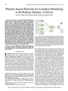
Fig. 1. Cross-sectional view of IGBT modules: (a) wire-bond modules and (b) press-pack modules.
The overview of IGBT modules is categorized with two levels: die and package. This classification is based on the role of dies and packages in IGBT modules. Dies provide the essential function of power semiconductor devices, i.e., control of electrical power, whereas packages provide electrical interconnection, heat dissipation path, and environmental and handling protection.
dies may be limited since most of their mechanisms of diode dies are not wearout failures but overstress failures.
A. IGBT Modules: Die Level The basic structure of IGBT dies was first introduced in the early 1980s [14], [15]. While Si-based IGBTs have been continuously improved [16], [17], wide band-gap semiconductor materials such as SiC and GaN also have drawn attention for the future innovation of IGBTs [18]–[20]. New technologies are also being developed based on the concept of superjunctions [21], [22]. The adoption of improved and innovative IGBT technologies potentially introduces new failure modes and mechanisms, which can complicate the tasks of CM and prognostics. This rapid evolution of IGBT technologies will remain as challenges for the CM and prognostics community. IGBT dies are often packaged with diode dies for some applications such as voltage source converters. Freewheeling diodes can fail under various loading conditions, in particular, during the turn-on transition of IGBTs with a high switching frequency. The failure eventually slows down the switching speed of power converters [23]. Wu et al. [24] presented an overview of catastrophic failures of freewheeling diodes in power electronic circuits. Within the current CM technology, however, CM of diode
B. IGBT Modules: Package Level Two packaging techniques have been used traditionally: wirebond modules and press-pack modules [25]. Cross-sectional views of the two modules are illustrated in Fig. 1. As the most widely used technology for IGBT packaging, wire-bond modules adopt well-established and low-cost aluminum wire bonding technologies to provide electrical connections between the pads on the top of the die and the output terminals [26]. Presspack modules for IGBTs were developed to take advantage of the packaging technology used for thyristors [27]. The advantages and disadvantages of wire-bond modules and press-pack modules are compared in Table I. Several studies [28]–[30] claimed that the implementation of IGBT dies in press-pack modules should guarantee higher reliability. In particular, Scheuermann [31] demonstrated that, under both active and passive thermal cycling, IGBT modules that designed with pressure contacts without solder interconnects outperformed those with conventional wire bond technologies. The packaging techniques for IGBTs have been evolving continuously for further improvements [32]–[37]. It should be noted that the adoption of a new technology to mitigate one failure mechanism often leads to the exposure of another [37], [38].
OH et al.: PHYSICS-OF-FAILURE, CONDITION MONITORING, AND PROGNOSTICS OF IGBT MODULES: A REVIEW
TABLE I COMPARISON BETWEEN WIRE-BOND AND PRESS-PACK MODULES [28], [30], [90], [91] Feature
Symbol
Definition
VC E , o n VG E VG E , th to f f to n Rth Tj
Collector–emitter voltage when the IGBT is on-state Gate–emitter voltage Gate–emitter threshold voltage Duration of the transition from on-state to off-state Duration of the transition from off-state to on-state Thermal resistance from junction to case Junction temperature
Current flow in individual dies can be uneven due to their temperature differences. Conventional (inexpensive)
The possibility of fatigue failure is reduced since wire bond and solder interconnect are substituted with bondless pressure contact [31]. With a redundant design, the module can continuously operate with a single die failure. A failed die can be replaced during planned system services. The plasma formed by a short circuit can be confined inside the module through proper designing. Complicated; for example, deionized water is used. Uneven heat dissipation is reduced by sharing common heat sink blocks; for example, the temperature difference between the hottest and the coldest dies were 6 °C during the heating phase of a power cycle [29]. Current flow in individual dies is “quite homogenous” between individual dies [29]. Unique (expensive)
A ceramic layer itself in the DBC substrate provides the internal insulation. Transient voltage of individual dies varies unless their electrical circuits are perfectly identical.
A die carrier subassembly requires housing for the insulation. Differences in transient voltage of individual dies are reduced since a common inductive path is shared.
Mismatch in CTE can lead to fatigue failure
Single die failure susceptibility
The state (open- or short-circuit) after a single die failure is not defined. It can lead to catastrophic failure of the whole module. An explosion was observed when short-circuit conditions were met [92], [93].
Cooling system Heat dissipation
Current distribution Die mounting Electrical insulation Transient voltage at high switching frequency
TABLE II DEFINITIONS OF PARAMETERS INDICATIVE OF DIE AND PACKAGE DEGRADATION
Press-pack module
Wire-bond module
Power and thermal cycling reliability
Explosion safety
2415
Simple; for example, a heat sink with a cooling fan is used. Large temperature differences between individual dies can occur due to inherent variability in thermal resistance of their solder interconnects and substrates.
III. CM The reliability of IGBT modules has been improved substantially for the past decade and it can be further assured by advanced designs and optimized use of materials. Yet, for safetyor mission-critical applications such as transportation, military, aerospace, and offshore wind power, reliability assessment of IGBT modules during product development may not be sufficient to guarantee the reliability in the field since unpredicted events always happen. According to the industry-wide survey [9], 25% of the responses revealed that the failure/cost ratio (failure cost divided by original system cost) of power conversion systems is very high (i.e., the failure/cost ratio is over 80%). Such failures can result in catastrophic and unrecoverable consequences. The survey showed a strong demand for better ways to handle the reliability of IGBT modules, in particular, for the responders who experienced a high failure/cost ratio. The CM approach, originally developed in other systems such as rotating machines and electrical equipment, was adopted and implemented to further enhance the reliability of power converters in the field, and thus to be able to prevent failures. The CM approach for IGBT modules aims to detect changes in parameters indicative of die and package degradation during operation.
CM techniques are being actively studied in the power electronics technical community. In the following sections, the details of CM techniques for IGBT are described in conjunction with corresponding failure modes and mechanisms. A. CM Parameters and Target Failure Mechanisms The definitions of parameters frequently used in IGBT CM are listed in Table II. The relation between performance parameters such as VCE,on , VGE , and VGE,th and health conditions of IGBT dies have been studied primarily for the development of CM techniques since a shift in those parameters changes the operation of IGBTs in unintended manners, which can directly degrade the performance of the system. Parameters related to switching IGBTs, such as ton and toff , were also studied to avoid a catastrophic failure of IGBTs. It is well known that the junction temperature of IGBTs increases as the condition of IGBTs degraded. Estimation of junction temperature Tj or thermal resistance Rth received some attention during the development of CM techniques. In Table III, the CM parameters are summarized in conjunction with failure modes and mechanisms. Failure modes and mechanisms are dictated by the technology used in IGBT modules [39]. Numerous papers addressed the failure mechanisms of wire-bond modules. Latch-up, dielectric breakdown, bond wire degradation, and solder joint fatigue are the failure mechanisms targeted by the current CM techniques. It is worth noting that a single failure mechanism can induce changes in multiple CM parameters. Not a single CM parameter can be necessary and sufficient to monitor the individual failure mechanisms in IGBTs. B. On-State Collector Emitter Voltage-Based Techniques An IGBT structure has four alternating layers of N-type and P-type regions, which constitute a parasitic thyristor of a PNP transistor and a NPN transistor. The failure occurs when the parasitic thyristor is activated. This failure is irreversible and it is called “latch-up” [40]. Patil et al. [41] conducted thermal overstress tests of IGBT components to induce latch-up failures. The junction temperature was raised beyond the maximum rating of 150 °C by reducing the heat transfer capability of the IGBT components (i.e., removing the heat sink). The IGBT components were subjected to power cycling until the latch-up occurred. The voltage bias across IGBT components was removed
2416
IEEE TRANSACTIONS ON POWER ELECTRONICS, VOL. 30, NO. 5, MAY 2015
TABLE III FAILURE SITES, MECHANISMS, AND CM PARAMETERS
Failure sites Die level
Package level
Die
Bonding wire: bond
Bonding wire: heel Bonding wire: body Solder joint
Failure modes
Failure mechanisms
CM Parameters
Short circuit, burnout, loss of gate control Short circuit, loss of gate control Bond wire liftoff
Latch-up and secondary breakdown
V CE , o n to f f V GE , t h
Patil et al. [41] Brown et al. [53]
Time dependent dielectric breakdown Fatigue and/or reconstruction
VG E VG E , th
Rodriguez et al. [94] Patil et al. [41]
to n to f f
Tounsi et al [48] Xiong et al. [44] Zhou et al. [49] Zhou et al. [50] Smet et al. [42]
Bond wire heel cracking Open wire Wire burnout Solder joint cracks
V CE , o n V GE
References
Fatigue
Stress corrosion Joule heating Fatigue or grain growth
Rth , V CE , o n to f f Low-order harmonics
Patil et al. [41] Tounsi et al. [48] Xiong et al. [44] Xiang et al. [65], [70]
immediately after the latch-up was observed, which prevented a complete failure of the IGBT component. The component was cooled down to ambient and the value of VCE,on was measured. The results indicated that degradation by thermal overstress decreased the values of VCE,on regardless of ambient temperatures. The subsequent failure analysis showed that the VCE,on drop of 8–25% was attributed to die-attach degradation. Bond wires have been recognized as a major failure site in wire-bond power modules [12], [25]. Due to a large coefficient of thermal expansion (CTE) mismatch, temperature swings during cycling induce: 1) stress at the interface between the silicon die and the aluminum wire; and 2) flexure of the heel of the aluminum wire. Smet et al. [42] conducted power cycling tests of wire-bond IGBT modules. Three tests with various minimum and maximum case temperature profiles were performed: 1) 60 and 120 °C; 2) 90 and 150 °C; and 3) 60 and 140 °C. An increase in VCE,on was observed from all three cases degraded by the power cycling. This was attributed to the aging of wire bonds and bond pad metallization. The CM technique provided warnings as early as approximately 86% of the total life when the increase of VCE,on by 3% was assumed to be the fault. Although VCE,on can be considered as a failure precursor for the wire bonding failure, the application of VCE,on to the real-time field monitoring is challenging as discussed in [42]. An increase in VCE,on resulting from the degradation can be overwhelmed by signal noise or disturbance during switching.
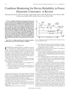
Fig. 2. On-state collector–emitter voltage measurements within an uncertainty of 0.1% [43].
Uncertainty larger than 1% can lead to a significant error in characterizing the health condition of a partially degraded IGBT module, if the failure criterion is assumed to be as small as a 5% increase. To cope with these problems in electric vehicle applications, Ji et al. [43] implemented an analog multiplexer circuit and an advanced CM algorithm. The results of in situ measurements of VCE,on are shown in Fig. 2 [43], where the measurements accuracy of less than 0.1% is evident. Since monitoring of wire bond conditions does not require much time (approximately 0.2 s) as claimed in [43], the method may be applicable when the electrical vehicle stops in red traffic conditions or routine servicing. Practical issues such as the cost and physical dimension of monitoring devices would also have to be considered in actual field applications. Another issue associated with VCE,on -based CM techniques is that VCE,on is affected by both junction temperature and health conditions of IGBT modules. To separate the junction temperature effect from the package degradation effect, Xiong et al. [44] developed a warning system for electric and hybrid vehicle applications that consisted of the hardware architecture and adaptive-algorithm-based software architecture. The “adaptive” nature of the algorithm enabled an individual vehicle to generate its own lookup table about the junction temperature and the corresponding VCE,on . According to their CM strategy, the CM subroutine in the vehicle control system was activated to compare a measured VCE,on value to a reference value in lookup tables immediately after the key-on or key-off of each vehicleuse period, which did not change the normal operation of the vehicle and thus hardly increased the hardware cost of the existing vehicle-drive system. It is worth noting that the trends of VCE,on presented in the literature are not consistent; the value of VCE,on decreased in [41] and [44], whereas it increased in [42] and [43]. The reasons [41]–[43] for the opposite trend during the power cycling tests are summarized in Fig. 3. This implies that CM techniques solely relying on VCE,on may not be dependable when the two failure mechanisms compete with each other and thus the individual effects are nullified. The value of VCE,on is a sum of voltage potentials of individual circuit components between the collector and emitter terminals of wire-bond modules. Contributions of individual circuit components to changes in VCE,on and corresponding failure mechanisms should be evaluated if the value of VCE,on is to be used as a CM parameter.
OH et al.: PHYSICS-OF-FAILURE, CONDITION MONITORING, AND PROGNOSTICS OF IGBT MODULES: A REVIEW
Fig. 3. Two opposite trends in V C E , o n during power cycling tests: the hypotheses that explain (a) decrease and (b) increase.
Fig. 4.
Gate–emitter voltage waveforms during turn-on [49].
Fig. 5.
Equivalent RLC circuit model for IGBT inductive turn-on [52].
2417
C. Gate Emitter Threshold Voltage-Based Techniques An increase of VGE,th was also observed during thermal overstress tests of IGBT components [41]. The results showed that the value of VGE,th increased from zero to 11% over a total of eight samples. The capacitance across the gate and emitter terminals was investigated with respect to the gate voltage; the results supported the hypothesis that the presence of trapped electrons in the gate oxide was the cause of the increase of VGE,th after thermal aging. Bouarroudj et al. [45] also reported an increase of VGE,th by approximately 300 mV when IGBT modules were subjected to the power cycling condition of automotive hybrid traction applications (ambient temperature = 90 °C; and temperature swing = 60 °C). The increase of VGE,th was attributed to gate oxide degradation. Accumulating a sufficient number of defects and traps in the bulk silicon dioxide as well as at the interfaces, gate oxide breakdown can occur, which causes a catastrophic failure [46]. Gate oxide breakdown has been observed during accelerated power cycling testing of IGBT modules [47]. The studies in [41] and [45] showed that a change in VGE,th was an indicator for gate oxide degradation of IGBTs subjected to power cycling, albeit under laboratory conditions. Currently, the use of gate emitter voltage-based techniques for field applications is limited. Measurements of VGE,th interrupt IGBTs’ operation and require to inject external signals to the gate. For online monitoring of VGE,th of IGBT dies in a module, the structure of IGBT modules may have to be modified. D. Switching Time-Based Techniques Switching time-based techniques utilize the change of waveforms including VCE , VGE , ICE , and IGE during turn-on or turn-off [48]. Zhou et al. [49], [50] monitored VGE and IGE waveforms during turn-on to detect bond wire failure. The representative result is shown in Fig. 4 [49], where the difference between two waveforms was visually observable; the increasing rate of VGE of a failed component was faster than that of a healthy one.
Later, a switching time-based technique was developed to avoid catastrophic failure caused by the open- and short-gate in IGBT modules [51], where a fault-detection circuit based on VGE waveform was implemented in the gate drive of induction motor drive systems. It was claimed that the CM technique could prevent the catastrophic failure of an induction motor drive system by detecting imminent failure within a very short time (less than 3 μs). There is room for further improvement since the immediate shutdown of motor drive systems may not be always desirable. An in-depth analysis of voltage and current waveforms during switching of IGBTs was conducted through equivalent RLC circuit modeling and subsequent validation. Fig. 5 shows an equivalent RLC circuit model used in [52]. The bond wires that connected the silicon die to terminal leads were modeled by a resistor and inductor pair. The use of equivalent RLC circuit models helped calculate the change of toff and ton in current and voltage waveforms. Brown et al. [53] defined toff as the amount of time for VCE to increase from 10% to 90% of its final value during turn-off. The study demonstrated the ability to distinguish the difference between aged and healthy IGBT components using online measurements of toff within an operating temperature range of 305–315 K. In Fig. 6 [53], toff of a representative healthy IGBT
2418
Fig. 6.
IEEE TRANSACTIONS ON POWER ELECTRONICS, VOL. 30, NO. 5, MAY 2015
Collector–emitter voltage waveforms during turn-off [53].
component is compared with those of two faulty IGBT components. They claimed that the toff value was an early indicator to latch-up failure caused by damage in the die-attach layer. As mentioned in [53], more work can be done to improve the technique. A diagnostic circuit has to be developed to detect latch-up at the early stage of degradation by continuously monitoring toff in real time. The effect of an operating temperature on the change in toff should be examined since an operating temperature in the field may not be limited to the range of 305–315 K. A further study is required to quantitatively compare accuracy, resolution, processing time, cost, etc., among the switching time-based techniques. E. Temperature-Based Techniques As described in Fig. 1(a), solder layers exist at the interfaces: 1) between the silicon die and the substrate; 2) between the substrate and the base plate; and 3) between the substrate and the terminal leads (or busbar). The repetitive application of thermomechanical loading causes cracking or voiding in the solder layers. These cracks and voids reduce the effective area available for heat dissipation from the silicon die to the heat sink, which increases the thermal resistance in the module, and thus eventually raises the junction temperature. With the increased junction temperature, the die becomes more susceptible to failure mechanisms such as secondary breakdown and catastrophic burnout [54], [55]. Delamination of the metallization layers on a ceramic substrate and brittle fracture of a substrate itself are dominant failure modes of the substrate of wire-bond IGBT modules [56]. Direct assessment of the severity of solder layer damage, i.e., measurements of crack or void sizes, internal thermal resistance, and junction temperature, is not most practical. The estimation of those parameters by monitoring other readilymeasurable parameters is more efficient in terms of cost and time. However, challenges still remain as to how quantitatively the readily measurable parameters can be correlated with the actual solder damage in IGBT modules. The temperature difference between the top and the bottom of a solder layer defines the thermal resistance of the layer for
Fig. 7.
CM technique based on thermal resistance estimation [65].
a given heat transfer rate. Therefore, the thermal resistance can be calculated if the temperatures and the amount of heat generation are known. The heat generation considering the power loss was estimated by building and improving the accuracy of electrothermal models [57]–[61]. Several research [62]–[64] focused more on accurate estimation of the junction temperature, which was considered to be most critical to the assessment of solder joint damage. A simple way for measuring the junction temperature is to place a temperature sensor near the junction [62]. This enables online measurements of the junction temperature without interrupting IGBT operation. However, this technique is invasive and the accuracy of the measurements is affected by the sensor location. Another method is to deduce the junction temperature from measurements of a temperature-sensitive parameter such as VCE,on , which consists of two steps: one is offline characterization of IGBTs under tests and the other is online estimation of the junction temperature using the characterized data and VCE,on measurements [42], [62]. Although a measurement circuit can be embedded in the gate driver without any invasive modification of IGBTs, real-time measurements of VCE,on is still challenging as the switching frequency of IGBTs gets higher and the magnitude of VCE changes rapidly before and after switching. Recently, solder layer damages were monitored by measuring the case and the ambient temperatures and subsequently calculating the additional power loss from the measured temperature changes [65]. The process to estimate the damage used in the study is shown in Fig. 7 [65]. The power loss was first estimated from a thermal model that utilized temperature measurements as inputs. A lookup table that provided the information of power loss in healthy IGBT modules was subsequently incorporated, which enabled the estimation of solder layer damage under various operating conditions. In the analysis, the thermal transient within the module was assumed to be much faster than the variation of the operating point. This assumption may limit the use of the method in wind power and traction applications, where the environmental and operating conditions such as wind speed
OH et al.: PHYSICS-OF-FAILURE, CONDITION MONITORING, AND PROGNOSTICS OF IGBT MODULES: A REVIEW
Fig. 8. Equivalent circuit of modified IGBT module: (a) without and (b) with emitter bond wire liftoff [66].
and power control can change faster than the duration required for IGBT dies to reach their steady-state temperature. F. Other Techniques In the previous sections, we reviewed CM techniques that addressed how to monitor and assess changes in the performance parameters related to the degradation of IGBT components and modules. In real-life power converter applications, extraction of small deviations from the nominal values of the performance parameters is challenging. Furthermore, the mere act of measuring those parameters may change the operational characteristics of the IGBT modules. Several CM techniques, which do not interfere with the operation of IGBT modules, have also been investigated: they include embedded sensor-based, time-domain reflectometry (TDR)-based, and inverter output-based CM techniques [66]–[70]. An embedded sensor-based CM technique was developed to detect bond wire liftoff [66], [67]. As shown in Fig. 8 [66], redundant bond wires are attached to the emitter of the die. Bond wire failure was detected when the resistance between the emitter terminal and the sensor terminal deviated from a nominal value. Although it provided accurate detection of bond wire failure regardless of the operation, the technique required a modification of the original design of IGBT modules and an implementation of the monitoring circuit in a gate driver. A TDR-based approach described in [68] created multiple impedance matrices that identified the defect locations in IGBT modules and the corresponding severity of the defects. Those matrices could be used as a reference to determine the degradation of IGBT power module of interest. This ability to identify the defect locations is a unique advantage of the TDRbased CM technique, which can be achieved by correlating reflected TDR signals with response delay. The TDR-based CM technique should be implemented carefully due to practical issues such as impedance control in electrical circuits, resistance variations at probing interfaces, and electromagnetic interferences.
2419
An inverter output-based CM technique detects changes in the voltage and current outputs of power inverters [69], [70]. Ideally, power inverters are supposed to generate a series of inverter phase pulses with perfectly modulating width and perfectly constant amplitude, which produce an ideal harmonic output. In reality, however, the width and amplitude of pulses are distorted as IGBT modules in a power inverter degrade. Ginart et al. [69] observed high-order oscillatory responses in the voltage amplitudes and currents during switching. This response was related to the changes of parasitic capacitances present in IGBTs after thermoelectrical aging. Another study by Xiang et al. [70] reported changes of low-order harmonics in the output of a voltage-source inverter. This change was attributed to the reduction of the effective area of solder joints, induced by cracks. These harmonics were suppressed by an external control loop, where the control action was used as a CM parameter. IV. BEYOND CM: PROGNOSTICS “Prognostics” is an engineering discipline to predict the health condition at some point in the future and to estimate the RUL under actual usage conditions. If prognostic capabilities become available, the ability to determine RUL permits more flexibility in decision making, while minimizing the risk of failure [71]– [73]. For example, it would be more cost-effective if the continuous operation of offshore wind turbines is not interrupted until the RUL approaches to zero. Prognostics of IGBTs received attention primarily from mission-critical systems such as avionics, high-speed rail, and offshore wind turbines. In such a system, no failure is acceptable until the next maintenance period. In this section, two prognostic approaches for IGBT modules are presented. A. Model-Based Prognostic Approach The model-based prognostic approach relies on PoF models that describe the relationship between lifetime and design parameters, material properties, and loading conditions. Currently, lifetime modeling techniques are utilized to predict fatigue life of wire bonds and solder joints of IGBT modules under cyclic loading conditions. Fatigue life models can be categorized into four groups: stress-based, strain-based, energy-based, and damage-based models. The strain-based model, called the Coffin–Mason equation [74], has been widely used to find the number of cycles to failure of wire bonding under thermomechanical loading [75]–[77]. A damage-based model was also used to predict the cycles to failure of wire bonds in IGBT modules with a temperature swing smaller than 30 °C [78]. Lifetime modeling itself aims primarily to estimate the reliability during product development [79]–[81]. Fatigue models are designed to predict the cycles-to-failure of IGBT modules subjected to repetitive cyclic loading. Failure models are not designed to predict RULs of IGBT modules under “actual” usage conditions. As shown in Fig. 9 [82], the power amplitudes of an offshore wind turbine are not constants but vary in a nonstationary manner. Therefore, additional work is required to predict RULs under “actual” usage conditions.
2420
IEEE TRANSACTIONS ON POWER ELECTRONICS, VOL. 30, NO. 5, MAY 2015
TABLE IV COMPARISON OF CM TECHNIQUES Pros VC E , o n
Useful to detect wire bond degradation or die attach degradation.
VG E , th
Useful to detect gate faults.
t o n or t o f f
Can prevent catastrophic failure in wire bonds and the gate.Useful to detect latch-up failure. Effective to detect solder joint degradation.
Rth
Fig. 9.
Operational data recorded from a wind turbine [82].
Fig. 10. Lifetime estimation model for voltage-source inverters used in wind turbine applications [86].
Fig. 11.
Predicted probability distribution of time-to-failure of IGBTs [87].
There are three practical issues for a fatigue model-based prognostic approach to be applied to real field applications. The first issue is how to accurately convert the environmental and operational loading conditions into thermomechanical stresses. The second issue is how to define and extract the number, the amplitude, and the duration of thermal cycles experienced by
Sensorbased TDR-based
Detects bond wire failure without interfering IGBT operation. Theoretically possible to determine the location of defects.
Inverter outputbased
Does not need any modification of the system.Useful to detect solder joint degradation
Cons Difficult to detect small change from large changes in VC E during fast switching.Can fail when multiple failure mechanisms exist. Interrupts normal operation.Requires external signals to the gate. Can detect only imminent failure.Can fail when multiple failure mechanisms exist. Requires electrothermal and thermomechanical modeling which can be expensive and time consuming. Requires modification of original design of IGBT modules. Difficult to control impedance in circuits.Can be interfered by electromagnetic waves from external sources. Difficult to understand effect of faults in IGBT modules on outputs of the system.
a system, when the system is subjected to a mission (or application) profile. Although several methods were proposed to decompose a mission profile into elementary cycles [83], their accuracy is still unknown. The last issue is how to calculate damages accumulated in wire bonds or solder joints in IGBT modules. Several studies attempted to address these issues encountered in the model-based prognostic approach. Yin et al. [84] constructed a linear equation between the power dissipation and the junction temperature, which simplified the true relationship for real-time calculation. A response surface was also constructed to relate the junction temperature to the plastic strain in the SnAg alloy layer of IGBT modules. For a given profile of power dissipated from the IGBT dies, the junction temperature profile can be calculated in real time with the constructed linear equation and the response surface. The RULs are estimated by incorporating the rainflow counting method [85] and the linear damage accumulation law (i.e., Miner’s rule). The main contribution of the study was to define a potential way to predict RULs of IGBT modules in the actual application environment; yet, it was difficult to verify the prediction accuracy. Recently, Huang and Mawby [86] presented a more practical prognostic method to calculate the lifetime of voltage source inverters for wind turbine applications in real time, assuming solder joint fatigue as a dominant failure mechanism of the selected IGBT modules. The flowchart used to estimate lifetime is shown in Fig. 10 [86]. Lookup tables constructed from offline electrothermal model simulations were used to speed up the online computation of the junction temperature. Then, the lifetime was calculated using the Coffin–Mason equation, the rainflow counting method, and a modified damage accumulation model. It is worth noting that the prediction accuracy has not been proven yet, which delays applications of prognostic approaches to real systems in the field.
OH et al.: PHYSICS-OF-FAILURE, CONDITION MONITORING, AND PROGNOSTICS OF IGBT MODULES: A REVIEW
B. Data-Driven Prognostic Approach The model-based prognostic approach uses knowledge of material properties, product geometry, life cycle loading, and failure models to estimate the life of a product. This approach is useful when failure models that emulate the actual failure mechanism are available. On the other hand, the data-driven prognostic approach does not require specific knowledge of a product. Instead, information about health conditions is extracted from historical data on the performance of a product without relying on failure models, which can be useful when failure models are not available or too complex to formulate. Then, it predicts the lifetime using machine learning techniques, and statistics and probability theory. A particle-filtering-based method provides the probability distribution of RULs, which recursively estimates and updates the probability distribution of life model parameters as additional measurements become available. An example of RUL predictions for IGBTs in power cycling testing is described in Fig. 11 [87]. Patil et al. [88] proposed a prognostic approach for non-punch-through field-stop IGBTs based on Mahalanobis distance and particle filtering methods. In their study, once an anomalous behavior was detected by the Mahalanobis distance method, an algorithm based on particle-filtering was triggered to predict the RUL of an IGBT. V. DISCUSSION ON CM AND PROGNOSTICS The current stage of CM techniques still warrants significant improvements to enhance the applicability to various real-field environments, and thus to be used in routine industry practice. Advantages and disadvantages of CM techniques discussed in Section III are compared in Table IV. It should be noted that not a single CM technique is perfect. Table V summarizes potential failure sites, causes, stresses, modes, and mechanisms in IGBT modules. Based on authors’ experience (thus subjective), mechanisms that are most widely discussed in the literature as well as most frequently reported from the field failures are fatigue, latch-up, electrostatic discharge, radiation-induced effect, and ceramic substrate fracture. Currently available CM techniques addressed only a part of potential failure mechanisms. Further research is encouraged to prevent other failure mechanisms by relevant CM and prognostic techniques. It should be noted that, within the domain of current technology, CM can only be applied to the wearout failure mechanisms. In real field applications, IGBT modules are subjected to various operating and environmental conditions. Variations of switching frequency, duty cycle, load, and temperature would contribute to CM parameter changes even when IGBT modules remain in the same health condition. For example, junction temperature variations change carrier mobility and internal electrical resistance, which is ultimately manifested as variations in onstate collector–emitter voltage output [86]. The CM techniques reviewed in this paper were demonstrated under controlled experimental conditions and may not perform as intended in realoperating conditions. Future research, thus, should address this existing but critical challenge more extensively, namely identi-
2421
fying CM parameters only related to the deterioration of IGBT modules and/or developing advanced CM algorithms to separate the CM parameter changes caused only by IGBT degradation from the complex field signals. During reliability testing of IGBT modules, it is generally observed that multiple failure mechanisms compete with each other, each affecting multiple CM parameters. As discussed in Section III-A, an on-state collector emitter voltage-based technique may fail to detect the degradation of dies or wire bonds as the competing mechanisms cancel the effects each other, which can result in catastrophic consequences. Literature on the development of CM or prognostic techniques for multiple failure mechanisms seems absent. It is suggested that the effect of multiple failure mechanisms on CM parameters should be studied more extensively. If the effects are clearly understood, it is reasonable to expect that CM parameters associated with the corresponding dominant failure mechanisms (i.e., failure precursors) can be determined to help further improve CM and prognostic techniques. In safe- and mission-critical applications, a component is immediately replaced or overhauled before failure, once an anomalous behavior is detected from the component. As a result, failure data are seldom collected from the field, although run-to-failure data are used in the development of CM and prognostic techniques. To overcome the absence of available data, accelerated tests of IGBT modules are often conducted. However, this is time-consuming and expensive. In reality, there are abundant censored (or suspension) field data, which contain information on how long components survive before repair or replacement. Research on how to incorporate censored field data into the development of CM and prognostic techniques would be valuable. Practicality considering measurement accuracy, computational costs, and data storage, etc., should be also evaluated during the course of development of CM and prognostic techniques. Tradeoffs have to be optimized for practical implementation. For example, thermomechanical finite-element method models of IGBT dies can provide accurate predictions of temperature distributions in IGBT modules. However, their computational costs are too high for real-time applications. This is ongoing research actively addressed in the CM community. The use of lookup tables or linear equations could reduce computational costs significantly [84], [86]. Bazzi et al. [89] presented a simple power loss estimation method that relies on data sheet information and measurement of three parameters of IGBTs and diodes without losing much accuracy (errors less than 8%). Prognostic methods are inherently based on a certain set of assumptions and simplifications. The most critical assumption would be failure criteria. As shown in Table VI, most failure criteria found in the literature were typically set for reliability testing, and later verified by failure analyses. If a failure criterion does not reflect the actual failure accurately, the physical interpretation of RUL is prone to produce more uncertainties. It is recommended that future research should address this deficiency in failure criteria. Simplifications for prognostics typically involve an empirical failure model, which often describes complex degradation processes using simple curve fitting. The empirical model is
2422
IEEE TRANSACTIONS ON POWER ELECTRONICS, VOL. 30, NO. 5, MAY 2015
TABLE V FAILURE SITES, CAUSES, STRESSES, MODES, AND MECHANISMS IN IGBT MODULES Failure sites Die level
Die
Causes
r Current spike r Overvoltage between collector and emitter with/without high operating temperature Overvoltage and overcurrent Electrostatic discharge to gate oxide Excessive electric field between gate and emitter High current flow lowering the breakdown voltage Unintended ESD during manufacturing and handling Die exposure to neutrons
r r
r Preexisting defects r Residual stress during manufacturing r Die bending at an elevated Package level
Bond pad Bonding wire: bond
Bonding wire: heel
Bonding wire: body
Solder joint
Ceramic substrate
temperature High temperature, high current flow CTE mismatch between die and wire by temperature excursion Expansion and contraction of bond wire due to temperature change High temperature, high current flow Mechanical loading at high temperature under corrosive environment Short circuit due to various causes, e.g., device latch-up
r CTE mismatch by temperature excursion r Transformation in solder microstructure at high temperature Preexisting defects Residual stress during manufacturing at metal/insulator interface Plate bowing Thermal shock
r r
Stresses
Modes
Mechanisms
Electrical overstress with/without thermal stress
Short circuit, burnout, loss of gate control
Latch-up and secondary breakdown [10], [37], [55], [95]–[97]
Electrical stress Electrical overstress
High leakage current Short circuit, loss of gate control
Hot carrier injection [98] Gate oxide breakdown [46], [47]
Electrical stress
Burnout
Electrical overstress
Burnout
Electromagnetic stress
Burnout,gate rupture
Mechanical or thermomechanical overstress
Die crack
Dynamic avalanche breakdown [99], [100] Electrostatic discharge [10], [101] Radiation-induced effect [102]– [108] Fracture [109], [110]
Thermal overstress, electrical stress Thermomechanical stress
Open circuit Bond wire liftoff
Thermomechanical stress
Bond wire heel cracking
Fatigue [33], [76], [115], [116]
Thermoelectrical stress
Open wire
Electromigration [117]
Thermal, chemical and mechanical stresses
Open wire
Stress corrosion
Thermal, mechanical, chemical, and/or electrical overstress Thermomechanical stress
Wire burnout
Joule heating
Solder joint cracks
Fatigue or grain growth [83], [118]–[120]
Mechanical stress
Shell-like fracture pattern
Brittle fracture [42], [121]
Thermomechanical stress
Delamination
Electrical overstress
Electrical short
Delamination of metallization [56], [122] Partial discharge [123]–[126]
Metallization reconstruction [12] Fatigue [33], [111]–[114]
r
r Poor etching, particle contamination, and voids trapping during manufacturing and assembly Excessive voltage and humidity
r
valid only for the given dataset, and thus it can produce significant uncertainties in RUL predictions for different testing and operating conditions. It is thus recommended for future research that more advanced failure models be developed and implemented to make CM and prognostic techniques more reliable, in turn, prediction of RULs more accurate. VI. CONCLUSION Existing CM and prognostic techniques for IGBT modules were reviewed. It is important to recall that failure mechanisms
are dictated by the technology used in IGBT modules. Within the current technology domain, failures by wearout mechanisms can be prevented by relevant CM and prognostic techniques. CM parameters related to the performance of IGBT modules such as on-state collector–emitter voltage, gate–emitter threshold voltage, switching time lead/delay, and junction-to-case thermal resistance are claimed to be readily measurable or can be indirectly estimated using external equipment. Most of the existing prognostic methods focus on the prediction of RULs for fatigue mechanisms under thermomechanical loading conditions. However, CM and prognostic capabilities that are directly applicable
OH et al.: PHYSICS-OF-FAILURE, CONDITION MONITORING, AND PROGNOSTICS OF IGBT MODULES: A REVIEW
TABLE VI FAILURE CRITERIA OF IGBTS IN LITERATURE Parameter
Threshold
Reference
Rth
20% increase of the initial value
V CE , o n
5% increase of the initial value 10% increase of the initial value ±15% deviation from the nominal value 20% increase of the initial value “Abrupt” increase (not quantified)
I GE , l e a k a g e
Fratelli et al. [127] Coquery and Lallemand [47] Tounsi et al. [48] Coquery and Lallemand [47] Tounsi et al. [48] Ciappa and Fichtner [128] Xiong et al. [44] Patil et al. [88] Coquery and Lallemand [47] Tounsi et al. [48]
to IGBTs are still very limited. The existing methods may have to be modified or significantly improved to be able to provide reliable estimation of the health conditions and the RUL of IGBT modules in real field applications. Based on the literature review, potential research areas were suggested: 1) identification of CM parameters only related to the deterioration of IGBT modules themselves; 2) study on the effect of multiple failure mechanisms on CM parameters; 3) incorporation of censored field data; 4) consideration for the practicality of developed methods; 5) development of relevant failure criteria; and 6) development of advanced failure models. Successful completion of the suggested research topics would make significant contributions toward the ultimate goal of CM and prognostics of IGBT modules, i.e., reliable operation of power electronics.
REFERENCES [1] F. Blaabjerg and K. Ma, “Future on power electronics for wind turbine systems,” IEEE J. Emerg. Sel. Topics Power Electron., vol. 1, no. 3, pp. 139–152, Sep. 2013. [2] J. G. Kassakian and T. M. Jahns, “Evolving and emerging applications of power electronics in systems,” IEEE J. Emerg. Sel. Topics Power Electron., vol. 1, no. 2, pp. 47–58, Jun. 2013. [3] B. K. Bose, “Power electronics and motor drives recent progress and perspective,” IEEE Trans. Power Electron., vol. 56, no. 2, pp. 581–588, Feb. 2009. [4] H. Berg and E. Wolfgang, “Advanced IGBT modules for railway traction applications: Reliability testing,” Microelectron. Rel., vol. 38, pp. 1319– 1323, Jun./Aug. 1998. [5] W. Kanert, “Active cycling reliability of power devices: Expectations and limitations,” Microelectron. Rel., vol. 52, pp. 2336–2341, Sep./Oct. 2012. [6] H. Lu, C. Bailey, and C. Yin, “Design for reliability of power electronics modules,” Microelectron. Rel., vol. 49, pp. 1250–1255, Sep./Nov. 2009. [7] E. E. Kostandyan and J. D. Sorensen, “Physics of failure as a basis for solder elements reliability assessment in wind turbines,” Rel. Eng. Syst. Safety, vol. 108, pp. 100–107, Dec. 2012. [8] S. Yang, D. Xiang, A. Bryant, P. Mawby, L. Ran, and P. Tavner, “Condition monitoring for device reliability in power electronic converters: A review,” IEEE Trans. Power Electron., vol. 25, no. 11, pp. 2734–2752, Nov. 2010. [9] S. Yang, A. Bryant, P. Mawby, D. Xiang, L. Ran, and P. Tavner, “An industry-based survey of reliability in power electronic converters,” IEEE Trans. Ind. Appl., vol. 47, no. 3, pp. 1441–1451, May/Jun. 2011. [10] J.-S. Jeong, S.-H. Hong, and S.-D. Park, “Field failure mechanism and improvement of EOS failure of integrated IGBT inverter modules,” Microelectron. Rel., vol. 47, pp. 1795–1799, Sep./Nov. 2007.
2423
[11] X. Perpina, J. F. Serviere, X. Jorda, A. Fauquet, S. Hidalgo, J. UrrestiIbanez, J. Rebollo, and M. Mermet-Guyennet, “IGBT module failure analysis in railway applications,” Microelectron. Rel., vol. 48, pp. 1427– 1431, Aug./Sep. 2008. [12] M. Ciappa, “Selected failure mechanisms of modern power modules,” Microelectron. Rel., vol. 42, pp. 653–667, Apr./May 2002. [13] B. Lu and S. K. Sharma, “A literature review of IGBT fault diagnostic and protection methods for power inverters,” IEEE Trans. Ind. Appl., vol. 45, no. 5, pp. 1770–1777, Sep./Oct. 2009. [14] B. J. Baliga, M. S. Adler, P. V. Gray, R. P. Love, and N. Zommer, “The insulated gate rectifier (IGR): A new power switching device,” in Proc. Int. Electron Devices Meeting, San Francisco, CA, USA, 1982, pp. 264–267. [15] B. J. Baliga, “Evolution of MOS-bipolar power semiconductor technology,” Proc. IEEE, vol. 76, no. 4, pp. 409–418, Apr. 1988. [16] M. Momose, K. Kumada, H. Wakimoto, Y. Onozawa, A. Nakamori, K. Sekigawa et al., “A 600 V super low loss IGBT with advanced micro-P structure for the next generation IPM,” in Proc. 22nd Int. Symp. Power Semicond. Devices ICs, Hiroshima, Japan, 2010, pp. 379–382. [17] H.-R. Chang, J. Bu, G. Kong, and R. Labayen, “300 A 650 V 70 μm thin IGBT with double-sided cooling,” in Proc. 23rd Int. Symp. Power Semicond. Devices ICs, San Diego, CA, USA, 2011, pp. 320–323. [18] Q. Zhang, R. Callanan, M. K. Das, S.-H. Ryu, A. K. Agarwal, and J. W. Palmour, “SiC power devices for microgrids,” IEEE Trans. Power Electron., vol. 25, no. 12, pp. 2889–2896, Dec. 2010. [19] M. J. Palmer, R. W. Johnson, T. Autry, R. Aguirre, V. Lee, and J. D. Scofield, “Silicon carbide power modules for high-temperature applications,” IEEE Trans. Compon. Packag. Manuf. Technol., vol. 2, no. 2, pp. 208–216, Feb. 2012. [20] J. L. Hudgins, “Power electronic devices in the future,” IEEE J. Emerg. Sel. Topics Power Electron., vol. 1, no. 1, pp. 11–17, Mar. 2013. [21] M. Antoniou, F. Udrea, and F. Bauer, “The superjunction insulated gate bipolar transistor optimization and modeling,” IEEE Trans. Electron Devices, vol. 57, no. 3, pp. 594–600, Mar. 2010. [22] N. Luther-King, M. Sweet, and E. M. S. Narayanan, “Clustered insulated gate bipolar transistor in the super junction concept: The SJTCIGBT,” IEEE Trans. Power Electron., vol. 27, no. 6, pp. 3072–3080, Jun. 2012. [23] M. T. Rahimo and N. Y. A. Shammas, “Freewheeling diode reverserecovery failure modes in IGBT applications,” IEEE Trans. Ind. Appl., vol. 37, no. 2, pp. 661–670, Mar./Apr. 2001. [24] R. Wu, F. Blaabjerg, H. Wang, and M. Liserre, “Overview of catastrophic failures of freewheeling diodes in power electronic circuits,” Microelectron. Rel., vol. 53, pp. 1788–1792, Sep./Nov. 2013. [25] H. Ye, M. H. Lin, and C. Basaran, “Failure modes and FEM analysis of power electronic packaging,” Finite Elements Anal. Des., vol. 38, pp. 601–612, May 2002. [26] T. Komiyama, Y. Chonan, J. Onuki, M. Koizumi, and T. Shigemura, “High-temperature thick Al wire bonding technology for high-power modules,” Japanese J. Appl. Phys. Part 1: Reg. Papers, vol. 41, pp. 5030–5033, Aug. 2002. [27] Y. Takahashi, T. Koga, H. Kirihata, and Y. Seki, “2.5 kV 100 A μ-stack IGBT,” in Proc. 6th Int. Symp. Power Semicond. Devices ICs, Davos, Switzerland, 1994, pp. 25–30. [28] F. J. Wakeman and G. W. Lockwood, “Electromechanical evaluation of a bondless pressure contact IGBT,” IEE Proc.-Circuits Devices Syst., vol. 148, pp. 89–93, Apr. 2001. [29] T. Poller, T. Basler, M. Hernes, S. D’Arco, and J. Lutz, “Mechanical analysis of press-pack IGBTs,” Microelectron. Rel., vol. 52, pp. 2397– 2402, Sep./Oct. 2012. [30] F. Filsecker, R. Alvarez, and S. Bernet, “Comparison of 4.5-kV presspack IGBTs and IGCTs for medium-voltage converters,” IEEE Trans. Ind. Electron., vol. 60, no. 2, pp. 440–449, Feb. 2013. [31] U. Scheuermann, “Reliability challenges of automotive power electronics,” Microelectron. Rel., vol. 49, pp. 1319–1325, 2009. [32] T. Kurosu, K. Khoo, Y. Nakamura, K. Ozaki, N. Ishikawa, and J. Onuki, “Reliability enhancement of thick Al-Cu wire bonds in IGBT modules using Al2Cu precipitates,” Mater. Trans., vol. 53, pp. 453–456, Feb. 2012. [33] Y. Celnikier, L. Benabou, L. Dupont, and G. Coquery, “Investigation of the heel crack mechanism in Al connections for power electronics modules,” Microelectron. Rel., vol. 51, pp. 965–974, May 2011. [34] W. S. Loh, P. A. Agyakwa, C. M. Johnson, T. K. Loh, C. Luechinger, and K. Oftebro, “Thick Al ribbon interconnects: A feasible solution for power devices packaging,” in Proc. 41st Int. Symp. Microelectron., Providence, RI, USA, 2008, pp. 1056–1063.
2424
[35] K. Guth, D. Siepe, J. Gorlich, H. Torwesten, R. Roth, F. Hille, and F. Umbach, “New assembly and interconnects beyond sintering methods,” in Proc. Power Convers. Intell. Motion, Nuremberg, Germany 2010, pp. 232–237. [36] P. Beckedahl, M. Hermann, M. Kind, M. Knebel, J. Nascimento, and A. Wintrich, “Performance comparison of traditional packaging technologies to a novel bond wire-less all sintered power module,” in Proc. Power Convers. Intell. Motion, Nuremberg, Germany, pp. 231–236, 2011. [37] F. Hille, F. Umbach, T. Raker, and R. Roth, “Failure mechanism and improvement potential of IGBT’s short circuit operation,” in Proc. 22nd Int. Symp. Power Semicond. Devices ICs, Hiroshima, Japan, 2010, pp. 33–36. [38] R. Bayerer, “Advanced packaging yields higher performance and reliability in power electronics,” Microelectron. Rel., vol. 50, pp. 1715–1719, Sep./Nov. 2010. [39] G. Coquery, G. Lefranc, T. Licht, R. Lallemand, N. Seliger, and H. Berg, “High temperature reliability on automotive power modules verified by power cycling tests up to 150 degrees C,” Microelectron. Rel., vol. 43, pp. 1871–1876, Sep./Nov. 2003. [40] B. J. Baliga, Fundamentals of Power Semiconductor Devices. New York, NY, USA: Springer Sci., 2008. [41] N. Patil, J. Celaya, D. Das, K. Goebel, and M. Pecht, “Precursor parameter identification for insulated gate bipolar transistor (IGBT) prognostics,” IEEE Trans. Rel., vol. 58, no. 2, pp. 271–276, Jun. 2009. [42] V. Smet, F. Forest, J.-J. Huselstein, A. Rashed, and F. Richardeau, “Evaluation of Vc e monitoring as a real-time method to estimate aging of bond wire-IGBT modules stressed by power cycling,” IEEE Trans. Ind. Electron., vol. 60, no. 7, pp. 2760–2770, Jul. 2013. [43] B. Ji, V. Pickert, W. Cao, and B. Zahawi, “In situ diagnostics and prognostics of wire bonding faults in IGBT modules for electric vehicle drives,” IEEE Trans. Power Electron., vol. 28, no. 12, pp. 5568–5577, Dec. 2013. [44] Y. Xiong, X. Cheng, Z. J. Shen, C. Mi, H. Wu, and V. K. Garg, “Prognostic and warning system for power-electronic modules in electric, hybrid electric, and fuel-cell vehicles,” IEEE Trans. Ind. Electron., vol. 55, no. 6, pp. 2268–2276, Jun. 2008. [45] M. Bouarroudj, Z. Khatir, J. P. Ousten, F. Badel, L. Dupont, and S. Lefebvre, “Degradation behavior of 600 V-200 A IGBT modules under power cycling and high temperature environment conditions,” Microelectron. Rel., vol. 47, pp. 1719–1724, Sep./Nov. 2007. [46] N. Patil, D. Das, K. Goebel, and M. Pecht, “Identification of failure precursor parameters for insulated gate bipolar transistors (IGBTs),” in Proc. 1st Int. Conf. Prognostics Health Manage., Denver, CO, USA, 2008, pp. 1–5. [47] G. Coquery and R. Lallemand, “Failure criteria for long term accelerated power cycling test linked to electrical turn off SOA on IGBT module. A 4000 h test on 1200 A-3300 V module with AlSiC base plate,” Microelectron. Rel., vol. 40, pp. 1665–1670, Aug./Oct. 2000. [48] M. Tounsi, A. Oukaour, B. Tala-Ighil, H. Gualous, B. Boudart, and D. Aissani, “Characterization of high-voltage IGBT module degradations under PWM power cycling test at high ambient temperature,” Microelectron. Rel., vol. 50, pp. 1810–1814, Sep./Nov. 2010. [49] L. Zhou, S. Zhou, and M. Xu, “Investigation of gate voltage oscillations in an IGBT module after partial bond wires lift-off,” Microelectron. Rel., vol. 53, pp. 282–287, Feb. 2013. [50] S. Zhou, L. Zhou, and P. Sun, “Monitoring potential defects in an IGBT module based on dynamic changes of the gate current,” IEEE Trans. Power Electron., vol. 28, no. 3, pp. 1479–1487, Mar. 2013. [51] M. Antonio Rodriguez-Blanco, A. Claudio-Sanchez, D. Theilliol, L. Gerardo Vela-Valdes, P. Sibaja-Teran, L. Hernandez-Gonzalez et al., “A failure-detection strategy for IGBT based on gate-voltage behavior applied to a motor drive system,” IEEE Trans. Ind. Electron., vol. 58, no. 5, pp. 1625–1633, May 2011. [52] A. T. Bryant, L. Lu, E. Santi, J. L. Hudgins, and P. R. Palmer, “Modeling of IGBT resistive and inductive turn-on behavior,” IEEE Trans. Ind. Appl., vol. 44, no. 3, pp. 904–914, May/Jun. 2008. [53] D. W. Brown, M. Abbas, A. Ginart, I. N. Ali, P. W. Kalgren, and G. J. Vachtsevanos, “Turn-off time as an early indicator of insulated gate bipolar transistor latch-up,” IEEE Trans. Power Electron., vol. 27, no. 2, pp. 479–489, Feb. 2012. [54] D. C. Katsis and J. D. vanWyk, “Thermal, mechanical, and electrical study of voiding in the solder die-attach of power MOSFETs,” IEEE Trans. Compon. Packag. Technol., vol. 29, no. 1, pp. 127–136, Mar. 2006.
IEEE TRANSACTIONS ON POWER ELECTRONICS, VOL. 30, NO. 5, MAY 2015
[55] G. Breglio, A. Irace, E. Napoli, M. Riccio, and P. Spirito, “Experimental detection and numerical validation of different failure mechanisms in IGBTs during unclamped inductive switching,” IEEE Trans. Electron Devices, vol. 60, no. 2, pp. 563–570, Feb. 2013. [56] L. Dupont, Z. Khatir, S. Lefebvre, and S. Bontemps, “Effects of metallization thickness of ceramic substrates on the reliability of power assemblies under high temperature cycling,” Microelectron. Rel., vol. 46, pp. 1766–1771, 2006. [57] M. Rencz and V. Szekely, “Studies on the nonlinearity effects in dynamic compact model generation of packages,” IEEE Trans. Compon. Packag. Technol., vol. 27, no. 1, pp. 124–130, Mar. 2004. [58] Y. Tang, B. Wang, M. Chen, and B. Liu, “Simulation model and parameter extraction of field-stop (FS) IGBT,” Microelectron. Rel., vol. 52, pp. 2920–2931, Dec. 2012. [59] O. S. Senturk, L. Helle, S. Munk-Nielsen, P. Rodriguez, and R. Teodorescu, “Converter structure-based power loss and static thermal modeling of the press-pack IGBT three-level ANPC VSC applied to multi-MW wind turbines,” IEEE Trans. Ind. Appl., vol. 47, no. 6, pp. 2505–2515, Nov./Dec. 2011. [60] A. Bryant, N.-A. Parker-Allotey, D. Hamilton, I. Swan, P. A. Mawby, T. Ueta et al., “A fast loss and temperature simulation method for power converters, part I: Electrothermal modeling and validation,” IEEE Trans. Power Electron., vol. 27, no. 1, pp. 248–257, Jan. 2012. [61] O. S. Senturk, L. Helle, S. Munk-Nielsen, P. Rodriguez, and R. Teodorescu, “Power capability investigation based on electrothermal models of press-pack IGBT three-level NPC and ANPC VSCs for multimegawatt wind turbines,” IEEE Trans. Power Electron., vol. 27, no. 7, pp. 3195–3206, Jul. 2012. [62] Y.-S. Kim and S.-K. Sul, “On-line estimation of IGBT junction temperature using on-state voltage drop,” in Proc. Ind. Appl. Conf., St. Louis, MO, USA, 1998, pp. 853–859. [63] D. A. Murdock, J. E. R. Torres, J. J. Connors, and R. D. Lorenz, “Active thermal control of power electronic modules,” IEEE Trans. Ind. Appl., vol. 42, no. 2, pp. 552–558, Mar./Apr. 2006. [64] M. Musallam and C. M. Johnson, “Real-time compact thermal models for health management of power electronics,” IEEE Trans. Power Electron., vol. 25, no. 6, pp. 1416–1425, Jun. 2010. [65] D. Xiang, L. Ran, P. Tavner, A. Bryant, S. Yang, and P. Mawby, “Monitoring solder fatigue in a power module using case-above-ambient temperature rise,” IEEE Trans. Ind. Appl., vol. 47, no. 6, pp. 2578–2591, Nov./Dec. 2011. [66] J. Lehmann, M. Netzel, R. Herzer, and S. Pawel, “Method for electrical detection of bond wire liftoff for power semiconductors,” in Proc. 15th Int. Symp. Power Semicond. Devices ICs, Cambridge, U.K., 2003, pp. 333–336. [67] B. Ji, V. Pickert, N. Zahawi, and M. Zhang, “In situ bond wire health monitoring circuit for IGBT power modules,” in Proc. 6th IET Int. Conf. Power Electron. Mach. Drives, Bristol, U.K., 2012, pp. 1–6. [68] M. S. Nasrin and F. H. Khan, “Real time monitoring of aging process in power converters using the SSTDR generated impedance matrix,” in Proc. 28th Annu. IEEE Appl. Power Electron. Conf. Expo., Long Beach, CA, USA, 2013, pp. 1199–1205. [69] A. E. Ginart, D. Brown, P. W. Kalgren, and M. J. Roemer, “Online ringing characterization as a diagnostic technique for IGBTs in power devices,” IEEE Trans. Instrum. Meas., vol. 58, no. 7, pp. 2290–2299, Jul. 2009. [70] D. Xiang, L. Ran, P. Tavner, S. Yang, A. Bryant, and P. Mawby, “Condition monitoring power module solder fatigue using inverter harmonic identification,” IEEE Trans. Power Electron., vol. 27, no. 1, pp. 235–247, Jan. 2012. [71] G. Haddad, P. A. Sandborn, and M. G. Pecht, “An options approach for decision support of systems with prognostic capabilities,” IEEE Trans. Rel., vol. 61, no. 4, pp. 872–883, Dec. 2012. [72] D. Goodman, J. Hoffmeister, and J. Judkins, “Electronic prognostics for switched mode power supplies,” Microelectron. Rel., vol. 47, pp. 1902–1906, Dec. 2007. [73] N. M. Vichare and M. G. Pecht, “Prognostics and health management of electronics,” IEEE Trans. Compon. Packag. Technol., vol. 29, no. 1, pp. 222–229, Mar. 2006. [74] S. S. Manson, “Behaviour of materials under conditions of thermal stress,” Nat. Advisory Committee for Aeronautics, Washington, DC, USA, Tech. Rep. 1170, 1954.
OH et al.: PHYSICS-OF-FAILURE, CONDITION MONITORING, AND PROGNOSTICS OF IGBT MODULES: A REVIEW
[75] M. Held, P. Jacob, G. Nicoletti, P. Scacco, and M.-H. Poech, “Fast power cycling test for insulated gate bipolar transistor modules in traction application,” Int. J. Electron., vol. 86, pp. 1193–1204, 1999. [76] S. Ramminger, N. Seliger, and G. Wachutka, “Reliability model for Al wire bonds subjected to heel crack failures,” Microelectron. Rel., vol. 40, pp. 1521–1525, Aug./Oct. 2000. [77] K. C. Norris and A. H. Landzberg, “Reliability of controlled collapse interconnections,” IBM J. Res. Develop., vol. 13, pp. 266–271, May 1969. [78] K. Sasaki, N. Iwasa, T. Kurosu, K. Saito, Y. Koike, Y. Kamita et al., “Thermal and structural simulation techniques for estimating fatigue life of an IGBT module,” in Proc. 20th Int. Symp. Power Semicond. Devices IC’s, Orlando, FL, USA, 2008, pp. 181–184. [79] R. Bayerer, T. Herrmann, T. Licht, J. Lutz, and M. Feller, “Model for power cycling lifetime of IGBT modules-various factors influencing lifetime,” in Proc. 5th Int. Conf. Integr. Power Syst., Nuremberg, Germany, 2008, pp. 1–6. [80] R. Jones and P. Waite, “Optimised converter for multi-MW direct drive permanent magnet wind turbines,” in Proc. 14th Eur. Conf. Power Electron. Appl., Birmingham, U.K., 2011, pp. 1–10. [81] L. Wei, R. J. Kerkman, R. A. Lukaszewski, H. Lu, and Z. Yuan, “Analysis of IGBT power cycling capabilities used in doubly fed induction generator wind power system,” IEEE Trans. Ind. Appl., vol. 47, no. 4, pp. 1794–1801, Jul./Aug. 2011. [82] J. M. Ha, S. Choi, B. D. Youn, B. Han, and H. Oh, “A strategic study on data classification and management for optimal condition monitoring system in wind turbines,” J. Wind Energy, vol. 4, pp. 25–33, 2013. [83] M. Ciappa, F. Carbognani, and W. Fichtner, “Lifetime prediction and design of reliability tests for high-power devices in automotive applications,” IEEE Trans. Device Mater. Rel., vol. 3, no. 4, pp. 191–196, Dec. 2003. [84] C. Y. Yin, H. Lu, M. Musallam, C. Bailey, and C. M. Johnson, “A physics-of-failure based prognostic method for power modules,” in Proc. 10th Electron. Packag. Technol. Conf., Singapore, 2008, pp. 1190–1195. [85] M. Matsuishi and T. Endo, “Fatigue of metals subjected to varying stress,” in Proc. Kyushu District Meeting, 1968, pp. 37–40. [86] H. Huang and P. A. Mawby, “A lifetime estimation technique for voltage source inverters,” IEEE Trans. Power Electron., vol. 28, no. 8, pp. 4113– 4119, Aug. 2013. [87] B. Saha, J. R. Celaya, P. F. Wysocki, and K. F. Goebel, “Towards prognostics for electronics components,” in Proc. IEEE Aerospace Conf., Big Sky, MT, 2009, pp. 1–7. [88] N. Patil, D. Das, and M. Pecht, “A prognostic approach for non-punch through and field stop IGBTs,” Microelectron. Rel., vol. 52, pp. 482–488, Mar. 2012. [89] A. M. Bazzi, P. T. Krein, J. W. Kimball, and K. Kepley, “IGBT and diode loss estimation under hysteresis switching,” IEEE Trans. Power Electron., vol. 27, no. 3, pp. 1044–1048, Mar. 2012. [90] S. Bernet, “Recent developments of high power converters for industry and traction applications,” IEEE Trans. Power Electron., vol. 15, no. 6, pp. 1102–1117, Nov. 2000. [91] A. Morozumi, K. Yamada, T. Miyasaka, S. Sumi, and Y. Seki, “Reliability of power cycling for IGBT power semiconductor modules,” IEEE Trans. Ind. Appl., vol. 39, no. 3, pp. 665–671, May/Jun. 2003. [92] S. Gekenidis, E. Ramezani, and H. Zeller, “Explosion tests on IGBT high voltage modules,” in Proc. 11th Int. Symp. Power Semicond. Devices ICs, Toronto, Canada, 1999, pp. 129–132. [93] F. Richardeau, Z. Dou, E. Sarraute, J.-M. Blaquiere, and D. Flumian, “Comparison of IGBT short-circuit failure “ohmic mode”: Epoxy molded package versus silicone gel module for new fail-safe and interruptible power converters,” Microelectron. Rel., vol. 51, pp. 1919–1926, Sep./Nov. 2011. [94] M. A. Rodriguez, A. Claudio, D. Theilliol, and L. G. Vela, “A new fault detection technique for IGBT based on gate voltage monitoring,” in Proc. IEEE Power Electron. Spec. Conf., Orlando, FL, USA, 2007, pp. 1001–1005. [95] X. Perpina, J.-F. Serviere, J. Urresti-Ibanez, I. Cortes, X. Jorda, S. Hidalgo et al., “Analysis of clamped inductive turnoff failure in railway traction IGBT power modules under overload conditions,” IEEE Trans. Ind. Electron., vol. 58, no. 7, pp. 2706–2714, Jul. 2011. [96] A. Benmansour, S. Azzopardi, J. C. Martin, and E. Woirgard, “Trench IGBT failure mechanisms evolution with temperature and gate resistance under various short-circuit conditions,” Microelectron. Rel., vol. 47, pp. 1730–1734, Sep./Nov. 2007.
2425
[97] H. Y. Long, N. Luther-King, M. R. Sweet, and E. M. S. Narayanan, “Numerical evaluation of the short-circuit performance of 3.3-kV CIGBT in field-stop technology,” IEEE Trans. Power Electron., vol. 27, no. 5, pp. 2673–2679, May 2012. [98] A. Maouad, A. Hoffmann, A. Khoury, and J. P. Charles, “Characterization of high-density current stressed IGBTs and simulation with an adapted SPICE sub-circuit,” Microelectron. Rel., vol. 40, pp. 973–979, Jun. 2000. [99] M. T. Rahimo, D. J. Chamund, and N. Y. A. Shammas, “Analysis of the IGBT/freewheeling diode switching behaviour during turn-on in hard switching applications,” in Proc. 7th Int. Conf. Power Electron. Variable Speed Drives, London, U.K., 1998, pp. 381–386. [100] T. Ogura, H. Ninomiya, K. Sugiyama, and T. Inoue, “Turn-off switching analysis considering dynamic avalanche effect for low turn-off loss highvoltage IGBTs,” IEEE Trans. Electron Devices, vol. 51, no. 4, pp. 629– 635, Apr. 2004. [101] P. Wysocki, V. Vashchenko, J. Celaya, S. Saha, and K. Goebel, “Effect of electrostatic discharge on electrical characteristics of discrete electronic components,” in Proc. Annu. Conf. Prognostics Health Manag. Soc., San Diego, CA, USA, 2009, pp. 1–10. [102] D. L. Oberg, J. L. Wert, E. Normand, P. P. Majewski, and S. A. Wender, “First observations of power MOSFET burnout with high energy neutrons,” IEEE Trans. Nucl. Sci., vol. 43, no. 6, pp. 2913–2920, Dec. 1996. [103] E. Normand, J. L. Wert, D. L. Oberg, P. P. Majewski, P. Voss, and S. A. Wender, “Neutron-induced single event burnout in high voltage electronics,” IEEE Trans. Nucl. Sci., vol. 44, no. 6, pp. 2358–2366, Dec. 1997. [104] G. Soelkner, W. Kaindl, H. J. Schulze, and G. Wachutka, “Reliability of power electronic devices against cosmic radiation-induced failure,” Microelectron. Rel., vol. 44, pp. 1399–1406, Sep./Nov. 2004. [105] A. D. Touboul, L. L. Foro, F. Wrobel, K. Guetarni, J. Boch, and F. Saigne, “Neutrons-induced IGBT failure: Effects of the number of tested devices on the cross section calculation,” IEEE Trans. Nucl. Sci., vol. 60, no. 4, pp. 2392–2396, Aug. 2013. [106] A. Griffoni, J. van Duivenbode, D. Linten, E. Simoen, P. Rech, L. Dilillo et al., “Neutron-induced failure in silicon IGBTs, silicon super-junction and SiC MOSFETs,” IEEE Trans. Nucl. Sci., vol. 59, no. 4, pp. 866–871, Aug. 2012. [107] A. D. Touboul, L. Foro, F. Wrobel, and F. Saigne, “On the reliability assessment of trench fieldstop IGBT under atmospheric neutron spectrum,” Microelectron. Rel., vol. 52, pp. 124–129, Jan. 2012. [108] S. Nishida, T. Shoji, T. Ohnishi, T. Fujikawa, N. Nose, M. Ishiko et al., “Cosmic ray ruggedness of IGBTs for hybrid vehicles,” in Proc. 22nd Int. Symp. Power Semicond. Devices ICs, Hiroshima, Japan, 2010, pp. 129–132. [109] W. Wu, M. Held, P. Jacob, P. Scacco, and A. Birolini, “Investigation on the long term reliability of power IGBT modules,” in Proc. Int. Symp. Power Semicond. Devices ICs, Yokohama, Japan, 1995, pp. 443–448. [110] M. Glavanovics, T. Detzel, and K. Weber, “Impact of thermal overload operation on wirebond and metallization reliability in smart power devices,” in Proc. 34th Eur. Solid-State Device Res. Conf., Leuven, Belgium, 2004, pp. 273–276. [111] T. Y. Hung, S. Y. Chiang, C. J. Huang, C. C. Lee, and K. N. Chiang, “Thermal-mechanical behavior of the bonding wire for a power module subjected to the power cycling test,” Microelectron. Rel., vol. 51, pp. 1819–1823, Sep./Nov. 2011. [112] P. A. Agyakwa, M. R. Corfield, L. Yang, J. F. Li, V. M. F. Marques, and C. M. Johnson, “Microstructural evolution of ultrasonically bonded high purity Al wire during extended range thermal cycling,” Microelectron. Rel., vol. 51, pp. 406–415, Feb. 2011. [113] V. Smet, F. Forest, J.-J. Huselstein, F. Richardeau, Z. Khatir, S. Lefebvre et al., “Ageing and failure modes of IGBT modules in high-temperature power cycling,” IEEE Trans. Ind. Electron., vol. 58, no. 10, pp. 4931– 4941, Oct. 2011. [114] H. Medjahed, P.-E. Vidal, and B. Nogarede, “Thermo-mechanical stress of bonded wires used in high power modules with alternating and direct current modes,” Microelectron. Rel., vol. 52, pp. 1099–1104, Jun. 2012. [115] K. Meyyappan, P. McCluskey, and P. Hansen, “Wire fatigue models for power electronic modules,” in Proc. ASME Int. Mech. Eng. Congr. Expo., Washington, DC, USA, 2003, pp. 257–265. [116] Y. Celnikier, L. Dupont, E. Herve, G. Coquery, and L. Benabou, “Optimization of wire connections design for power electronics,” Microelectron. Rel., vol. 51, pp. 1892–1897, Sep./Nov. 2011.
2426
[117] Failure Mechanisms and Models for Semiconductor Devices: JEP122E, JEDEC Solid State Technology Association, Arlington, VA, USA, 2009. [118] L. Feller, S. Hartmann, and D. Schneider, “Lifetime analysis of solder joints in high power IGBT modules for increasing the reliability for operation at 150 degrees C,” Microelectron. Rel., vol. 48, pp. 1161–1166, Aug./Sep. 2008. [119] E. E. Kostandyan and K. Ma, “Reliability estimation with uncertainties consideration for high power IGBTs in 2.3 MW wind turbine converter system,” Microelectron. Rel., vol. 52, pp. 2403–2408, Sep./Oct. 2012. [120] A. Micol, C. Martin, O. Dalverny, M. Mermet-Guyennet, and M. Karama, “Reliability of lead-free solder in power module with stochastic uncertainty,” Microelectron. Rel., vol. 49, pp. 631–641, Jun. 2009. [121] P. Dietrich, “Trends in automotive power semiconductor packaging,” Microelectron. Rel., vol. 53, pp. 1681–1686, Sep./Nov. 2013. [122] G. Mitic, R. Beinert, P. Klofac, H. J. Schultz, and G. Lefranc, “Reliability of AlN substrates and their solder joints in IGBT power modules,” Microelectron. Rel., vol. 39, pp. 1159–1164, Jun./Jul. 1999. [123] J.-H. Fabian, S. Hartmann, and A. Hamidi, “Analysis of insulation failure modes in high power IGBT modules,” in Proc. Conf. Rec. 40th IAS Annu. Meeting IEEE Ind. Appl. Conf., Kowloon, Hong Kong, 2005, pp. 799– 805. [124] G. Mitic and G. Lefranc, “Localization of electrical insulation and partialdischarge failures of IGBT modules,” IEEE Trans. Ind. Appl., vol. 38, no. 1, pp. 175–180, Jan./Feb. 2002. [125] N. Wang, I. Cotton, and K. Evans, “Impact of thermal cycling in humid environments on power electronic modules,” IEEE Trans. Compon. Packag. Manuf. Technol., vol. 2, no. 7, pp. 1085–1091, Jul. 2012. [126] T. A. T. Vu, J.-L. Auge, and O. Lesaint, “Low temperature partial discharge properties of silicone gels used to encapsulate power semiconductors,” in Proc. Annu. Report Conf. Electr. Insul. Dielectr. Phenom., Virginia Beach, VA, USA, 2009, pp. 421–424. [127] L. Fratelli, G. Giannini, B. Cascone, and G. Busatto, “Reliability test of power IGBTs for railway traction,” in Proc. Conf. Power Electron. Appl., Lausanne, Switzerland, 1999, pp. 1–9. [128] M. Ciappa and W. Fichtner, “Lifetime prediction of IGBT modules for traction applications,” in Proc. 38th Annu. IEEE Int. Relia. Phys. Symp., San Jose, CA, USA, 2000, pp. 210–216. Hyunseok Oh (M’13) received the B.S. degree from Korea University, Seoul, Republic of Korea, in 2004, the M.S. degree from KAIST, Daejeon, Republic of Korea, in 2006, and the Ph.D. degree from the University of Maryland, College Park, MD, USA, in 2012. He is a Postdoctoral Research Associate in the Laboratory for Optomechanics and Micro/Nano Semiconductor/Photonics Systems, Center for Advanced Life Cycle Engineering, University of Maryland. From 2006 to 2007, he was with the Hyundai MOBIS Technical Research Institute as a Research Engineer. His current research area includes prognostics and health management and model verification and validation. Dr. Oh received the A. James Clark Fellowship (2007). He was recognized as winner of the IEEE PHM data challenge competition (2012). Bongtae Han received his B.S. and M.S. degrees from Seoul National University in 1981 and 1983, respectively, and his Ph.D. degree in Engineering Mechanics from Virginia Tech in 1991. He is currently a Keystone Professor of engineering and the Director of Electronic Products and Systems Division, Mechanical Engineering Department, University of Maryland, College Park, MD, USA. He is directing the Laboratory for Optomechanics and Micro/Nano Semiconductor/Photonics Systems, Center for Advanced Life Cycle Engineering. He has coauthored a text book entitled High Sensitivity Moir´e: Experimental Analysis for Mechanics and Materials (New York, NY, USA: Springer-Verlag, 1997) and edited two books. He has published 11 book chapters and more than 150 journal and conference papers in the field of microelectronics and experimental mechanics. He holds two US patents and four invention disclosures. Dr. Han received the IBM Excellence Award for Outstanding Technical Achievements in 1994. He was a recipient of the 2002 Brewer Award, presented at the Annual Conference of the SEM in Emerging Technologies. His publication awards include the Year 2004 Best Paper Award of the IEEE TRANSACTIONS
IEEE TRANSACTIONS ON POWER ELECTRONICS, VOL. 30, NO. 5, MAY 2015
ON COMPONENTS AND PACKAGING TECHNOLOGIES, and the Gold Award (best paper in the Analysis and Simulation session) at the 1st Samsung Technical Conference in 2004. He served as an Associate Technical Editor for Experimental Mechanics, from 1999 to 2001, and has been serving as an Associate Technical Editor for Journal of Electronic Packaging, Transaction of the ASME since 2003. He was elected a Fellow of the Society for Experimental Mechanics and the American Society for Mechanical Engineers in 2006 and 2007, respectively.
Patrick McCluskey (M’91) received the Ph.D. degree in materials science and engineering from Lehigh University, Bethlehem, PA, USA, in 1991. He is a Professor of mechanical engineering at the University of Maryland, College Park, MD, USA. He conducts research in the Center for Advanced Life Cycle Engineering focusing in the areas of thermal management, reliability, and packaging of electronic systems for use in extreme temperature environments and high-power applications. He has authored or coauthored more than 100 technical articles and three books, including High Temperature Electronics (New York, NY, USA: Springer, 2011). Dr. McCluskey is a Fellow of the International Microelectronics and Packaging Society (IMAPS), and is a member of American Society for Mechanical Engineers and SAE. He has served as the Technical Chairman of the IMAPS International High Temperature Electronic Conference and Exhibition (HiTEC) and is on the organizing committee for the HiTEN. He is an Associate Editor of the IEEE TRANSACTIONS ON COMPONENTS AND PACKAGING.
Changwoon Han received the B.Sc. and M.Sc. degrees from Seoul National University, Seoul, Republic of Korea, in 1993 and 1995, respectively, and the Ph.D. degree from the University of Maryland, College Park, MD, USA, in 2005, all in mechanical engineering. He is a Senior Research Engineer of the Components & Material Physics Research Center, Korea Electronics Technology Institute, Seongnam, Republic of Korea. His research interests include physicsof-failure-based accelerated life tests, prognostics and health monitoring, design-for-reliability, interconnection durability, and photomechanics.
Byeng D. Youn received the B.S. degree from Inha University, Incheon, South Korea, in 1996, the M.S. degree from KAIST, Daejeon, Republic of Korea, in 1998, and the Ph.D. degree from the University of Iowa, Iowa City, IA, USA, in 2001. He is an Associate Professor of mechanical and aerospace engineering at Seoul National University (SNU), Seoul, Republic of Korea. Before joining SNU, he was an Assistant Professor in the Department of Mechanical Engineering, University of Maryland, College Park. His research goal is to develop rational reliability and design methods based on mathematics, physics, and statistics for use in complex engineered systems, mainly focused on energy systems. His current research includes reliability-based design, prognostics and health management (PHM), energy harvester design, and virtual product testing. Dr. Youn’s dedication and efforts in research have garnered substantive peer recognition resulting in four notable awards including the ASME IDETC Best Paper Awards (2001 and 2008), the ISSMO/Springer Prize for a Young Scientist (2005), the IEEE PHM Competition Winner (2014), etc.