Aug 23, 2007 - with the ideas of morphing and registration from image processing. ..... formulation tries to balance the conflicting objectives of good approximation .... on the boundary of the domain D, the location of A is constrained within D, ...
arXiv:0705.3693v4 [math.DS] 23 Aug 2007
Morphing Ensemble Kalman Filters Jonathan D. Beezley and Jan Mandel Center for Computational Mathematics, University of Colorado at Denver and Health Sciences Center, Denver, CO, and Mesoscale and Microscale Meteorology Division, National Center for Atmospheric Research, Boulder, CO February 5, 2008
Abstract A new type of ensemble filter is proposed, which combines an ensemble Kalman filter (EnKF) with the ideas of morphing and registration from image processing. This results in filters suitable for nonlinear problems whose solutions exhibit moving coherent features, such as thin interfaces in wildfire modeling. The ensemble members are represented as the composition of one common state with a spatial transformation, called registration mapping, plus a residual. A fully automatic registration method is used that requires only gridded data, so the features in the model state do not need to be identified by the user. The morphing EnKF operates on a transformed state consisting of the registration mapping and the residual. Essentially, the morphing EnKF uses intermediate states obtained by morphing instead of linear combinations of the states.
1
Introduction
The research reported here has been motivated by data assimilation into wildfire models (Mandel et al., 2006). Wildfire modeling presents a challenge to data assimilation because of non-Gaussian probability distributions centered around the burning and not burning states, and because of movements of thin reaction fronts with sharp interfaces. This work is a part of an effort to build a Dynamic Data Driven Application System (DDDAS, Darema (2004)) for wildfires (Mandel et al., 2007). Data assimilation is one of the building blocks of the DDDAS concept, which involves a symbiotic network of computer simulations and sensors. The standard Ensemble Kalman Filter (EnKF) approach (Evensen, 2003) fails for highly nonlinear problems that have solutions with coherent features, such as firelines, rain fronts, or vortices, because it is limited to a linear update of state. This can be ameliorated to some degree by penalization of nonphysical states (Johns and Mandel, 2005), localization of EnKF (Anderson, 2003; Ott et al., 2004), and employing the location of the feature as an observation function (Chen and Snyder, 2007), but the basic problem remains: EnKF works only when the increment in the location of the feature is small (Chen and Snyder, 2007). EnKF analysis formulas are based on the assumption that all probability distribution involved are Gaussian, so even if an ensemble can approximate non-Gaussian distribution, the closer the system state distribution is to Gaussian the better. One mechanism how non-Gaussian distributions arise in strongly nonlinear systems is by evolution of coherent features. While the location and the size of the feature may have an error distribution that is approximately Gaussian, this is not 1
necessarily the case for the value of the state at a given point. E.g., the typical probability density of the temperature at a point near the reaction region in a wildfire model is concentrated around the burning and the ambient temperature (Fig. 4a). There is clearly a need to adjust the simulation state by distorting the simulation state in space rather than employing an additive correction to the state. Therefore, alternative error models that include the position of features were considered in the literature (Hoffman et al., 1995; Davis et al., 2006) and a number of works emerged that achieve more efficient movement of features by using a spatial transformation as the field to which additive corrections are made, such as a transformation of the space by a global low order polynomial mapping to achieve alignment (Alexander et al., 1998), and two-step models to use alignment as preprocessing to an additive correction (Lawson and Hansen, 2005; Ravela et al., 2007). Moving and stretching one given image to become another given image is known in image processing as registration (Brown, 1992). Once the two images are registered, one can easily create intermediate images, which is known as morphing. The essence of the new method described here is to replace the linear combinations of states in an ensemble filter by intermediate states obtained by morphing. This method provides additive and position correction in a single step. For the analysis step (the Bayesian update), the state is transformed into an extended state consisting of additive and position components. After the analysis step, the state is converted back and advanced in time. The purpose of this article is to demonstrate the potential of this approach. The paper is organized as follows. In Section 2, we briefly recall data assimilation by EnKF but we do not present the formulation of the EnKF in detail and refer to the literature instead. In Section 3, we describe image morphing and the automatic registration algorithm used. Section 4 contains the formulation of the morphing EnKF. Numerical results on a wildfire model problem are reported in Section 5. Section 6 contains the conclusion and a discussion of future extensions.
2
Data Assimilation and Ensemble Filters
The purpose of data assimilation is to estimate the system state using all data available up to the current time. A discrete filter, considered here, works by advancing in time a probability distribution of the model state until a given analysis time. At the analysis time, the probability distribution, now called the prior or the forecast, is modified by accounting for the data, which are considered to be observed at that time. The new probability distribution, called the posterior or the analysis, is given by the Bayes theorem, pa (u) ∝ p (d|u) pf (u) ,
(1)
where ∝ means proportional, u is the model state, pf (u) is the forecast probability density, pa (u) is the analysis probability density, d is the data, and p (d|u) is the data likelihood. The data likelihood is the density of the probability that the data value is d assuming that the state is u. Assuming an additive data error model, the data likelihood is found from the probability density pε of data error, which is assumed to be known (every measurement must be accompanied by an error estimate), and from an observation function h, by p (d|u) = pε (d − h (u)) .
(2)
The value h (u) of the observation function is what the correct value of the data would be if the model state u were exact. For a tutorial on data assimilation, see Kalnay (2003). The well-known Kalman filter (Kalman, 1960) reduces the Bayesian update (1) to linear algebra in the case when all probability distributions are Gaussian. The Kalman filter must advance the 2
covariance of state, which is possible only when the model is linear, and it is computationally very expensive. The EnKF (Evensen, 1994; Houtekamer and Mitchell, 1998) approximates the P probability distribution by the empirical measure N1 N δ u i , where ui are members of an ensemble i=1 of simulations states, and δu denotes the Dirac delta measure concentrated at u. Each ensemble member is advanced in time between the Bayesian updates independently. The EnKF approximates the mean and the covariance of the forecast by the mean and the covariance of the ensemble, while still making the assumption that all probability distributions are Gaussian. The EnKF works by forming the analysis ensemble as linear combinations of the forecast ensemble, and the Bayesian update is implemented by linear algebra operating on the matrix created from ensemble members as columns. This allows an efficient implementation using high-performance matrix operations. We have used the EnKF version from Burgers et al. (1998), but any other variant could be used as well. For surveys of EnKF techniques, see Evensen (2007) and Tippett et al. (2003).
3
Registration, Warping, and Morphing
In this section, we build the tools from image processing that we are going to use for the morphing EnKF later in Section 4. The registration problem in image processing is to find a spatial mapping that turns two given images into each other (Brown, 1992). Classical registration requires the user to pick manually points in the two images that should be mapped onto each other, and the registration mapping is interpolated from that. Here we are interested in a fully automatic registration procedure that does not require any user input. The specific feature or objects, such as fire fronts or hurricane vortices, do not need to be specified. The method takes as input only the pixel values in an image (i.e., gridded arrays). Of course, for the method to work well, the images being registered should be sufficiently similar.
3.1
Notation
We will find it useful to use mappings as a convenient notation, so we review few basics in an informal manner. The symbol “7→” is read “maps to”, and we sometimes find it convenient to write A : z 7→ w instead of A (z) = w. The domain of a mapping A is the set of its arguments z such that A (z) is defined. For two mappings A and B, their composition A ◦ B is defined by A ◦ B : z 7→ A (B (z)); I is the identity mapping defined by I : z 7→ z (for all z from its domain); and the inverse A−1 of A is a mapping such that A−1 ◦ A = I and A ◦ A−1 = I. A real function on a domain D is also a mapping, namely one that maps D into the reals, R. Given two mappings A and B from the same domain into the same linear space (say, R or Rk ) and two scalars a and b, the linear combination of the mappings is defined by taking the linear combination of their values, aA + bB : z 7→ aA (z) + bB (z) .
3.2
Image Registration
Consider, for example, two grayscale images with intensities u and v, given as functions on some domain D (such as a rectangle in the plane, R2 ). For simplicity, assume that both u and v are equal to some constant at and near the boundary of the domain D. In our application, u and v will be temperature fields from two states of our wildfire model, the fire will be inside the domain, and the temperature near the boundary of the domain D will be equal to the ambient temperature (assumed to be the same everywhere). In image processing, u and v can be the darkness levels of two photographs of objects with the same solid background. The functions u and v will be also referred to as images in the following description. 3
The registration then becomes the problem to find two functions Tx (x, y) and Ty (x, y) such that the transformation of the argument of u by (x, y) 7→ (x + Tx (x, y) , y + Ty (x, y))
(3)
transforms u into a function approximately equal to v on the domain D, v (x, y) ≈ u (x + Tx (x, y) , y + Ty (x, y)) ,
(4)
for all (x, y) ∈ D. Define the mapping T from D to R2 by T : (x, y) 7→ (Tx (x, y) , Ty (x, y)) .
(5)
Then (4) can be written compactly as v ≈ u ◦ (I + T ) on D, or v − u ◦ (I + T ) ≈ 0 on D.
(6)
The mapping I + T will be called the registration mapping, and the mapping T will be called warping. The reason for writing the registration mapping as I + T is that the zero warping T = 0 is the neutral element of the operation of addition, and so linear combinations of warpings have a meaningful interpretation as blends of the warpings. This will be important in the development of the morphing EnKF. To avoid unnecessarily large and complicated warping, the warping T should be as also close to zero and as smooth as possible, T ≈ 0, ∇T ≈ 0, (7) where ∇T denotes the matrix of the first derivatives (the Jacobian matrix) of T , ! ∇T =
∂Tx ∂x ∂Ty ∂x
∂Tx ∂y ∂Ty ∂y
.
In addition, we require that the registration mapping I+T is one-to-one, so the inverse (I + T )−1 exists. However, we do not require that the values of I + T are always in D or the inverse (I + T )−1 is defined on all of D, so u ◦ (I + T ) and u ◦ (I + T )−1 may not be defined on all of D. Therefore, we consider all functions u, v, u ◦ (I + T ) , u ◦ (I + T )−1 , etc., extended on the whole R2 by the constant value of u and v on the boundary of D.
3.3
Morphing
Once the registration mapping I + T is found, one can construct intermediate functions uλ between u0 and u1 by morphing (Fig. 2), uλ = (u + λr) ◦ (I + λT ) ,
0 ≤ λ ≤ 1,
(8)
where r = v ◦ (I + T )−1 − u
4
(9)
will be called the registration residual ; it is easy to see that r is linked to the approximation in (6) by r = (v − u ◦ (I + T )) ◦ (I + T )−1 , thus (6) also implies that r ≈ 0. The original functions u and v are recovered by choosing in (8) λ = 0 and λ = 1, respectively, u0 = u ◦ I = u,
(10)
u1 = (u + r) ◦ (I + T ) � � = u + v ◦ (I + T )−1 − u ◦ (I + T )
(11)
= v ◦ (I + T )−1 ◦ (I + T ) = v. Remark 1 In the registration and morphing literature, the residual is often neglected. Then the morphed function is given simply by the transformation of the argument, uλ = u ◦ (I + λT ). The simplest way how to account for the residual is to add a correction term to uλ . This gives the morphing formula uλ = u ◦ (I + λT ) + λ (v − u ◦ (I + T )) , 0 ≤ λ ≤ 1, (12) which is much easier to use because does not require the inverse (I + T )−1 like (8). The formula (12) also recovers u = u0 and v = u1 , but, in our computations, we have found it unsatisfactory for tracking features and therefore we do not use it. The reason is that when the residual is not negligibly small, the intermediate functions uλ will have a spurious feature in the fixed location where the residual is large. On the other hand, the more expensive improved morphing formula (8) moves the contribution to the change in amplitude along with the change of the position.
3.4
Grids
An array of values associated with a rectangular grid is called a gridded array. The functions uλ are represented by a gridded array on a pixel grid, while the mapping T is represented by two gridded arrays on a coarser morphing grid. In our application, the domain D is a rectangle, discretized by a uniform nx × ny pixel grid with n = nx ny nodes, and, for i = 1, . . . , M , by a (2i + 1) × (2i + 1) �2 uniform grid Di with nodes denoted by (xj , yk ) and total mi = 2i + 1 nodes. The morphing grid is the finest grid DM , with m = mM nodes. Denote by Ti the gridded array T restricted to i the grid Di , and by Ii−1 the bilinear interpolation operator from grid Di−1 to grid Di . All grids contain nodes on the boundary of D. It is assumed that n � m. The values of the functions and of the mappings away from their respective grid points are evaluated by bilinear interpolation without mentioning the interpolation explicitly. So, composed functions like u ◦ (I + T ) are calculated in a straightforward manner: for an arbitrary (x, y) ∈ D, first (I + T ) (x, y) = (x0 , y 0 ) is computed by bilinear interpolation on the morphing grid and then u (x0 , y 0 ) is evaluated by bilinear interpolation on the pixel grid. The calculation of (I + T )−1 (x0 , y 0 ) is done by inverse interpolation as follows. For uniformly spaced nodes (xj , yk ) on the morphing grid, � � the images x0j , yk0 = (I + T ) (xj , yk ) form a nonuniform grid, and the value of (I + T )−1 (x0 , y 0 ) is approximated by interpolating the original coordinates x and y as functions on the nonuniform grid. This can be accomplished efficiently, e.g., by using the MATLAB function griddata, which works exactly like interpolation, but allows for nonuniformly spaced data. We then have (I + T )−1 ◦ (I + T ) ≈ I and u1 ≈ v as in (11) only up to the error of interpolation from the morphing grid.
5
3.5
An Automatic Registration Procedure
The formulation of registration as (6) – (7) naturally leads to a construction of the mapping T by optimization. So, suppose we are given u and v on the pixel grid and wish to find a warping T that is an approximate solution of J(T, u, v) = kv − u ◦ (I + T ) k + C1 kT k + C2 k 5 T k → min, T
(13)
where the norms are chosen as Z |v − u ◦ (I + T )| dxdy, kv − u ◦ (I + T ) k = D Z |Tx | + |Ty | dxdy, kT k = D Z ∂Tx ∂Tx ∂Ty ∂Ty k 5 Tk = + ∂y + ∂x + ∂y dxdy. D ∂x
(14) (15) (16)
The optimization formulation tries to balance the conflicting objectives of good approximation by the registered image, and as small and smooth warping as possible. The objective function J(T, u, v) is in general not a convex function of T , and so there are many local minima. For example, a local minimum of may occur when some small part of u and v matches, while the overall match is still not very good. To solve the minimization problem (13), we have used the algorithm from Gao and Sederberg (1998) with several modifications. We have also filled in some details that were not provided. The description of the resulting algorithm is the subject of this section. It is presented for completeness only; any other automatic registration procedure from the literature could be used as well. The algorithm guarantees by construction that I + T is invertible. For speed and to decrease the chance that the minimization gets stuck in a local minimum, the method proceeds by building T on a nested hierarchy of meshes Di , starting with T1 on the coarsest mesh D1 and ending with the mapping T = TM built on the morphing grid DM . In the computation, kv − u ◦ (I + Ti ) k in (14) is integrated numerically on the pixel grid, while kT kand k 5 T k in (15) and (16) are integrated on one of the grids Di , with the derivatives approximated by finite differences. The integrals are approximated by the scaled sums of the values of the integrands at grid nodes of the respective grids. Denote this version of the objective function on the grid Di by Ji (Ti , u, v). Assume that an initial guess Te of T on the morphing grid is known. If none is given, use Te = 0. The notation Tei means the gridded array Te restricted to the grid Di , just like Ti . On each mesh Di , the method proceeds as follows. In order not to overload the notation with many iteration indices, the values of T , and thus also Ti , change during the computation just like a variable in a computer program. 1. Smooth u and v by convolution to get u ˜i and v˜i on the pixel grid. 2. If i = 1, initialize T1 = Te1 . Otherwise interpolate Ti from the coarse grid Ti−1 as a correction to Te. 3. Minimize the objective function Ji (Ti , u ˜i , v˜i ) by adjusting the value of T at one node of Di at a time. Stop when a maximum number of sweeps through all nodes has been reached, or a stopping test based on the decrease of the objective function or residual size has been met. We now describe each step in more detail. 6
1. Smoothing. The purpose of registration on a coarse mesh first is to capture coarse similarities between the images u and v. In order to force coarse grids to capture coarse features only and to disregard fine features, on each grid, we first smooth the images by convolution with a Gaussian kernel. This allows to track large scale perturbations on coarse grids even for a thin feature such as a fireline, while maintaining small scale accuracy on fine grids. For the use with the grid Di , we create the smoothed image u ˜i with resolution on the scale of Di , by 2nx X
u ˜i (xj , yk ) =
2ny X
� � φˆj xj 0 u xj 0 , yk0 ψˆk (yk0 ) ,
(17)
j 0 =−nx +1 k0 =−ny +1
where (xj − x)2 ˆ φj (x) = cj exp − αi
!
(yj − y)2 ψˆk (y) = dk exp − αi
!
, ,
i + 1) is tuned so that there is more smoothing on the coarser grids, the constant αi = 0.25/(2 � the values u yj 0 , yk0 outside of D are replaced by the constant boundary value, and the normalization constants cj and dk are determined so that 2nx X
� φˆ2j xj 0 =
j 0 =−nx +1
2ny X
ψˆk2 (yk0 ) = 1.
k0 =−ny +1
We also compute v˜i from v in the same way. 2. Initialization. Consider the grid Di , i > 1, with the nodes (xj , yk ). The values of I + Ti are already known at the nodes on the coarse grid Di−1 . The correction that the optimization on grid Di−1 applied to the initial guess is Ti−1 − T˜i−1 . To apply this correction to T˜ everywhere on Di , we interpolate the correction from the grid Di−1 to Di by the bilinear interpolation i Ii−1 to get the initial guess on the grid Di , i.e., � � i Ti = T˜i + Ii−1 Ti−1 − T˜i−1 . 3. Optimization. The value of A0 = (I + T ) (xj , yk ) is optimized by first evaluating the local objective function f (A0 ) = Ji (Ti , u ˜i , v˜i ) at the nodes of a local grid inside the mapped local rectangle (I + Ti ) ([xj−1 , xj+1 ] × [yk−1 , yk+1 ]). The location of A0 is then refined by several iterations of nonlinear optimization, starting from the local grid node with the least value of f (A0 ) found. We have used coordinate descent alternating in the x and y direction by calling MATLAB function minfnb for 1D constrained optimization. Cf., Fig. 3. For nodes (xj , yk ) on the boundary of the domain D, the location of A0 is constrained within D, but it is allowed to move inside the domain D. The differences between the method described here and the method by Gao and Sederberg (1998) are: the refinement of node positions by nonlinear optimization; the gradient term in the objective function; smoothing of the images before registration on coarse levels; the use of an initial guess T˜; and allowing the nodes on the boundary to move inside of the domain. 7
3.6
Computational Complexity
The operation (17) is the multiplication of three dense matrices. Assuming bounded aspect ratio � 0.5 1.5 of the image, nx ≈ const ny ≈ const n , the computation (17) takes O n operations. Using FFT to replace the convolution of functions by multiplication of their Fourier coefficients, it can be implemented in O (n log n) operations. The cost of evaluating the entire objective function is linear in the number of pixels in the image, which is not practical. Fortunately, computing the entire objective function is unnecessary: changing T (xi , yk ) on the grid Di can only influence the terms in the objective function associated � �2 � i with the region Djk = [xj−1 , yk−1 ] × [xj+1 , yk+1 ], which requires only O n/ 2 + 1 operations. � 2 Since there are 2i + 1 nodes to optimize, the cost of one optimization sweep is O (n) . Recall that m = (2M + 1)2 is the number of the morphing grid points. Since the optimization on each grid cost O (n) operations, smoothing on each grid costs O(n log n) operations, and there is M = O (log m) grids, the total complexity of the registration algorithm is O (n log m log n). Thus, the method is suitable for a large number of pixels as well as a large number of nodes on the morphing grid.
4
Morphing Ensemble Filter
The state of the model in general consists of several gridded arrays, U = (w, z, . . .). For simplicity, suppose that all arrays are defined over the same grid and that the registration is applied only to the first array, w; this will be the case in the model application in Section 5. The general case will be discussed in Section 6. Let {Uk } = {U1 , . . . , UN } be an ensemble of states, with the ensemble member Uk consisting of the gridded arrays Uk = (wk , zk , . . .) . The subscript k in this section means the number of the ensemble member, and it is not associated with the hierarchy of grids as in Section 3. The concept of the hierarchy of grids is relevant only to the internal working of the particular automatic registration algorithm described in Section 3; here we just use the result of the registration, which is a mapping defined by gridded arrays on the morphing grid DM . Given one fixed state U0 = (w0 , z0 , . . .), the automatic registration (13) of the first array w defines the registration representations [Rk , Tk ] of the ensemble members as morphs of U0 , with the registration residual Rk = (rwk , rzk , . . .) , rwk = wk ◦ (I + Tk )−1 − w0 , rzk = zk ◦ (I + Tk )−1 − z0 , .. . and warpings Tk determined as approximate solutions of independent optimization problems based on the state array w, kwk − w0 ◦ (I + Tk )k + kTk k + k∇Tk k → min . Tk
The mapping Tk from the previous analysis cycle is used as the initial Tek in the automatic registration. In our tests, this all but guarantees good registration and a speedup of one or more orders of magnitude compared to starting from zero. 8
Instead of EnKF operating on the ensemble {Uk } and making linear combinations of its members, the morphing EnKF applies the EnKF algorithm to the ensemble of registration representations {[Rk , Tk ]}, resulting � in the analysis ensemble in registration representation, a , r a , . . . . The analysis ensemble is then transformed back by (11), {[Rka , Tka ]}, with Rka = rw zk k which here becomes � a ◦ (I + Tka ) , (18) wka = wk + rw k � a a a zk = zk + rzk ◦ (I + Tk ) , (19) .. . Remark 2 Note that the registration representations {[Rka , Tka ]} of the analysis ensemble are linear combinations of the registration representations {[Rk , Tk ]} of the forecast ensemble. Denote by λk the coefficients of one such linear combination; then a member of the analysis ensemble has the form ! ! N N X X w0 + λk rwk ◦ I + λk Tk , (20) k=1
k=1
and similarly for the other state arrays. This imposes certain constraints, e.g., in general it may not be possible to write the zero state as (20), and thus the potential for amplitude corrections might be limited. This limitation does not seem to be important in the application of interest here (wildfire), and its effect will be studied elsewhere. Given an observation function h, cf., (2), the transformed observation function for EnKF on the registration representations can be obtained directly by substituting from (18) into the observation function, � ˜ ([R, T ]) = h (w + rw ) ◦ (I + T ) , (z + rz ) ◦ (I + T ) , . . . . h However, constructing the observation function this way may not be the best. Consider the case of one point observation, such as the temperature at some location. Then the difference between the observed temperature and the value of the observation function gives little indication which way should the transformed state be adjusted. Suppose the temperature reading is high and the ensemble members have high temperature only in some small location (fireline). Then it is quite possible that the observation function (temperature at the given location) evaluated on ensemble members will miss the fire in the ensemble members completely. This is, however, a reflection of the inherent difficulty of localizing small features from point observations. For data that is given as gridded arrays (e.g, images, or a dense array of measurements), there is a better way. Suppose the data d is a measurement of the first array in the state, w. Then, transforming the data d into its registration representation [rd , Td ] just like the registration of the state array w, the observation equation (2) becomes the comparison between the registration representations of the data d and the state array w, ˜ ([R, T ]) = [rd , Td ] ≈ [rw , T ] . h
(21)
Data given on a part of the domain can be registered and used in the same way. Note that no manual identification of the location of the feature either in the data or in the ensemble members is needed.
9
5
Numerical Results
We have applied the morphing EnKF to an ensemble from the wildland fire model in Mandel et al. (2006). The simulation state consists of the temperature and the fuel fraction remaining on a 500 m × 500 m domain with a 2 m uniform grid. The model has two state arrays, the temperature w and fuel supply z. An initial fire solution U0 was created by raising a small square in the center of the domain above the ignition temperature and applying a small amount of ambient wind until a fire front developed. The simulated data consisted of the whole temperature field of another solution, started from U0 and morphed so that the fire was moved to a different location of the domain compared with the average location of the ensemble members. The observation equation (21) was used, with Gaussian error in the registration residual of the temperature and in the registration mapping. The standard deviation of the data error was 50 K and 5 m, respectively. This large discrepancy is used to show that the morphing EnKF can be effective even when data is very different from the ensemble mean. The image registration algorithm was applied with a 17 × 17 morphing grid, i.e., M = 4 refinement levels. We have performed up to 5 optimization sweeps, stopping if the relative improvement of the objective function for the last sweep was less than 0.001 or if the infinity norm of the residual rw fell below 1 K. The optimization parameters used for scaling the norms in the objective function (13) were C1 = 10000 mK −1 and C2 = 1000 m2 K −1 . For simplicity in the computation, the fuel supply variables were not included in the data assimilation. Although the fuel supply was warped spatially as in (19), the registration residual of the fuel supply, rzk , was taken to be zero. The 50 member ensemble shown in Fig. 5 was generated by morphing the initial state U0 using smooth random fields rwk and Tk of the form const
d X d X
λj,` dj,` sin jπx sin `πy
(22)
j=1 `=1
� �−2 p with dj,` ∼ N (0, 1) and λj,` = 1 + j 2 + `2 , for each ensemble member. The constant in (22) was 50K for the residual rwk and 5m for the warping Tk . Since it is not guaranteed that (I + T )−1 exists for a smooth random T , we have tested if I + T is one to one and generated another random T if not. The resulting 17 × 17 and 250 × 250 matrices are appended to form 172 + 2502 element vectors representing an ensemble state [Rk , Tk ] for the EnKF. The same state U0 was advanced in time along with the ensemble. (Of course, other choices of U0 are possible.) The ensemble was advanced in 3 minute analysis cycles. The new registration representation [rk , Tk ] was then calculated using the previous analysis values as an initial guess and incremented by EnKF. The ensemble after the first analysis cycle is shown in Fig. 5. The results after five analysis cycles were similar, indicating no filter divergence (Fig. 6). Numerical results indicate that the error distribution of the registration representation is much closer to Gaussian than the error distribution of the temperature itself. This is demonstrated in Fig. 4, where the estimated probability density functions for the temperature, the registration residual of the temperature, and the registration mapping for Fig. 6 are computed at a single point in the domain using a Gaussian kernel with bandwidth 0.3 times the sample standard deviation. The point was chosen to be on the boundary of the fire shape, where the non-Gaussianity may be expected to be the strongest. In Fig. 7, the Anderson-Darling test for normality was applied to each point on the domain for the analysis step from Fig. 6. The resulting p-values were plotted on their corresponding locations in the domain with darkness determined on a log scale with black as 10−8 (highly non-Gaussian) and white 1 (highly Gaussian). While the Anderson-Darling test is intended to be a hypothesis 10
test for normality, it is used here to visualize on a continuous scale the closeness to normality of the marginal probability distribution any point in the domain. Again, strongest departure from normality of the distribution is seen around the fire. The implementation was a prototype done in Matlab. Therefore, we do not report timings.
6
Conclusion
The numerical results show that the morphing EnKF is useful for a a highly nonlinear problem (a model problem for wildfire simulation) with a coherent spatial feature of the solution (propagating fireline). In previous work (Johns and Mandel, 2005; Mandel et al., 2006), we have used penalization of nonphysical solutions, but the location of the fire in the data could not be too far from the location in the ensemble, artificial perturbation had to be added to retain the spread of the ensemble, and the penalty constant, the amount of additional spread, and the data variance had to be finely tuned for acceptable results. This new method does not appear to have the same limitations. The registration works automatically from gridded data and no objects need to be specified. The difference between the feature location in the data and in the ensemble can be large and the data variance can be as small as necessary, without causing filter divergence. One essential limitation is that the registered images need to be sufficiently similar, and the registration mapping should be sufficiently similar to the initial guess. This will eventually impose a limitation on how long can the ensemble go without an analysis step. However, compared to previous results for the same problem (Johns and Mandel, 2005; Mandel et al., 2006), the convergence of the present filter is much better. It was shown that the number of operations grows almost linearly with the number of degrees of freedom, so the method is suitable for very large problems. The method may be useful in wildfire modeling as well as in data assimilation for other problems with strongly non-Gaussian distributions and moving coherent features, such as rain fronts or hurricane vortices. This paper only presents the basic method and reports on results for a highly nonlinear, but still a fairly simple model problem. Further enhancements, needed for practical applications, such as general atmospheric science problems and coupled wildfire and atmosphere models, will be studied elsewhere. These enhancements should include the following. In registration (Section 3), small residual can be forced on a smaller domain than the whole domain to allow a global shift and rotation of the image. This will be important in weather applications, where there is no solid background; the ambient temperature served as the background in the wildfire model tested here. The registration method guarantees that the inverse (I + T )−1 exists, but the derivatives of the inverse could be very large, resulting in a loss of stability. Therefore, the inverse should be involved in the objective function. For example, penalty functions can be used to force in the local optimization step the value of T (xj , yk ) to stay well inside the region where (I + T )−1 exists, or the reciprocal of the Jacobian of I + T or the norm of the inverse (I + T )−1 , multiplied by a constant, can be added as a penalty term to the objective function directly. Also, the registration does not treat the input images u and v in the same way; an algorithm that is symmetric with respect to swapping the input images would take care of the issue automatically. Finally, the registration mapping is piecewise bilinear, and therefore the morphed state will have kinks – not very good for differential equations – unless the morphing grid is as fine as the pixel grid. In order to be able to use a relatively coarse morphing grid (and thus cheap registration), one could use smooth interpolation, such as B-splines, used in the image registration context, e.g., by Arganda-Carreras et al. (2006). The registration might be further improved by updating the registration mapping more often, whether there are new data or not, and thus assuring that the initial guess for the registration
11
algorithm is always sufficiently close. Also, the common state U0 to register the ensemble members against has been evolved from one initial condition regardless of the data. Over time, such U0 could diverge significantly from the ensemble (which tracks the data), resulting in more strenuous registration. If this becomes an issue, a better U0 might be constructed from the analysis directly (perhaps as the mean of registration representations of the analysis ensemble members) and then evolved in time until the next analysis step. When some ensemble members totally miss the feature (e.g., the fire), the registration mapping does not matter much and all error will be in the registration residual. This is not a problem, because those ensemble members have low data likelihood, so they do not influence the posterior pdf much. They do affect the ensemble mean and covariance, so the EnKF analysis might change significantly if too many members miss the feature. Currently, the method was tested for the case when there is a single significant feature (the fire), which is essentially characterized by its position and strength. Further research will be needed to deal with more general cases. The method will need to be generalized to use more state arrays for the registration at the same time, work with nested grids, and perhaps use different registration mappings applied to different fields. E.g., in a coupled atmosphere-fire model, the state of the atmosphere and the state of the fire might require different position adjustments. 3D registration might be needed for atmospheric problems, especially those with strong buoyancy as over a wildfire.
References Alexander, G. D., J. A. Weinman, and J. L. Schols, 1998: The use of digital warping of microwave integrated water vapor imagery to improve forecasts of marine extratropical cyclones. Monthly Weather Review , 126, 1469–1496. Anderson, J. L., 2003: A local least squares framework for ensemble filtering. Monthly Weather Review , 131, 634–642. ´ S´ Arganda-Carreras, I., C. O. anchez Sorzano, R. Marabini, J. M. Carazo, C. Ortiz-de Solorzano, and J. Kybic, 2006: Consistent and elastic registration of histological sections using vectorspline regularization. Computer Vision Approaches to Medical Image Analysis, Springer Berlin / Heidelberg, volume 4241 of Lecture Notes in Computer Science, 85–95. Brown, L. G., 1992: A survey of image registration techniques. ACM Computing Surveys, 24, 325–376. Burgers, G., P. J. van Leeuwen, and G. Evensen, 1998: Analysis scheme in the ensemble Kalman filter. Monthly Weather Review , 126, 1719–1724. Chen, Y. and C. Snyder, 2007: Assimilating vortex position with an ensemble Kalman filter. Monthly Weather Review , 135, 1828–1845. Darema, F., 2004: Dynamic data driven applications systems: A new paradigm for application simulations and measurements. Computational Science-ICCS 2004: 4th International Conference, M. Bubak, G. D. van Albada, P. M. A. Sloot, and J. J. Dongarra, eds., Springer, volume 3038 of Lecture Notes in Computer Science, 662–669. Davis, C., B. Brown, and R. Bullock, 2006: Object-based verification of precipitation forecasts. Part I: Methodology and application to mesoscale rain areas. Monthly Weather Review , 134, 1772–1784. 12
Evensen, G., 1994: Sequential data assimilation with nonlinear quasi-geostrophic model using Monte Carlo methods to forecast error statistics. Journal of Geophysical Research, 99 (C5), 143–162. Evensen, G., 2003: The ensemble Kalman filter: implementation. Ocean Dynamics, 53, 343–367.
Theoretical formulation and practical
Evensen, G., 2007: Data assimilation: The ensemble Kalman filter . Springer, Berlin. Frey, A. E., C. A. Hall, and T. A. Porsching, 1978: Some results on the global inversion of bilinear and quadratic isoparametric finite element transformations. Mathematics of Computation, 32, 725–749. Gao, P. and T. W. Sederberg, 1998: A work minimization approach to image morphing. The Visual Computer , 14, 390–400. Hoffman, R. N., Z. Liu, J.-F. Louis, and C. Grassoti, 1995: Distortion representation of forecast errors. Monthly Weather Review , 123, 2758–2770. Houtekamer, P. and H. L. Mitchell, 1998: Data assimilation using an ensemble Kalman filter technique. Monthly Weather Review , 126, 796–811. Johns, C. J. and J. Mandel, 2005: A two-stage ensemble Kalman filter for smooth data assimilation. Environmental and Ecological Statistics, in print. CCM Report 221, http://www.math.cudenver.edu/ccm/reports/rep221.pdf, conference on New Developments of Statistical Analysis in Wildlife, Fisheries, and Ecological Research, Oct 13-16, 2004, Columbia, MI. Kalman, R. E., 1960: A new approach to linear filtering and prediction problems. Transactions of the ASME – Journal of Basic Engineering, Series D, 82, 35–45. Kalnay, E., 2003: Atmospheric Modeling, Data Assimilation and Predictability. Cambridge University Press. Lawson, W. G. and J. A. Hansen, 2005: Alignment error models and ensemble-based data assimilation. Monthly Weather Review , 133, 1687–1709. Mandel, J., J. D. Beezley, L. S. Bennethum, J. L. C. Soham Chakraborty, C. C. Douglas, J. Hatcher, M. Kim, and A. Vodacek, 2007: A dynamic data driven wildland fire model. Computational Science-ICCS 2007: 7th International Conference, Y. Shi, G. D. van Albada, P. M. A. Sloot, and J. J. Dongarra, eds., Springer, volume 4487 of Lecture Notes in Computer Science, 1042– 1049. Mandel, J., L. S. Bennethum, J. D. Beezley, J. L. Coen, C. C. Douglas, L. P. Franca, M. Kim, and A. Vodacek, 2006: A wildfire model with data assimilation. CCM Report 233, http://www.math.cudenver.edu/ccm/reports. Ott, E., B. R. Hunt, I. Szunyogh, A. V. Zimin, E. J. Kostelich, M. Corazza, E. Kalnay, D. Patil, and J. A. Yorke, 2004: A local ensemble Kalman filter for atmospheric data assimilation. Tellus, 56A, 415–428. Ravela, S., K. A. Emanuel, and D. McLaughlin, 2007: Data assimilation by field alignment. Physica D, 230, 127–145. 13
Tippett, M. K., J. L. Anderson, C. H. Bishop, T. M. Hamill, and J. S. Whitaker, 2003: Ensemble square root filters. Monthly Weather Review , 131, 1485–1490.
14
u
λ
u ° (I+T) 0
−1
u1 ° (I+T) 0.9 0.8 0.7 0.6
z
0.5 0.4 0.3 0.2 0.1 0 1 0.8
1 0.6
0.8 0.6
0.4 0.4
0.2 x
0.2 0
0
λ
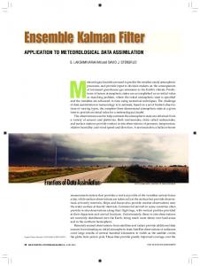
Figure 1: Example of morphing procedure (8) in one dimension. In this example, all variables are nondimensional. The functions u0 (x) and u1 (x) are given on the interval [0, 1]. The intermediate functions uλ are computed by the morphing formula (8), which is seen to interpolate the difference in position as well as the difference in magnitude. The registration mapping T is piecewise linear on the morphing grid in the interval [0, 1] with spacing equal to 0.2. The thin dash-dot lines in the horizontal plane connect the nodes x of the morphing grid with the values of the registration mapping (I + T )(x).
λ=0
λ = 0.25
λ = 0.5
λ = 0.75
λ=1
Figure 2: Morphing of two solutions of a reaction-diffusion equation system used in a wildfire simulation. The states with λ = 0 and λ = 1 are given. The intermediate states are created automatically. The horizontal plane is the earth surface. The vertical axis and the color map are the temperature. The morphing algorithm combines the values as well as the positions.
15
J′
J
B
C
B′
C′
H′
I +T D′ D
A′0
H
A
E
A′
G′
F′
G
F
E′
0
500 1000 Temperature (K)
(a)
1500
−400
Probability density
Probability density
Probability density
Figure 3: Update of the value of I + T at one point by local optimization. The mapping I + T transforms the rectangle BCDEF GJ into the deformed shape B 0 C 0 D0 E 0 F 0 G0 J 0 . The value A0 = (I + T )(A) is to be determined by minimizing the objective function JD (T ) defined by (13), varying only the location of the point A0 , starting from a given initial value A00 . First, the objective function is evaluated at several search points (empty circles) and then, starting from the best location found, it is locally optimized by coordinate descent alternating in the x and y directions, using a standard library function; we have used fminbnd from MATLAB. The mapping I + T is defined by bilinear interpolation in each quadrant (e.g., A0 B 0 C 0 D0 ), and the inverse (I + T )−1 on the quadrant exists if and only if the quadrant is convex (Frey et al., 1978). Thus, A0 is constrained within the quadrilateral B 0 D0 F 0 H 0 (thick dot lines) formed by the midpoints of the sides the deformed rectangle. The search points are constructed by putting several local grid points (here, 2) at equal distance on the segment between the initial position A00 and the midpoint (e.g., A00 B 0 ), and then adding equidistant grid of search points on each of the lines that connect corresponding points, to form a triangle as shown.
−200
0 200 Temperature (K)
(b)
400
−150
−100
−50 0 50 100 Perturbation in X−axis (m)
150
(c)
Figure 4: Probability densities estimated by a Gaussian kernel with bandwidths 37 K, 19 K, and 30 m. Data was collected from the ensemble shown in Fig. 5c. Displayed are typical marginal probability densities at a point near the reaction area of the original temperature (a), the registration residual of temperature (b), and the registration mapping component in the x direction (c). The transformation has vastly improved Gaussian nature of the densities.
16
500
400
400
400
400
300
300
300
300
Y (m)
500
Y (m)
500
Y (m)
Y (m)
500
200
200
200
200
100
100
100
100
0 0
100
200 300 X (m)
400
0 0
500
100
(a)
200 300 X (m)
400
0 0
500
100
(b)
200 300 X (m)
400
0 0
500
100
(c)
200 300 X (m)
400
500
(d)
500
500
400
400
400
400
300
300
300
300
Y (m)
500
Y (m)
500
Y (m)
Y (m)
Figure 5: Data assimilation by the morphing ensemble filter. The forecast ensemble (b) was created by smooth random morphing of the initial temperature profile (a). The analysis ensemble (d) was obtained by the EnKF applied to the transformed state. The data for the EnKF was the morphing transformation of the simulated data (c), and the observation function was the identity mapping. Contours are at 800 K, indicating the location of the fireline. The reaction zone is approximately between the two curves.
200
200
200
200
100
100
100
100
0 0
100
200 300 X (m)
(a)
400
500
0 0
100
200 300 X (m)
400
0 0
500
(b)
100
200 300 X (m)
(c)
400
500
0 0
100
200 300 X (m)
400
500
(d)
Figure 6: After five analysis cycles, the ensemble shows less spread and follows the data reliably. Ensemble members were registered using the initial state, advanced in time without data assimilation (a). The forecast ensemble (b) is closer to the simulated data (c) because of preceding analysis steps that have attracted the ensemble to the truth. The analysis ensemble (d) has a little less spread than the forecast, and the change between the forecast and the analysis is well within the ensemble spread. Contours are at 800 K, indicating the location of the fireline. The reaction zone is approximately between the two curves.
17
(a)
(b)
(c)
Figure 7: The p−value from the Anderson-Darling test of the data from the ensemble after five morphing EnKF analysis cycles shows the ensemble transformed into its registration representation, the registration residual of the temperature (b) and the registration mapping (c), has distribution much closer to Gaussian than the original ensemble (a). The shading at a point indicates where the marginal distribution of the ensemble at that point is highly Gaussian (white) or highly nonGaussian (black).
18