May 24, 2013 - Morphological shape design is interpreted in this paper as a search for new ... In contrast to existing generative procedures, an approach based on a ... with a variety of functions described for the stages of deformation, morphing and offsetting. .... technique is well known with the first detailed survey on.
Morphological Shape Generation through User-Controlled Group Metamorphosis Mathieu Sanchez1 , Oleg Fryazinov1, Turlif Vilbrandt2 , Alexander Pasko1 1 Bournemouth University, UK 2 Uformia AS, Norway
Abstract Morphological shape design is interpreted in this paper as a search for new shapes from a particular application domain represented by a set of selected shape instances. This paper proposes a new foundation for morphological shape design and generation. In contrast to existing generative procedures, an approach based on a user-controlled metamorphosis between functionally based shape models is presented. A formulation of the pairwise metamorphosis is proposed with a variety of functions described for the stages of deformation, morphing and offsetting. This formulation is then extended to the metamorphosis between groups of shapes with user-defined, dynamically correlated and weighted feature elements. A practical system was implemented in the form of plugin to Maya and tested by an industrial designer on a group of representative shapes from a particular domain.
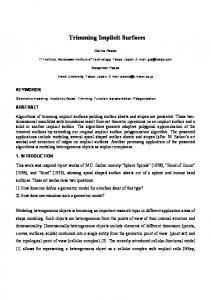
Figure 1: Results of the user-controlled group metamorphosis: the seven initial chairs (blue) with user-defined and weighted features result in the newly generated shapes (pink).
1. Introduction Morphological shape design can be interpreted as a search for new shapes from a particular application domain represented by a set of selected shape instances. While numerous methods exist to perform morphological shape design applied to models, the process is usually controlled automatically, for instance, in genetic algorithms the process is usually controlled by the automatic evaluation of the selection criteria or by the aesthetic evaluation and interactive selection of preferred shape instances by the user. In this paper, we focus on the user control over the process of the shape generation. While we do not propose to exclude using generative procedures as a part of the morphological design process, we aim at providing the user with a richer foundation and feature set Preprint submitted to Computers & Graphics
for morphological design processes than selecting the best instances in the generated population or tuning numerical generative procedure parameters. As Bar-Zeev [1] predicts, real changes in design processes will come ”when we can take two models and say, make A more like B, right here in this part but not that other part. If we solve that, then we can imagine a real open ecosystem for 3D designs that truly credits (and rewards) the creators of original designs while allowing easy mashups of the results.” This approach can be implemented using pairwise metamorphosis between two selected shape instances in a collection of shapes and its extension to the entire collection, parts of the collection or even defined features from the collection. Arbitrary feature identification, continuous dynamic transformations, and resulting model integrity (as required for 3D printing applications) are obvious advantages in comparison to generative procedures. Metamorphosis (or 3D morphing) is a well known technique to transform smoothly one object into another. One of the common applications of metamorphosis is the generation of intermediate shapes in computer animation, however metamorphosis itself can be used as an operation in shape modelling including some applications in architectural design and related areas. There is an established set of techniques to perform a metamorphosis between 3D meshes. Usually these methods are applicable to meshes with the same topology May 24, 2013
or require some knowledge on the topological changes to occur. On the other hand, some of the problems regarding the topological changes can be easily handled by using metamorphosis between objects represented as voxel models, where even the number of the object components are handled in an automatic manner. However most of the methods perform metamorphosis in a fully automatic way and the user control is limited to an entire object’s transformation. Some attempts to introduce more user control were achieved using user defined feature segmentation. Initially this technique was presented for purposes of smooth transitions between two images [2] and then applied for voxel objects in [3]. It allows the user to define pairs of corresponding features in the source object and the target object and interpolate the shape of the source model and the target model by using the information about these features. Features can be defined as a frame with a bounding shape, providing more user control than other existing techniques. However, it heavily relies on the linear interpolation between shapes which does not produce acceptable results in some cases. In this paper we separate feature identification from model data (which typically has to be tightly correlated) and thus generalize the idea of feature-based metamorphosis to allow users to dynamically control shape generation. This approach results in many more possible shape combinations and relationships as well as providing for small local feature based changes or ”tweaks” that maybe desired, but not possible in existing systems (see figure 1). We apply our method to models defined as scalar fields, for example, signed distance fields obtained from polygonal meshes, yet general functionallyrepresented models can also be used as input shapes in our method. This paper presents the following concepts and outcomes:
2. Related Work In computer graphics and shape modelling, morphological shape design was approached through genetic algorithms applied to polygonal models [4], presegmented meshes [5], algebraic surfaces [6], parametric surfaces [7] and procedural implicit models [8]. These methods typically restrict user control to the quality of the model or shape input, manual correlation of the model or shape input, and gross identification of the best resulting shapes, as the evolution process itself is completely automatic. The user also has some loose control over the process through the parameters of the cross-over and mutation. An alternative procedural approach was introduced in [9] for a collection of shapes from an identified complex domain. A probabilistic shape synthesis procedure is applied to a given set of models segmented into compatible components. While metamorphosis has not been directly proposed for the purposes of morphological shape modelling, the technique is well known with the first detailed survey on 3D metamorphosis done in [10]. In that survey at least three approaches were distinguished: based on polygonal meshes, based on scalar fields and conversion methods. Majority of the methods based on polygonal meshes assume that two given shapes have the equivalence of the topology (i.e. the same genus and the same number of components) and have shape matching (i.e. established correspondence between vertices of two shapes) with desirable shape alignment (i.e. correspondence between the origin of the shapes and convex hull for the whole shapes as well as for particular elements). Meshes that have different topology can be used in metamorphosis, however some additional knowledge about topological changes and additional user intervention are required in this case [11]. Metamorphosis algorithms between two models represented by either Function Representation [12] or discrete scalar fields (level sets, voxel models etc) do not require neither topology matching nor shape alignment [13]. However they lack intuitive user control and can be computationally expensive. For example, direct linear interpolation of the defining functions of two given shapes [12, 14] is the simplest metamorphosis on two objects defined in an implicit form and has very simple formulation, but this method can produce poor results for unaligned objects with different topologies. Turk and O’Brien [15] proposed a more sophisticated approach based on the interpolation of surface points (with assigned time coordinates) using radial basis functions in 4D space. This method is more applicable
• Robust foundation for morphological design based on user-controlled metamorphosis; • Generalization of feature-based metamorphosis to using variety of feature shapes, morphing methods and deformations; • Generalization of user-controlled metamorphosis between two shapes to an arbitrary collection of shapes; • Real world application of the presented foundation to morphological design in a particular domain leading to a museum exhibit. 2
to unaligned surfaces with different topologies. However, for the initial implicit surfaces this method requires time-consuming surface sampling and interpolation steps. Recently another method of shape metamorphosis called space-time blending was introduced in [16]. This method does not require shape alignment, however the user can only affect the entire metamorphosis process rather than specific features of the shape and it can be difficult to correctly define several complex parameters. More user control can be achieved by restricting the class of objects. Thus, in [17] some control over the metamorphosis of skeletal soft object was achieved by cellular matching or hierarchical matching and the metamorphosis was performed by interpolating the positions of the skeletons and the field intensities. The main drawback of this method is the requirement of skeleton matching for two objects which is similar to the shape matching problem defined for polygonal models. Later in [18] this limitation was partially lifted, however the matching between the structure of two objects was still the issue. Group metamorphosis was addressed for limited groups of objects with simple weighting schemes such as barycentric coordinates for three objects [19] and the bilinear interpolation for four objects [20].
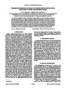
Figure 2: Matching features with different types of geometry for feature elements: for legs cylinders are used, for spine a prism-like polytope.
point set belonging to the surface of feature element; 2. The feature element encloses the spatial area of the object we want to deform; 3. Each feature element Ea of the object A corresponds to the feature element Eb of the object B with the requirement of bijective mapping T that maps any point pA ∈ Ea to the point pB ∈ Eb and inverse mapping T I that maps the point pB back to pA . 4. The geometry of the shape of the element i can be arbitrary, without any limitations on genus and number of disjointed components as long as the properties above are held;
3. User-controlled pairwise metamorphosis Let us consider the source object A and the target object B represented by the real-valued functions fa (x, y, z) and fb (x, y, z). While there are no restrictions on these functions, it is preferable that these functions have distance properties. Thus, for any two points p1 and p2 whose Euclidean distance to a given object are equal to d(p1 ) and d(p2 ) respectively, if d(p1 ) > d(p2 ) then f (p1 ) > f (p2 ). One of the possible representations providing these properties is a signed distance field obtained for the object represented by a polygonal mesh [21]. The considered metamorphosis problem is to obtain an intermediate object between the source and the target ones under the user’s guidance on the corresponding parts. To define parts of the objects and their correspondence in the metamorphosis process, we adopt the notion of the feature element defined in the feature-based metamorphosis [3] to further extend it. Let us describe the feature element as follows:
The features can overlap and do not need to be accurately placed thanks to a smooth weighting function described in subsection 3.3. An example of corresponding features defined for two objects is shown on figure 2. Thus, the user defines n feature elements on the source object and corresponding n elements on the target object. For each feature element i we define the weighting function wi (di (x, y, z)) depending on the distance to the feature element’s shape obtained with the distance function. The morphing function fm ( fa , fb , t) is chosen such that fm ( fa , fb , 0) = fa and fm ( fa , fb , 1) = fb ; here t is a parameter to define the evolution of the morphing object, t ∈ [0, 1]. Apart from the morphing function, we introduce a feature-based offsetting function oi (t) defined for each feature separately allowing to control the behaviour of parts of the object enclosed by features.
1. The shape of the element i is represented by a realvalued function di (x, y, z) with the distance property defined above, di (x, y, z) = 0 represents the 3
x to x 0a
x to x 0b
x to x na
can be used as the morphing functions. Here we describe the morphing functions fm that provide simple formulation and good performance, however without limiting ourselves to these functions. The simplest morphing function is a linear interpolation between fa and fb :
x to x nb
fm (t) = fa · (1 − t) + fb · t morph
This function is the easiest to evaluate, however in case of thin features the control over the intermediate shapes becomes very hard. In a more general way, linear morphing does not provide intermediate shapes that resemble the source or target shapes. Furthermore, disconnected components often appear making intermediate shape unsuitable for fabrication and unrealistic. Another morphing function providing more user control is space-time blending presented in [16]. Overall, this method provides better results compared to linear metamorphosis and provides better user control over the result. In case the user wants to make the morphing process and deformation process more independent, a nonlinear function for time can be used. In this case in equations for morphing, for example in equation 2, instead of the parameter t we use function u(t). Examples of such a functions are u(t) = t in the simple linear case, u(t) = tn , n ∈ N if we want to accelerate the morphing process towards the end of transition from A to B or 1 u(t) = t n , n ∈ N if we want to accelerate the morphing process at the beginning of this transition.
morph
weighted average
Figure 3: The process of the pairwise metamorphosis with userdefined and weighted features.
This is necessary when the features (e.g. chair legs) bound thin volumes which are very different in each object. The morphing then fails to produce any volume even locally. The general user-controlled metamorphosis function can be formalized as follows:
F M (x, t) =
n P
i=1
� � wi (di (x)) fm ( fa (xia ), fb (xib ), t) + oi (x) n P
(2)
wi (di (x))
i=1
(1) Here xia denotes the point in the object A and xib denotes the point in the object B corresponding to the point x = (x, y, z) in the frame i by using forward and inverse transformation mentioned above. Thus the process of obtaining the shape from the source and the target object can be seen as application of the following scalar field operations over these objects: weighted average of morphed objects after transformations (or space mappings in more general case) induced by feature elements and additional operations such as offsetting (see figure 3). The ”x to xia ” and ”x to xib ” to represent the transformation of the object using the feature i for both objects. Below we discuss several possible functions for the morphing, mapping, offsetting and weighting in this formulation.
3.2. Space mappings Mapping T I allowing to obtain the point xia in the feature for the source object A and the mapping T allowing to obtain the point xib for the target object B corresponding to the point x = (x, y, z) in the frame i is a bijective mapping. In applications to shape modelling with real functions, we can distinguish the following mappings: affine mapping, twist, taper, bending, and their combinations. All the mentioned mappings have simple formulations for both forward and inverse cases. For the metamorphosis applications we assume that there exists an interpolation between the values for the mapping parameters. These parameters are a transformation matrix in affine mapping, an angle of twisting, a scale factor for tapering, and others. In general, considering the mapping T : p0 = T (p) with its inverse function T I : p = T (p0 ) with the given time-depending parameter u(t), so that T = T (p, u) and T I = T I (p, u) where u(0) = ua and u(1) = ub are values of the specific
3.1. Morphing functions Most of the functions that are used for generic metamorphosis on two shapes defined in the implicit form 4
(a)
(b)
Figure 5: Deformation part of the metamorphosis: (a) the original chairs A and B, (b) chair A under deformation of B (left) and chair B under deformation of A (right) Figure 4: Morphing and deformation parameters can be independent of each other, and dependent on space. Here parameters are featurebased.
This function, however, is not fully controllable because of difficulties of tweaking the behaviour with the epsilon value and the exponent and a large drop at the boundaries of the features, making the feature shapes visible during the animation. Instead, we use the technique similar to the material interpolation in heterogeneous modelling [23] to support features that can overlap at the transition stage: max(0,di ) max(di ) >0 n i X max(0, d ) j j=1 n Y (5) wi = dj j=1; j,i otherwise n n X Y dk j=1 k=1;k, j
parameter in the source and destination objects, we can obtain the point in the source object as follows: xa = T I (x, u(t)) xb = T (x, u(1 − t))
(3)
The simplest case of the mapping function is the affine transformation. In this case, the forward mapping is defined by the transformation matrix, the inverse mapping is defined by the inverse of the transformation matrix and we interpolate between the transformation matrices as, for example, it was shown in [22]. Alternatively, instead of matrices, quaternions and spherical linear interpolation can be used. As for morphing, instead of the linear time parameter t, more general function can be used to accelerate the deformation process towards the model A or the model B. Both morphing and deformation parameters can be entirely independent, and defined using a trivariate function. An easy solution to provide control to the user is to set the parameters per feature. Figure 4 shows the use of this technique between the armadillo model and the Buddha model from the Stanford repository. The morphing parameter is set per feature to take elements of the Armadillo model and elements of the Buddha model and combining them together. Some parts are blends of the feature pairs.
The transformation in [3] was a simple affine transformation, which moved both objects so that their features would match the interpolated feature. If this process is made for all the features, and then a weighted average of the field is applied, where the weight is a function of space, a simple deformation can be achieved (as seen in Figure 5). 3.4. Offsets Thin-features tend to disappear, or disconnect from each other. While the previous operations greatly help to resolve this issue, additional operations may be needed. A general offset can be applied to the final field to reconnect the disconnected components. However, it blurs out the details where the offset is not needed. A better approach would be to define a new scalar field to feed the offset value. This would allow to reconnect the disconnected components exactly where it is needed. Such field is not trivial to define, especially for designers. An intermediate solution is to define the offset per feature. The offset can simply be defined as follows: oi (x) = di (x) + d (6)
3.3. Weighting functions In the metamorphosis defined with features it is important that the shape deformation depends on the behaviour of the shape of the feature and the closer the point in the space to the feature the more this influence should be. In the original paper on feature-based metamorphosis [3] the square inverse of the feature distance is used as the feature weight: w(d) =
1 (d + ε)2
(4) 5
Simple offsetting operations only work seamlessly if the field has distance properties. Otherwise, more complicated procedures have to be used. 4. User-controlled group metamorphosis In the previous section we discussed how the shape can be designed by using the user-controlled metamorphosis between two objects. Although, this pairwise metamorphosis can be applied in a step-by-step manner to a group of objects, a more challenging issue is to generalize the proposed formulation to apply directly to a group of objects to design a new shape. Surprisingly enough, the increase of the number of objects requires only minor changes to the initial formulation given in the equation 1. Given k objects where j-th object, 1 ≤ j ≤ k, is defined by a real-valued function f j (x, y, z) with the morphing function fm ( f1 , f2 , ..., fk ) and n feature elements defined for each object such that the signed distance function for the feature i of the object j is d j,i , the user-controlled group metamorphosis function becomes:
F Mk (x, t) =
n P
i=1
�
wi (di (x)) fm ( f1 (xi1 ), ..., fn (xin )) + oi (x) n P
Figure 6: Maya plug-in interface for the user-controlled metamorphosis.
be able to interpolate between several different transformations. Even in the case of affine transformations this becomes not an easy task, as the weighted average is straightforward for translations and scales, but it is more complicated for orientations. The SLERP on quaternions and the matrix rotation interpolation do not extend well to the weighted average of k elements. Some methods exists, for example, presented in [24], however there is a possibility of getting invalid results from the design point of view. Input: P: Position k: Number of objects f j : jth object’s field Ei, j : Original feature i of object j Output: Field value at P ret ← 0 ; denom ← 0 ; foreach Feature i do Ei0 ← Interpolated feature i ; R ← relative position of P in regards to feature Ei0 ; accum f ield ← 0 ; foreach Object j do Q ← absolute position of R in regards to Ei, j ; accumv ← f j (Q) · vi ; accum f ield ← accum f ield + accumv ; end di ← distance from P to feature Ei ; wi ← w(di ) ; ret ← ret + (accum f ield + oi ) · wi ; denom ← denom + wi ; end ret ; return denom Algorithm 1: Group metamorphosis with affine transformations
�
wi (di (x))
i=1
(7) Unlike the pairwise metamorphosis described in the previous section, the variety of applicable functions is more limited because most of the methods do not extend to more than two arguments. Thus, space-time blending can not be extended to several input models and therefore the only suitable function for morphing involves the linear interpolation as follows:
F Mk (x, t) =
n P
wi (di (x))
i=1
k P
j=1 n P
! f j (x j,i)vi + oi (x)
(8)
wi (di (x))
i=1
where vi defines the weight or the influence of the feature element i in the group metamorphosis process with n P vi = 1. i=1
The available transformation functions are also more limited. As we discussed above, we use the forward and inverse transformations to map the point from the original feature elements to the intermediate feature element and back. In the case of multiple objects we have to
Despite these limitations the user still has control over the process as offsetting and weighting functions 6
(a) (a)
(b)
Figure 8: Applications and results: a) The three chairs from Figure 1 printed using an Envision TEC Ultra 3d printer, b) Sketch of an exhibit in a contemporary art museum. (b)
tion for metamorphosis with different values of the parameter t. As we are working with the metamorphosis shape defined in the implicit form, we use isosurface polygonization to generate the mesh for a given t value. The resulting intermediate shapes can be imported back to Maya to analyse the results and adjust feature elements or parameters of the metamorphosis. In the future, a component for visualization many resulting models and interacting with their related feature parameters in mass is planned. The simple formulation of our method allows us to generate intermediate shapes quickly. The time to generate the sequence in figure 7 for low quality visualization was 15 seconds. We used the group metamorphosis in figure 1 to generate three chairs (in red) from a set of seven chairs (in blue). The designer provides the seven chairs and defines their corresponding features. While any features and correlations can be defined (and redefined), here the designer used four features for the legs, two for the arm rests, one for the seat and one for the back. Using this data a matrix k×n values where each element of the matrix provides a single value for the deformation and morphing parameter per feature and per model. While internally the sum of the weights for a feature must equate to one, we allow the designer to use arbitrary weighted values and normalize internally. Additionally, to ensure the objects are printable, we added feature based offsets provided per feature. Some examples have been fabricated using an Envision TEC Ultra 3D printer (see figure 8a). User control allows to obtain far better results than automatic metamorphosis (see figure 7) even where the user can define feature elements. In the example of the models with thin feature elements, linear metamorphosis does not produce sensible results while using space-time blending leads to some features disappearing and growing in unwanted places. Feature-based metamorphosis [3] produces better results as a designer can choose the best values for each feature set and prevent,
(c)
(d) Figure 7: Comparison of different metamorphosis methods for objects represented with signed distance fields. a) linear metamorphosis, b) space-time blending, c) feature-based volume metamorphosis, d) our method of the pairwise metamorphosis with space-time blending and additional local offsets.
depend on the feature distance field and therefore we can use the same formulation as presented in the previous section. In the algorithm 1 we show how the group metamorphosis can be implemented in the case of affine transformations applied to feature elements. 5. Implementation and Results We have implemented our approach as a Maya plugin and an additional stand-alone application both written in C++. In the Maya plug-in (see figure 6) the user defines a source, a target mesh and feature elements. To define the features, the user places bounding boxes within the source and the target models for each feature element using typical interactive modelling procedures. The user defines the corresponding relationship between features and sets up the parameters for metamorphosis. The feature relationships and parameters can be easily refined as any point at any stage of the process. This information is then exported and used by the stand-alone application which generates intermediate shape defini7
for example, thin or small features from vanishing in various stages of the metamorphosis. It should be noted that the impetus for this research has been an ongoing collaboration of the authors with a well-known designer to develop a practical and usable system for generalized morphological design. Of particular interest was applying this method to morph between famous and well known chair designs. The current goal is to ”mate” classic seating forms in a quest to find the most beautiful, most perfect chair ”species”. Figure 8b shows a sketch of the proposed exhibit in a contemporary art museum.
has been developed by Jan Habraken at FormNation (http://www.formnation.com/) in New York City. References [1] A. Bar-Zeev, Death to poly, in: RealityPrime, 2012, http //www.realityprime.com/blog/2012/11/death-to-poly/. [2] T. Beier, S. Neely, Feature-based image metamorphosis, SIGGRAPH Comput. Graph. 26 (2) (1992) 35–42. [3] A. Lerios, C. D. Garfinkle, M. Levoy, Feature-based volume metamorphosis, in: SIGGRAPH ’95, ACM, 1995, pp. 449–456. [4] K. Sims, Evolving 3d morphology and behavior by competition, Artif. Life 1 (4) (1994) 353–372. [5] K. Xu, H. Zhang, D. Cohen-Or, B. Chen, Fit and diverse: set evolution for inspiring 3d shape galleries, ACM Trans. Graph. 31 (4) (2012) 57:1–57:10. [6] E. J. Bedwell, D. S. Ebert, Artificial evolution of algebraic surfaces, in: Implicit Surfaces ’99, 1999, pp. 81–88. [7] A. Lamas, R. Duro, Automatic 3d morphological design through evolution, in: IDAACS 2005. IEEE, pp. 564–569. [8] S. Silva, P.-A. Fayolle, J. Vincent, G. Pauron, C. Rosenberger, C. Toinard, Evolutionary computation approaches for shape modelling and fitting, in: Proceedings of the 12th Portuguese conference on Progress in Artificial Intelligence, EPIA’05, Springer-Verlag, 2005, pp. 144–155. [9] E. Kalogerakis, S. Chaudhuri, D. Koller, V. Koltun, A probabilistic model for component-based shape synthesis, ACM Trans. Graph. 31 (4) (2012) 55:1–55:11. [10] F. Lazarus, A. Verroust, Three-dimensional metamorphosis: a survey, The Visual Computer 14 (8/9) (1998) 373–389. [11] D. DeCarlo, J. Gallier, Topological evolution of surfaces, in: Proceedings of Graphics interface, 1996, pp. 194–203. [12] A. Pasko, V. Adzhiev, A. Sourin, V. Savchenko, Function representation in geometric modeling: Concepts, implementation and applications, The Visual Computer (11) (1995) 429–446. [13] J. F. Hughes, Scheduled fourier volume morphing, SIGGRAPH Comput. Graph. 26 (1992) 43–46. [14] D. Cohen-Or, A. Solomovic, D. Levin, Three-dimensional distance field metamorphosis, ACM TOG 17 (1998) 116–141. [15] G. Turk, J. F. O’Brien, Shape transformation using variational implicit functions, in: SIGGRAPH ’99, 1999, pp. 335–342. [16] G. Pasko, A. Pasko, T. Kunii, Space-time blending, Computer Animation and Virtual Worlds 15 (2) (2004) 109–121. [17] B. Wyvill, Metamorphosis of implicit surfaces, in: Modeling, Visualizing and Animating with Implicit Surfaces, 1993. [18] E. Galin, A. Leclercq, S. Akkouche, Morphing the blobtree, Computer Graphics Forum 19 (4) (2000) 257–270. [19] V. Adzhiev, P. Comninos, M. Kazakov, A. Pasko, Functionally based augmented sculpting, Computer Animation and Virtual Worlds 16 (1) (2005) 25–39. [20] E. Fausett, A. Pasko, V. Adzhiev, Space-time and higher dimensional modeling for animation, in: Proceedings of the Computer Animation, IEEE Computer Society, 2000, pp. 156–165. [21] B. A. Payne, A. W. Toga, Distance field manipulation of surface models, IEEE Comput. Graph. Appl. 12 (1992) 65–71. [22] K. Shoemake, T. Duff, Matrix animation and polar decomposition, in: Proceedings of Graphics interface, 1992, pp. 258–264. [23] A. Biswas, V. Shapiro, I. Tsukanov, Heterogeneous material modeling with distance fields, Comput. Aided Geom. Des. 21 (3) (2004) 215–242. [24] M. Moakher, Means and averaging in the group of rotations, SIAM J. Matrix Anal. Appl. 24 (1) (2002) 1–16.
6. Conclusions and Discussion In this research we have considered the larger foundational issues behind morphological shape design. The proposed method has many advantages as a foundation for morphological shape design, including the integrity of resulting models and the arbitrary identification of any number of features across dynamic model sets. However, several issues still require continued research and development. The system as it is currently implemented can require setting many different parameters to achieve a desired result, which can be confusing for some designers. Despite this ”black box” approach, the method we present is basically a node based design similar to the general highly-parametrized computeraided design systems. While we do think more control is better than less in design processes, we also believe in simplicity and future work aims to replace valueparameter pairs by an appropriate function or variety of functions allowing user to use the one most suitable for their purposes. In this context, it is also important to point out, as previously discussed in the description of user-controlled group metamorphosis, that user control becomes constrained by the limited number of methods to morph and transform between a large number of input shapes. A more detailed investigation is needed in this area to find ways to lift this limitation. Other interesting directions in the future include incorporating the proposed approach into a practical computer-aided design system and combining it with generative procedural approaches. Acknowledgements This work was partially sponsored by the EU Interreg IVA project 5-023-FR SHIVA. Also this research and development was the product of collaboration around an ongoing project, Chairgenics, which originated and 8