A new switch-level fault simulation method for MOS circuits is presented that combines compiled switch-levelsimulation techniques andfunctional fault modeling ...
VLSI DESIGN 1996. Vol. 4. No. 3. pp. 217-229 Reprints available directly from the publisher Photocopying permitted by license only
(C) 1996
OPA (Overseas Publishers Association) Amsterdam B.V. Published in The Netherlands under license by Gordon and Breach Science Publishers SA Priflted in Malaysia
Switch-level Differential Fault Simulation of MOS VLSI Circuits EVSTRATIOS VANDRIS a’* and GERALD SOBELMANb’* aAT&T Bell Laboratories, 600 Mountain Avenue, Murray Hill, NJ 07974; bElectrical Engineering Department, Minneapolis, MN 55455
University
of Minnesota,
A new switch-level fault simulation method for MOS circuits is presented that combines compiled switch-level simulation techniques and functional fault modeling of transistor faults with the new fault simulation algorithm of differential fault simulation. The fault simulator models both node stuck-at-0, stuck-at-1 faults and transistor stuck-on, stuck-open faults. Prior to simulation, the switch-level circuit components are compiled into functional models. The effect of transistor faults on the function of the circuit components is modeled by functional fault models that execute very fast during simulation. Every compiled circuit component is assigned a dominance attribute, which abstracts relative strength information in the circuit. Dominance is used during simulation to resolve the X-state due to fighting pull-up and pull-down transistor paths and also to deduce transistor fault detectability and fault equivalencies prior to simulation. The differential fault simulation algorithm developed for gate-level circuits is adapted for use at the switch-level. Differential fault simulation provides excellent performance with minimum memory requirements, although it incurs a higher overhead at the switch-level than at the gate-level due to the dynamic memory properties of MOS circuits. Kevwords: Fault Modeling, Fault Simulation, Switch-level Simulation
1. INTRODUCTION
the good circuit. Therefore the fault simulator can determine the fault coverage of the test sequence, which is defined as the ratio of the number of faults detected to the total number simulated. Fault simulation provides useful feedback as to what areas of the chip are not being tested by the vector set. Additional test vectors can then be written for the untested logic to increase fault coverage. Also, inherently untestable areas of the chip can be identified and the logic redesigned to increase testability.
Fault simulation is used to determine the effectiveness of a sequence of test vectors in detecting manufacturing faults in integrated circuits. A fault simulator generates all possible faults for the circuit and then simulates the good circuit and all the faulty circuits for a set of test patterns applied to the inputs. A fault is considered detected if the particular faulty circuit gives a different logic value at an output than *Phone: (908) 582-3205 *Phone: (612) 625-8041
217
218
E. VANDRIS and G. SOBELMAN
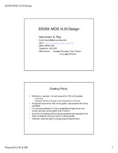
Fault simulators based on a gate level model can model only a limited class of faults that are possible in MOS circuits, such as gate inputs and outputs stuck-at-0 and stuck-at-1 faults. However, the majority of MOS manufacturing faults are due to short- or open-circuited transistors and wire shorts or opens [1], [2]. These faults can often change even a simple MOS gate into a sequential circuit or change the gate function in such a way that it cannot be modeled as an input/output s-a-0/1 fault [3], [4]. Furthermore, MOS circuits exhibit properties such as bidirectionality of signal flow, dynamic charge storage, charge sharing and ratioed circuits that cannot be modeled at the gate level. For this reason, fault simulation of MOS circuits should be performed at the transistor switch-level, where transistor stuck-on and stuckopen faults and wire shorts and opens can be modeled. For VLSI circuits, thousands of faults have to be simulated during fault simulation and straightforward serial fault simulation (in which the good circuit and each faulty circuit are simulated separately) would be computationally very expensive. Various techniques have been devised to reduce the amount of computation necessary by exploiting inherent parallelism and concurrency in fault simulation. In the context of fault simulation, parallelism implies the simultaneous simulation of many identical circuits corresponding to different faults or patterns. Concurrency, on the other hand, implies the simultaneous simulation of only those identical circuits whose response is different than the reference circuit for different faults or patterns. There are 3 different dimensions along which parallelism and concurrency can be exploited for the acceleration of fault simulation: faults, data patterns and circuit components. This is shown in Fig. as a 3-dimensional diagram with faults on the x-axis, data patterns on the y-axis and circuit components on the z-axis. The techniques of parallel fault, concurrent fault and parallel value list simulation exploit parallelism along the fault-axis, while the techniques of parallel pattern and concurrent pattern simulation exploit parallelism along the data pattern-axis. Circuit parallelism can be exploited by assigning indepen-
Circuit Components Circuit Parallelism
Mul ti prc
I
siIng
Faul ts
/, Data
/!Hi! .Parallel Fault sire
Concurrent
3.2" FaUltparalllelListSim
patter
Value
4. Single Fault Propagation
Parallel Pattern sire (PPSFP)
5. Differential Fault sire
2. Concurrent Pattern sire
FIGURE
Parallelism and Concurrency in Fault Simulation
dent circuit partitions on the processing units of a
multiprocessor. The issues involved in fault simulation can be examined by considering the evaluation matrix defined by the x-y plane of Fig. [23]. As shown in Fig. 2, the rows correspond to the faults of the circuit F1, Fn (plus one for the good circuit, denoted as G F2 or F0) while the columns correspond to the data input Dm. The objective of patterns applied D 1, D2, D3 values at each node evaluate the is fault simulation to in the circuit for each fault and data pattern, i.e. to obtain all the entries in this matrix. Fault parallelism is exploited in parallel fault simulation [5] which evaluates the matrix column by column, where each column corresponds to a different data pattern. It uses the computer’s wordlength to simulate many faults in parallel with each bit in the computer word representing the response of the particular faulty circuit. The simulation of the circuit is
DJ
Dm
Gt G2 FI FI,1 F2 F2,1
Gj FI,j
Gm
Fi
FI,j
DI D2 D3 G
Fz,j
FIGURE 2 The Evaluation Matrix
SWITCH LEVEL FAULT SIMULATION
performed by Boolean operations (AND, OR, NOT) on computer words, corresponding to Boolean gates in the circuit. There are, however, a great number of wasted simulations performed, since the potential effect of each fault is calculated for all gates, even though most gates could not be possibly affected by most faults (fault masking). Data parallelism can be exploited by simulating many data patterns in parallel (as opposed to many faults in parallel as in parallel fault simulation) using each bit of the machine wordlength to represent a value in the good or faulty circuit for each data pat32 bits, then a goodtern. If the wordlength is W circuit simulation is first performed in parallel for 32 patterns using AND, OR and NOT bit-wise operations, corresponding to Boolean gates in the circuit. Then, for each fault being considered, the fault vectors of 32 patterns are propagated forward, beginning at the point of the fault and continuing until fault values are no longer different from the good-circuit values. This technique, called parallel pattern single
fault propagation (PPSFP) [15], 16] evaluates the matrix row by row, each row corresponding to a different fault. In addition, it checks whether any row (the faulty values) is identical to the first row (the good values) and drops such a vector from further simulation. The parallel pattern evaluation technique has been adapted to the switch-level for good-circuit simulation only [17]. Parallel pattern simulation requires that W separate input test sequences be avail32. The able, where W is the wordlength, e.g. W state of the circuit should not depend on any of the previous data inputs in the parallel vector, since all 32 patterns in the vector are simulated in parallel. Therefore, PPSFP applications are mainly limited to combinational circuits. By using a vector processor [18], [19], or a multiprocessor [20], [21], [22] the rows or the columns of the matrix can be evaluated in parallel, leading to parallel pattern parallel fault simulation. The evaluation matrix, however, is inherently sparse, not in the sense of having a few non-zero entries but in the sense that many of the entries are identical to the first reference entry. This is because each faulty circuit typically differs only slightly from the good circuit,
219
since the fault affects only a small portion of the circuit. This sparsity amounts to unnecessary storage and circuit evaluations. The parallelism of vector processors or multiprocessors may make that overhead tolerable but on a uniprocessor is very important to avoid that overhead. Concurrent fault simulation [6] exploits the sparsity of the evaluation matrix to reduce the execution time of fault simulation on a uniprocessor. The good circuit is simulated in its entirety but only selective portions of the faulty circuit that are affected by a fault are simulated concurrently with the good circuit. Concurrent fault simulation evaluates the matrix one column at a time, using a linked list to represent only entries which are different from the first reference entry and dropping further simulation of entries identical to the reference (i.e., dropping from further propagation to other circuit components). Event-driven concurrent fault simulation has been the most prevalent fault simulation technique due to its simulation efficiency and its ability to handle easily different fault models, sequential circuits and functional models [7]. However, the main disadvantage of concurrent fault simulation is the large memory requirement, since the state of the good circuit and all the faulty circuits must be maintained simultaneously. There is also a performance overhead in traversing the fault lists to trace fault effects and removing or inserting faults from the lists. Another technique, the parallel value list, [13] combines the features of parallel and concurrent fault simulation [14]. Faults are grouped together in a given parallel value word, chosen on the basis of their proximity with one another. If the faults are close together in the circuit and there is no activity in that area of the circuit for the particular pattern simulated, the fault word is quickly dropped from forward propagation. Only active fault groups are propagated as in concurrent fault simulation. Although combining the advantages of the two techniques, it also suffers from the disadvantages mentioned above. A similar method, single fault propagation, also evaluates the matrix by columns, but only one entry at a time. In other words, each faulty machine is simulated separately for a given data pattern, with only
E. VANDRIS and G. SOBELMAN
220
the differences between the good and faulty machines simulated. It does not incur the high memory overhead of concurrent fault simulation but has the overhead of restoring the good circuit state before each faulty machine evaluation, because the good and faulty machines are not simulated simultaneously. Instead of exploiting similarities of the faulty machines with the good reference machine as in concurrent fault simulation or single fault propagation, one could exploit the similarities between successive faulty machines F and Fi+ 1. In other words, one would evaluate the matrix by columns, one entry at a time, in the order Gj, F l,j, F2, Fn, for each vector Dj. This technique is called differential fault simulation [23]. In differential fault simulation, an event is defined as a difference between successive faulty machines rather than a difference between the good and faulty machine or a difference in the same machine under successive patterns. It does not require the overhead of restoring the good machine state before each faulty machine simulation as does single fault propagation. Moreover, it requires much less memory than concurrent fault simulation, because it does not keep copies of the good and all faulty machines running concurrently. Finally it can handle both combinational and sequential circuits [24]. We can summarize the various fault simulation techniques according to the order of evaluation of the entries in the matrix of Fig. 2 as follows:
Technique 1. Single Fault
Propagation
2. Differential Fault Simulation 3. Concurrent Fault Simulation
5. Parallel Fault Simulation
Evaluation Method
By columns, one faulty machine (entry) at a time, evaluated only if different from the good machine (first entry in each column) By columns, one entry at a time, evaluated only if different from the previous faulty machine By columns, all column entries concurrently evaluated only if different from the good machine (first column entry) By columns, all column entries in parallel
6. Parallel Pattern By rows, all row entries in parallel, evaluated only if faulty Single Fault machine row is different from Propagation the good machine row (PPSFP) 7. Parallel Pattern By rows or columns, all row/ Parallel Fault column entries in parallel and all rows/columns in parallel (on a vector processor or multiprocessor)
Concurrent fault simulation, originally developed for gate-level circuits, has been extended to the transistor switch-level in the simulators FMOSSIM [8-9], DECSIM [10-11], MOZART [12] and FCOSMOS [34]. However, switch-level simulation is generally slower than gate-level simulation and the number of faults at the transistor switch-level is much higher than the gate-level. This large increase in the number of faults coupled with the low speed of simulation at the switch-level has prevented switch-level fault simulation from becoming practical for large circuits. Also, due to the nature of switch-level circuits, the implementation of concurrent fault simulation at the switch-level has been much more complex with additional memory and performance overhead. We have developed a new switch-level fault simulator that uses differential fault simulation, to achieve minimum memory requirements and performance overhead, both of which are essential to performing practical fault simulation at the switch-level due to the large number of switch-level faults. It also uses high speed compiled switch-level simulation that approaches-the speed of gate-level simulation. The remainder of this paper describes the design and performance of our switch-level fault simulator. In section 2, the switch-level simulation techniques used in our simulator are discussed and compared with other switch-level simulators. In section 3, a new functional fault modeling technique that models the effect of transistor faults on compiled circuit components is presented. In section 4, the calculation of the transistor group dominance, which is a property used to resolve the X-state during simulation and also to identify transistor faults undetectable by logic monitoring, is presented. In section 5, our implemen-
SWITCH LEVEL FAULT SIMULATION
tation of differential fault simulation at the switchlevel is described. In section 6, simulation results for typical circuits are presented to evaluate the fault simulator’s performance. Finally, our conclusions are presented in section 7.
2. SWITCH-LEVEL FAULT SIMULATION Switch-level simulators [25] represent transistor structures explicitly, modeling transistors as bidirectional resistive switches, controlled by the state of their gate terminal. Transistor conductance is modeled by a set of discrete strengths and node capacitance is modeled by a set of discrete sizes. A path of conducting transistors takes on the strength of its weakest transistor. A circuit node, affected by different signals through conducting transistor paths, takes the logic value (0 or 1) of the path with maximum strength. When transistor paths of equal strength but opposite logic values drive a node, the node is set to X, to represent an unknown logic value. Two types of switch-level fault simulators have been developed: interpreted and compiled. Interpreted simulators evaluate the circuit response at run time while compiled simulators extract function information from the circuit at compile-time and make use of this information to achieve faster simulation at run-time. Interpreted fault simulators such as FMOSSIM [9] have suffered from low speed, because the interpretive switch-level algorithm is slow. In addition, the frequent occurrence of the X-state due to a transistor fault causes these transistor faults to be declared as being only potentially detected (soft-detects) and in a corresponding uncertainty in the fault coverage. These faults can potentially be detected, because the intermediate voltage levels they create may or may not be sufficient to switch further stages and drive a primary output to the opposite logic value of the good circuit. Additionally, many transistor stuck-on faults are undetectable by logic monitoring because even when they are sensitized a stronger opposing path overrides their fault effect [31]. Other fault simulators have tried to remedy
221
these problems by using a multivalued algebra with more than 3 logic states [32], [33]. However, this made the simulation algorithm more complicated and sacrificed simulation speed. Compiled switch-level simulators improve simulation speed by using symbolic analysis to preprocess the network into a functionally equivalent Boolean representation for simulation [26-29]. For example, the compiled simulator COSMOS [30] generates compiled code that computes the response by executing the extracted sequence of Boolean operations. Compiled simulators achieve higher simulation speed than interpreted simulators but incur a substantial time overhead in generating the compiled network description. FCOSMOS [34], the fault simulator based on COSMOS, models only stuck-at faults on a subcircuit’s inputs and outputs, in order to avoid the overhead of symbolically analyzing and recompiling subcircuits containing transistor fault effects. Moreover, in FCOSMOS the X-state problem due to transistor faults has not been alleviated. Our fault simulator is based on Soisim, a switchlevel simulator developed at AT&T Bell Laboratories [35], [36]. Soisim combines the advantages of compiled and interpreted switch-level simulation techniques to achieve high simulation speed at the switch-level. Before simulation, a static partitioning of the circuit into channel- connected components is performed (i.e., into groups of transistors connected by their sources and drains only). During compilation, each channel-connected component of a circuit is matched against a library of primitives, such as static and dynamic CMOS gates, latches, multiplexers, etc. A functional model in C code is substituted for each structure prior to simulation. Typically, 85% of the channel- connected components of a circuit are successfully matched and modeled during compilation. Any transistor groups that are left unmatched are simulated at the switch-level using partially ordered strengths [35] and a simulation algorithm similar to MOSSIM II [25]. Compiled transistor groups are simulated by executing the C code of the group functional model, which results in high simulation speed. The simulator is event-driven, with events scheduled
222
E. VANDRIS and G. SOBELMAN
at the transistor-group level. Soisim can handle arbitrary digital MOS circuits and it is much faster than interpreted simulators due to its compilation capability. However, unlike COSMOS, it does not attempt to compile circuit components with complex behavior. This avoids excessively long compilation times. Our fault simulator models both node stuck-at faults and transistor stuck-on and stuck-open faults. To achieve high simulation speed, functional fault modeling is used to model the effect of transistor faults on compiled circuit components. The dominance property of the circuit components is used during simulation to resolve the X-state due to transistor stuck-on faults.
dominance [39] to abstract relative strength information in the compiled transistor groups. A group is said to be n-dominant if its pull-down network overpowers the pull-up network when both are on. Similarly, the group is p-dominant if the pull-up network overpowers the pull-down network. Finally the group is said to have no dominance if neither one overpowers the other. The output node out is then evaluated according to the following table:
pd on
pu off
off
on
off
off
out 0 /* s-open fault */
out-
0 (n-dom)
3. FUNCTIONAL FAULT MODELING
on
on
(p-dom)
/*s-on fault */
X (no dom) The fault simulator can model node stuck-at faults on the inputs and outputs of transistor groups (channelconnected components) of the circuit. As the simulator identifies logic gates from transistor groups during the compilation phase, this corresponds to a gatelevel fault model, where only faults on inputs and outputs of logic gates are modeled. Transistor stuck-on and stuck-open faults can also be modeled inside transistor groups. The functional model of a transistor group in the fault simulator models the behavior of the good circuit and the faulty circuit in the presence of any fault in that group. Depending on the particular fault to be simulated, the functional model selects the appropriate faulty behavior of the group. This method of fault modeling preserves the speed advantage of compiled simulation and results in high-speed fault simulation. By using compiled fault models, we avoid the overhead of symbolically analyzing all faulty groups to extract their function under the presence of different faults. A general functional model for restoring and nonrestoring CMOS logic is used [37], [38] that allows functional fault modeling of transistor faults. Restoring logic is modeled as consisting of a pull-up network of p-type transistors and a pull-down network of n-type transistors. The model uses the concept of
where pd and pu are the pull-down and pull-up transmission functions, respectively, and out- is the previous value of the output node. The transmission function gives the conditions under which one or more paths form across the network terminals and it has value when the transistor network is on and value 0 when it is off. The compiler extracts the pull-up and pull-down transmission functions from the transistor network. For example, the behavior of the 2-input static CMOS NAND gate in Fig. 3a under the presence of transistor faults is given in Table I. For the stuck-on transistor faults, the value of the output depends on the relative strength of the n- and p-type transistors
2 LTAn TBn FIGURE 3A Static CMOS NAND gate
SWITCH LEVEL FAULT SIMULATION
TABLE
Gate Truth Table Z, output
A B 0 0
no
TAp
TBp
TAn
TAn
TBn
TAp
fault
s-off
s-off
s-off
s-on
s-on
s-on
1,0,X 0
1,0,X
0
Z-
1,0,X
Z-
0 0
0
0
Z-
0
when the fault creates simultaneous pull-up and pulldown paths driving the output node. For a stuck-open fault, the output depends on the previous output value when the fault results in both the pull-down and pull-up networks being off, with the output node acting as a storage node. The pull-down and pull-up transmission functions for this static CMOS gate are -A + -B respectively, while pd A.B and pu for the dynamic CMOS gate in Fig. 3b they are pd A.B.CLK and pu -CLK. A transistor fault can then be simulated by modeling its effect on the pull-up or pull-down transmission function. For example, to inject the transistor TAn stuck-on fault in Fig. a we set its gate terminal to logic and this changes the pull-down transmission 1.B B. The tranfunction from pd A.B to pd sistor TAn stuck-open fault will change the pull-down 0.B 0. Therefore, transmission function to pd the faulty logic expressions for the pull-down and pull-up transmission functions can be evaluated easily without re-analyzing the circuit for each transistor fault. For each fault, the expressions can be evaluated at compile-time and stored in a functional fault
CLK
223
model. For large groups, this will considerably increase the compiled circuit description; as an alternative, we can inject transistor faults during simulation by injecting the equivalent stuck-at faults on their gate terminals as above and evaluate the faulty transmission functions at run-time. For non-restoring logic, the circuit compiler identifies those cases where a unidirectional model is sufficient for modeling the circuit behavior and models the logic as follows: if (control
1) out
in;
if (control
0) out
out-;
where control is the transmission function. For example, the transmission gate of Fig. 4a exhibits unidirectional behavior and has control function control ck + -ck. Similarly, transistor faults are modeled by their effect on the control function. The transistor T stuckopen fault will change the control function from con0 + -ck trol ck + -ck to control -ck, while the transistor Tn stuck-on fault will change the 1. +---ck control function to control Transmission gate multiplexers, as shown in Fig. 5, are modeled with a unidirectional model in a similar fashion:
&& ---select 0 && ---select 0 && ---select /* s-open fault */ && -select if (select /* s-on fault */
if (select if (select if (select
0) out 1) out 0)out
a; b;
1) out
dora(a, b);
out-;
TI
in
out
T2 FIGURE 3B Dynamic CMOS NAND gate
FIGURE 4A Unidirectional CMOS Transmission Gate
E. VANDRIS and G. SOBELMAN
224
ek’
FIGURE 4B
Bidirectional CMOS Transmission Gate
The dominance function dom(a,b) returns either a or b depending on which path overrides the other when both are on, or X if neither path dominates. Transistor faults are modeled by their effect on the select function. Transistor groups that exhibit bidirectional behavior as in Fig. 4b are not compiled but simulated by the MOSSIM-like switch-level algorithm. In these groups we inject transistor faults during simulation by activating the equivalent stuck-at faults on their gate terminals and evaluating the faulty circuit response at run-time. Since these groups make up only a small portion of the total number of groups (typically about 15%) we still retain the overall speed advantage of compiled simulation.
4. TRANSISTOR GROUP DOMINANCE The dominance attribute of each compiled transistor group is determined during compilation by compar-
-lselect
[
eleet’ FIGURE 5 Transmission Gate Multiplexer
out
ing the electrical currents of the pull-up and pulldown networks. During these calculations, the seriesparallel connections of transistors are taken into account as well as the existence of multiple parallel paths that may determine the value of the output node. This is more accurate than considering only the single strongest path, as in the MOSSIM II switchlevel model. To statically determine at compile-time that a group is n-dominant, we have to ensure that under all input combinations that can sensitize a transistor stuck-on fault, the pull-down net will always override the pull-up net. Therefore, we compare the minimum pull-down current (the current of the weakest pulldown path) with the maximum pull-up current. In general, the maximum pull-up current occurs when all the pull-up transistors are on and multiple parallel paths exist contributing current to the output node. However, depending on the pull-up structure, it is possible that no multiple paths can exist due to a single transistor stuck-on fault, and the maximum pull-up current is taken as the current of the strongest pull-up path. This is the case, for example, in static CMOS NAND gates, as in Fig. 3a. Notice that there is no way that a transistor stuck-on fault can be sensitized such that both the pull-up and pull-down nets are on and more then one pull-up transistor is on. In other gates, however, such as the AND-OR-INVERT gate of Fig. 6, there is no such guarantee. For example, given the input vector ABC (100), the transistor fault TAp s-on will create two parallel pull-up paths through TBp and Tcp fighting with a single pulldown path through TAn. The majority of compiled transistor groups that we have simulated were found to be n-dominant. This arises due to the higher mobility of n-channel devices, assuming equal size nMOS and pMOS devices. This greatly reduces the number of occurrences of the X-state due to transistor stuck-on faults during simulation. For example, we have analyzed and compiled a large commercial circuit of 8431 transistors, which is part of VLSI chip. The results are shown in Table II: out of 1487 compiled groups, 1480 groups were found to be n-dominant, while only 7 were found to have no dominance.
SWITCH LEVEL FAULT SIMULATION
A
TAp TBp
TCp C
225
Transistor stuck-off faults in two-sided transmission gates Fig. 2) are also undetectable by 3-value simulation because the other transistor will conduct and transmit the correct logic value, degraded by the threshold voltage VT IV, which the 3-value algorithm does not model. Stuck-open faults in single nMOS transmission gates are soft-detectable only because they prevent circuit initialization, leaving the circuit in the X-state (uninitializable faults). Both these types of faults are recognized and removed before simulation.
TBn
TAn T CR
THE SWITCH-LEVEL In differential fault simulation, the differences between the next faulty circuit Fi+ and the previously considered faulty circuit F are simulated. These con-
FIGURE 6 CMOS AND-OR-INVERT gate
If a group is n-dominant, stuck-on faults on its pull-up transistors are undetectable because their fault effect is masked by the stronger pull-down network. Similarly, stuck-on faults in the pull-down network of a p-dominant group will be undetectable. For groups having no dominance, all transistor stuck-on faults will produce X’s and these faults may be classified as soft-detectable. Therefore, dominance is used to deduce transistor fault detectability as well as to remove undetectable or soft-detectable transistor faults prior to simulation, resulting in substantial savings in simulation time. Dominance can also be used for deducing fault equivalence relations between node and transistor faults. For example, if an inverter is n-dominant, the nMOS transistor stuck-on fault is equivalent to the inverter output node s-a-0 fault. TABLE II Results of Circuit Compilation and Dominance Extraction
Circuit size
8431 transistors 3432 nodes
Total Groups
1896
5. DIFFERENTIAL FAULT SIMULATION AT
Compiled
Not
n-dom
not dom
compiled
1480
7
409
sist of the differences at their fault sites and, for sequential circuits, the state differences at the memory elements between successive input vectors. This is because, for each input vector Dj, the good circuit and all faulty circuits are simulated successively in the order Gj, F,j, F2, Fi,j, Fi+ l,j in the evaluation matrix. To simulate Fi+ j after Fi, we need the state differences between Fi+ ,j_ and Fi,j_ As opposed to concurrent fault simulation, which requires the value difference information on every circuit node, differential fault simulation requires the value difference information on the state nodes only. In gatelevel circuits, the number of state nodes is much smaller than the total number of nodes and this resuits in small memory requirements. However, the circuit state elements must be known to the simulator. In adapting the differential fault simulation algorithm to the switch-level, we first had to identify the state nodes of the MOS circuit from its transistorlevel description. Unlike gate-level circuits where only static memory nodes can exist due to feedback, MOS circuits may also exhibit dynamic memory. Therefore, we must identify both static memory nodes (as in static feedback latches) and dynamic memory nodes (as in dynamic latches) from the
,
.
E. VANDRIS and G. SOBELMAN
226
transistor-level description. In addition, transistor stuck-open faults can create sequential behavior, turning static combinational nodes into state nodes. For static combinational groups, when a stuck-open fault isolates the output node (ie. when both the pull-down and pull-up are off) we consider this node to be an additional state node. It is apparent that there are more state nodes in a MOS circuit due to its dynamic memory properties, than in the corresponding gatelevel circuit, and therefore the advantages of differential fault simulation will be mitigated to a certain extent. For comparison purposes we have also implemented the single fault propagation algorithm. Here simulation proceeds in the order Gj, F1,j, F2, Fn, for each vector Dj. Single fault propagation simulates the differences of each faulty circuit from the good circuit. Therefore, the status of the good circuit must be restored each time before simulation of the next faulty circuit. This creates a performance overhead that grows with the circuit size.
tial circuit (an accumulator). The 74181 4-bit ALU together with extended 8-bit and 16-bit versions of the same circuit were implemented in static CMOS from their gate-level description and were fully compiled. Compilation times were short: 1.4 sec, 2.3 sec and 4.2 sec respectively for the three circuits. The 12 test patterns from [40] that give 100% gate-level fault coverage for this circuit were used as stimuli for these simulations. (For the 8-bit and 16-bit circuits, extended versions of the same test set were used that exercised the circuit in a similar way.) The results are shown in Table III. It can be seen that the test set that achieves 100% gate-level fault coverage for the 4-bit circuit detects only 51% of the transistor faults. However, 25% of the transistor faults are found to be undetectable by the simulator during preprocessing. The undetectable faults are pMOS transistor stuck-on faults within n-dominant groups. All CPU times reported in Table III are on a DEC VAX 11/785 machine. Fault simulation times include preprocessing times for identification of state nodes and identification of undetectable transistor faults in transistor fault simulation. Serial fault simulation timeS, as estimated from good circuit simulation, show that a speedup of 100-200 times is obtained by
6. SIMULATION RESULTS
using single fault propagation (SFP) and 300-500 times by using differential fault simulation (DIFFSIM). Event counts for each algorithm are shown in Table IV. Although the event count favors single fault propagation, differential fault simulation is 3-5 times
We tested the performance of our switch-level differential fault simulator using two benchmark circuits: a combinational circuit (the 74181 ALU) and a sequen-
TABLE III CPU Times for Fault Simulation Circuit Size
4-bit ALU
Nodes 177
Trans. 280 8-bit ALU
Nodes 350
Trans. 560 16-bit ALU
Nodes 694
Trans. 1120 4-bit
Nodes 145
ACCUM
Trans. 172
8-bit
Nodes 285 Trans. 344 Nodes 564 Trans. 688
ACCUM 16-bit
ACCUM
# of Faults
354 560 700 1120 1388 2240 280 344 570 688 1128 1376
100% 58% 91% 53% 88% 51% 92% 55% 89% 53% 86% 50%
CPU time
CPU Time (sec)
Fault
Coverage
ratio
SFP
DIFF
Serial
SFP/DIFF
1.2 2.2 2.9 6.3 8.3 15.4 3.2 4.3 6.5 8.4 13.2 17.3
0.4 0.7 0.9 1.6 2.0 3.6 1.7 2.3 3.1 4.1 7.1 8.5
91 403 248 1152 968 4608 85 208 188 414 402 855
3 3.14 3.22 3.93 4.15 4.27 1.88 1.86 2.09 2.04 1.85 2.03
SWITCH LEVEL FAULT SIMULATION TABLE IV Event Count for Fault Simulation # of Faults
# of
SFP 4-bit ALU
Node Faults 354
Trans. Faults 560 8-bit ALU
Node Faults 700
Trans. Faults 1120 16-bit ALU 4-bit
ACCUM 8-bit
ACCUM 16-bit
ACCUM
Node Faults 1388 Trans. Faults 2240 Node Faults 280 Trans. Faults 344 Node Faults 570 Trans. Faults 688 Node Faults 1128 Trans. Faults 1376
3658 5122 7194 9009 13700 20456 4325 5634 7443 9567 14564 21265
Events DIFF 5469 6484 11604 11405 22834 29777 6455 8165 12004 12110 23490 30818
Event ratio SFP/DIFF
0.67 0.79 0.62 0.79 0.60 0.69 0.67 0.69 0.62 0.79 0.62 0.70
faster than single fault propagation in all cases, because SFP incurs the overhead of restoring the good circuit state before each faulty circuit simulationThese observations agree with those in [23] for the case of differential fault simulation of gate-level circuits. For the extended 8-bit and 16-bit circuits, the required CPU times scale up well with the increasing circuit size, approximately linearly for node stuck-at faults and superlinearly (but less than quadratically) for transistor faults. Here again, there is a large discrepancy between the gate-level and transistor-level fault coverage. The sequential circuit, a 4-bit CMOS accumulator, was implemented using a precharged Manchester carry adder and dynamic latches. All circuit groups were compiled except for the group consisting of the Manchester carry chain, which was simulated at the switch-level because it did not match any of the available models. 19% of the transistor faults are found to be undetectable before simulation and 4% are found to be soft-detectable because they are uninitializable. Note that the CPU times in Table III are both somewhat higher than the previous case of the comparably sized 4-bit ALU circuit. The overhead due to state difference information of the faulty circuits in the sequential circuit is not present in the purely combinational ALU circuit. In addition, the carry chain is being simulated by the switch-level
227
algorithm rather than with a compiled model. The same observations for the relative performance of DIFFSIM and SFP can also be made for this circuit.
7. CONCLUSIONS
A fast switch-level fault simulation method has been presented, which combines compiled switch-level simulation and functional fault modeling of transistor faults with the recently introduced algorithm of differential fault simulation. The channel-connected components of the MOS circuit are compiled into functional models and are assigned a dominance attribute that abstracts relative strength information of the pull-up and pull-down networks. The functional models can describe the behavior of the good circuit and the behavior of the circuit under the effect of transistor faults, and they execute much faster than an interpretive switch-level algorithm. Dominance is found during compilation, using accurate electrical current calculations that take into account series-parallel connections of transistors as well as the existence of multiple parallel paths that can determine the value of the output node. This is more accurate than using artificial strength considerations and considering only a single strongest path, as is commonly done in the switch-level model. Dominance is used during simulation to resolve the X-state due to fighting pull-up and pull-down transistor paths. Therefore, we perform compiled switch-level fault simulation using a more accurate electrical model than what is found on other switch-level fault simulators. Dominance information is also used to deduce transistor fault detectability and fault equivalencies prior to simulation. Since a large percentage of transistor faults may be undetectable by logic monitoring, this reduces the number of faults to be simulated and thereby saves simulation time. It would be possible to develop a multi-valued switch-level algorithm that will resolve the X-state for the few cases where a circuit component has no dominance. Using dominance information, we can determine at compile-time which transistor faults would produce X’s using the switch-
E. VANDRIS and G. SOBELMAN
228
level model and simulate only those faults with the more complex and slower multi-valued algorithm. The differential fault simulation algorithm that had originally been developed for gate-level circuits was implemented at the switch-level and was shown to offer high performance with minimum memory requirements. These attributes are essential for practical switch-level fault simulation of large circuits because of the large number of switch-level faults.
Acknowledgements
We would like to thank T. G. Szymanski, H. Nham, R. A. Pedersen, J. R. Boddie, H. S. Moskowitz, R. N. Kershaw and L. Rigge of AT&T Bell Laboratories for providing us with the switch-level simulator and for their continued support and encouragement.
References [1] R. Chandramouli and H. Sucar, "Defect Analysis and Fault Modeling in MOS technology", International Test Conference, pp. 313-321, 1985. [2] E J. Ferguson and J. P. Shen, "A CMOS Fault Extractor for Inductive Fault Analysis", IEEE Trans. on Computer-Aided Design, vol. 7, No. 11, pp. 1181-1193, November 1988. [3] J. Galiay, Y. Crouzet and M. Vergniault, "Physical versus logical fault models in MOS LSI circuits: Impact on Their Testability", IEEE Transactions on Computers, vol. C-29, pp. 527-531, June 1980. [4] R. Wadsack, "Fault Modeling and Logic Simulation of CMOS and MOS Integrated Circuits", Bell System Technical Journal, Vol. 57, pp. 1449-1473, May-June 1978. [5] Seshu, S. "On an Improved Diagnostic Program", IEEE Trans. on Electronic Computers, vol. EC-12, no. 12, pp. 76-79, 1965. [6] Ulrich, E.G. and Baker, T., "The Concurrent Simulation of Nearly Identical Digital Networks", 10th Design Automation Workshop, pp. 154-150, 1973. [7] M. Abramovici, M. A. Breuer and K. Kumar, "Concurrent fault Simulation and Functional Level Modeling", 14th Design Automation Conference, pp. 128-137, 1977. [8] R.E. Bryant and M. D. Shuster, "Fault Simulation of MOS Digital Circuits", VLSI Design, pp. 27-30, October 1983. [9] M. D. Shuster and R. E. Bryant, "Performance Evaluation of FMOSSIM, a Concurrent Switch-Level Fault Simulator", 22nd Design Automation Conference, pp. 715-719, July 1985.
10] E. Ulrich, "Concurrent Simulation at the Switch, Gate and Register Levels", International Test Conference, pp. 703-709, November 1985.
[11] D. Machlin, D. Gross, S. Kadkade and E. Ulrich, "SwitchLevel Concurrent Fault Simulation Based on a General Purpose List Traversal Mechanism", International Test Conference, pp. 574-581, 1988.
[12] S. Gai, P. L. Montessoro and E Somenzi, "MOZART: A Concurrent Multilevel Simulator", IEEE Trans. on Computer-Aided Design, vol. 7, No. 9, pp. 1005-1016, September 1988. [13] K. Son, "Fault Simulation with the Parallel Value List Algorithm", VLSI Systems Design, pp. 36-43, December 1985. [14] I.N. Hajj and D. Saab, "Parallel-Concurrent Fault Simulation", Int’l Conference on Computer Design, pp. 298-301, 1989. [15] J. A. Waicukauski et al., "Fault Simulation for Structured VLSI", VLSI Systems Design, pp. 20-32, December 1985. [16] Z. Barzilai et al., "HSS-A High-Speed Simulator", IEEE Trans. on Computer-Aided Design, vol. CAD-6, no. 4, pp. 601-616, July 1987. 17] R.E. Bryant, "Data Parallel Switch-Level Simulation", Int’l Conference on Computer-Aided Design, pp. 354-357, 1988. [18] E Ozguner and R. Daoud, "Vectorized Fault Simulation on the Cray X-MP Supercomputer", Int’l Conference on Computer-Aided Design, pp. 198-20, 1988. [19] N. Ishiura et al., "High-Speed Fault Simulation Using Vector Processors", Int’l Conference on Computer-Aided Design, pp. 10-13, 1987. [20] P. Goel, C. Huang and R. Blath, "Application of Parallel Processing to Fault Simulation", Int’l Conference on Parallel Processing, August, pp. 785-788, 1986. [21] D.L. Ostapko, Z. Barzilai and G. M. Silberman, "Fast Fault Simulation in a Parallel Processing Environment", Int’l Test Conference, pp. 293-298, 1987. [22] S. Patil, P. Banerjee, "Fault Partitioning Issues in an Integrated Parallel Test Generation/Fault Simulation Environment", Int’l Test Conference, pp. 718-726, 1989. [23] W. T. Cheng and M-L. Yu, "Differential Fault Simulation--A Fast Method Using Minimal Memory", 26th Design Automation Conference, pp. 424-428, 1989. [24] W.T. Cheng and M-L. Yu, "Differential Fault Simulation for Sequential Circuits", Journal of Electronic Testing: Theory and Applications", vol. 1, pp. 7-13, January 1990. [25] R. E. Bryant, "A Switch-Level Model and Simulator for MOS Digital Systems", IEEE Trans. on Computers, vol. C-33, No. 2, pp. 160-177, February 1984. [26] E. Cerny and J. Gecsei, "Simulation of MOS circuits by decision diagrams", IEEE Trans. on Computer-Aided Design, vol. 4, No. 84, pp. 685-693, October 1985. [27] G. Ditlow, W. Donath and A. Ruehli, "Logic Equations for MOSFET Circuits", Int’l Symposium on Circuits and Systems, pp. 752-755, 1983. [28] I.N. Hajj and D. Saab, "Fault Modeling and Logic Simulation of MOS VLSI Circuits based on Logic Extraction", Int’l Conference on Computer-Aided Design, pp. 99-100, September 1983. [29] R. E. Bryant, "Boolean Analysis of MOS Circuits", IEEE Trans. on Computer-Aided Design, pp. 634-649, July 1987. [30] R. E. Bryant et al., "COSMOS: A Compiled Simulator for MOS Circuits", 24th Design Automation Conference, pp. 9-16, 1987. [31] S. L. Lusky and T. Shridhar, "Detectable CMOS Faults in Switch-Level Simulation", International Test Conference, pp. 875-883, 1985. [32] P. Banerjee and J. A. Abraham, "A Multivalued Algebra for Modeling Physical Failures in MOS VLSI Circuits", IEEE Transactions on Computer-Aided Design, vol. CAD-4, No. 3, pp. 312-321, July 1985. [33] J. P. Caisso and B. Courtois, "Fault Simulation and TestPattern Generation at the Multiple-Valued Switch-Level", International Test Conference, pp. 94-101, 1988.
SWITCH LEVEL FAULT SIMULATION [34] K. Cho and R. E. Bryant, "Test Pattern Generation for Sequential MOS Circuits by Symbolic Fault Simulation", 26th Design Automation Conference, pp. 418-423, 1989. [35] T. G. Szymanski, S. H. Robinson and P. Agrawal, "Automatic Modeling of Switch-Level Networks Using Partial Orders", International Conference on Computer-Aided Design, pp. 350-353, 1988. [36] L. E. Bays, C. E Chen, E. M. Fields, R. N. Gadenz, W. P. Hayes, H. S. Moskovitz, T. G. Szymanski, "Post-Layout Verification of the WE DSP32 Digital Signal Processor", IEEE Design & Test of Computers, pp. 56-66, February
1989.
[37] P. Agrawal and L. W. Norohna, "Modeling Circuits in the MARS Hardware Accelerator", Int’l Conference on Computer-Aided Design", pp. 492-495, 1987. [381 P. Agrawal and V. D. Agrawal, "Can Logic Simulators handle Bidirectionality and Charge Sharing?", Int’l Symposium on Circuits and Systems, pp. 411-414, 1990. [39] V. J. Oklobdzija and P. G. Kovijanic, "On Testability of CMOS-Domino Logic", 14th International Fault Tolerant Computing Conference, pp. 50-55, 1984. [40] S. B. Akers and B. Krishnamurthy, "Test Counting: A Tool for VLSI Testing", IEEE Design & Test of Computers, pp. 58-77, October 1989.
Authors’ Biographies Evstratios Vandris received the B.S. degree in Electrical Engineering from the University of Sussex, Brighton, England in 1985 and the M.S. and Ph.D. degrees in Electrical Engineering from the University of Minnesota, Minneapolis, in 1988 and 1991, respectively. During the summer of 1988 he was a summer intern at AT&T Bell Laboratories in the DSP IC Design Laboratory in Allentown, PA. In 1991 he joined AT&T Bell Laboratories in Murray Hill, NJ, where he is currently a Member of Technical Staff at the Computer-Aided Design Laboratory. His research
229
interests include circuit, timing and switch-level simulation of VLSI circuits, fault simulation, test generation and design for testability, and design verification of full-custom VLSI circuits. Gerald E. Sobelman received a B.S. in physics, summa cum laude, from the University of California, Los Angeles in 1974. He was awarded M.A. and Ph.D. degrees in physics from Harvard University in 1976 and 1979, respectively. Subsequently, he became a Research Associate at The Rockefeller University, where he worked on computational problems in theoretical physics. He joined Sperry Corporation in 1981 as a Senior Electrical Engineer, where he worked in the area of device modeling for circuit simulation. He was later appointed Manager of MOS Device Development, and directed the effort to design and optimize devices
for scaled CMOS technologies. In 1984, he joined the Advanced ECAD department of Control Data Corporation as a Senior Technical Consultant. He received the Technical Excellence award from CDC for his research on silicon compilation. Since 1986, he has been an Associate Professor of Electrical Engineering at the University of Minnesota. His current research interests are in the areas of VLSI design, digital signal processing and CAD. He is the co-author of Advanced C: Techniques and Applications.