Audio Engineering Society
Convention Paper Presented at the 132nd Convention 2012 April 26–29 Budapest, Hungary This paper was peer-reviewed as a complete manuscript for presentation at this Convention. Additional papers may be obtained by sending request and remittance to Audio Engineering Society, 60 East 42nd Street, New York, New York 10165-2520, USA; also see www.aes.org. All rights reserved. Reproduction of this paper, or any portion thereof, is not permitted without direct permission from the Journal of the Audio Engineering Society.
MPEG Unified Speech and Audio Coding – The ISO/MPEG Standard for High-Efficiency Audio Coding of all Content Types Max Neuendorf1 , Markus Multrus1 , Nikolaus Rettelbach1 , Guillaume Fuchs1 , Julien Robilliard1 , J´er´emie Lecomte1 , Stephan Wilde1 , Stefan Bayer1 , Sascha Disch1 , Christian Helmrich1 , Roch Lefebvre2 , Philippe Gournay2 , Bruno Bessette2 , Jimmy Lapierre2 , Kristofer Kj¨orling3 , Heiko Purnhagen3 , Lars Villemoes3 , Werner Oomen4 , Erik Schuijers4 , Kei Kikuiri5 , Toru Chinen6 , Takeshi Norimatsu7 , Chong Kok Seng7 , Eunmi Oh8 , Miyoung Kim8 , Schuyler Quackenbush9 , and Bernhard Grill1 1
Fraunhofer Institute for Integrated Circuits IIS, Erlangen, 91058, Germany 2 Universit´e de Sherbrooke / VoiceAge Corp., Sherbrooke, Qc, J1K 2R1, Canada 3 Dolby Sweden, 113 30, Stockholm, Sweden 4 Philips Research Laboratories, Eindhoven, 5656AE, The Netherlands 5 NTT DOCOMO, INC., Yokosuka, Kanagawa, 239-8536, Japan 6 Sony Corporation, Shinagawa, Tokyo, 141-8610, Japan 7 Panasonic Corporation 8 Samsung Electronics, Suwon, Korea 9 Audio Research Labs, Scotch Plains, NJ, 07076, USA
Correspondence should be addressed to Max Neuendorf (
[email protected]) ABSTRACT In early 2012 the ISO/IEC JTC1/SC29/WG11 (MPEG) finalized the new MPEG-D Unified Speech and Audio Coding standard. The new codec brings together the previously separated worlds of general audio coding and speech coding. It does so by integrating elements from audio coding and speech coding into a unified system. The present publication outlines all aspects of this standardization effort, starting with the history and motivation of the MPEG work item, describing all technical features of the final system, and further discussing listening test results and performance numbers which show the advantages of the new system over current state-of-the-art codecs.
1. INTRODUCTION With the advent of devices which unite a multitude of functionalities, the industry has an increased demand for an audio codec which can deal equally well with all types of audio content including both speech
and music at low bitrates. In many use cases, e.g. broadcasting, movies, or audio books, the audio content is not limited to only speech or only music. Instead, a wide variety of content must be processed including mixtures of speech and music. Hence, a
Neuendorf et al.
MPEG Unified Speech and Audio Coding
unified audio codec that performs equally well on all types of audio content is highly desired. Even though the largest potential for improvements is expected at the lower end of the bitrate scale, a unified codec requires, of course, to retain or even exceed the quality of presently available codecs at higher bitrates. Audio coding schemes, such as MPEG-4 High Efficiency Advanced Audio Coding (HE-AAC) [1, 2], are advantageous in that they show a high subjective quality at low bitrates for music signals. However, the spectral domain models used in such audio coding schemes do not perform equally well on speech signals at low bitrates. Speech coding schemes, such as Algebraic Code Excited Linear Prediction (ACELP) [3], are well suited for representing speech at low bitrates. The time domain source-filter model of these coders closely follows the human speech production process. State-ofthe-art speech coders, such as the 3GPP Adaptive Multi-Rate Wideband (AMR-WB) [4, 5], perform very well for speech even at low bitrates, but show a poor quality for music. Therefore, the source-filter model of AMR-WB was extended by transform coding elements in the 3GPP AMR-WB+ [6, 7]. Still, for music signals AMR-WB+ is not able to provide an audio quality similar to that of HE-AAC(v2). The following sections will first introduce the reader to the above-mentioned state of the art representatives of modern audio and speech coding, HEAACv2 and AMR-WB+. Further, the ISO/IEC MPEG work item is described, followed by a technical description of the standardized coding system at a much higher level of detail than in previous publications [8]. Concluding, performance figures from the MPEG Verification Tests are presented and potential applications of the new technology are discussed. 2.
STATE OF THE ART
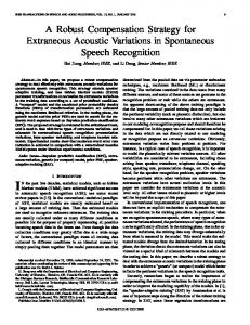
2.1. General Codec Structure Modern audio codecs and speech codecs typically exhibit a structure as shown in Figure 1. This scheme consists of three main components: (1) a core-coder (i.e. transform or speech coder) which provides a high quality and largely wave-form preserving representation of low frequency signal components; (2)
Uncompressed PCM Audio L
Spatial / Stereo Encoder and Downmix
LP
Bitstream De-Multiplex
R Core Decoder
HP
low freq.
Bandwidth Extension Decoder
high freq. Bandwidth Extension Encoder
Core Encoder
low freq.
high freq.
Combine
Spatial / Stereo Decoding and Upmix L
Bitstream Multiplex
a)
R
Uncompressed PCM Audio
b)
Fig. 1: General structure of a modern audio codec with a core codec accompanied by parametric tools for coding of bandwidth extension and stereo signals. USAC closely follows this coding paradigm. Figure 1 a) shows the encoder. Figure 1 b) shows the corresponding decoder structure. Bold arrows indicate audio signal flow. Thin arrows indicate side information and control data. a parametric bandwidth extension, such as Spectral Band Replication (SBR) [2], which reconstructs the high frequency band from replicated low frequency portions through the control of additional parameters; and (3) a parametric stereo coder, such as “Parametric Stereo” [1, 9], which represents stereo signals with the help of a mono downmix and a corresponding set of inter-channel level, phase, and correlation parameters. For low bitrates the parametric tools are able to reach much higher coding efficiency with a good quality / bitrate trade-off. At higher bitrates, where the core coder is able to handle a wider bandwidth and also discrete coding of multiple channels, the parametric tools can be selectively disabled. 2.2. HE-AACv2 General transform coding schemes, such as AAC [1, 2], rely on a sink model motivated by the human auditory system. By means of this psychoacoustic model, temporal and simultaneous masking is exploited for irrelevance removal. The resulting audio coding scheme is based on three main
AES 132nd Convention, Budapest, Hungary, 2012 April 26–29 Page 2 of 22
Neuendorf et al.
MPEG Unified Speech and Audio Coding
steps: (1) a time/frequency conversion; (2) a subsequent quantization stage, in which the quantization error is controlled using information from a psychoacoustic model; and (3) an encoding stage, in which the quantized spectral coefficients and corresponding side information are entropy-encoded. The result is a highly flexible coding scheme, which adapts well to all types of input signals at various operating points. To further increase the coding efficiency at low bitrates, HE-AACv2 combines an AAC core in the low frequency band with a parametric bandwidth and stereo extension. Spectral Band Replication (SBR) [2] reconstructs the high frequency content by replicating the low frequency signal portions, controlled by parameter sets containing level, noise, and tonality parameters. “Parametric Stereo” [1, 9] is capable of representing stereo signals by a mono downmix and corresponding sets of inter-channel level, phase, and correlation parameters. 2.3. AMR-WB+ Speech coding schemes, such as AMR-WB [4, 5], rely on a source model motivated by the mechanism of human speech production. These schemes typically have three major components: (1) a short-term linear predictive coding scheme (LPC), which models the vocal tract; (2) a long-term predictor (LTP) or “adaptive codebook”, which models the periodicity in the excitation signal from the vocal chords; and (3) an “innovation codebook”, which encodes the non-predictive part of the speech signal. AMR-WB follows the ACELP approach which uses an algebraic representation for the innovative codebook: a short block of excitation signal is encoded as a sparse set of pulses and associated gain for the block. The pulse codebook is represented in algebraic form. The encoded parameters in a speech coder are thus: the LPC coefficients, the LTP lag and gain, and the innovative excitation. This coding scheme can provide high quality for speech signals even at low bitrates. To properly encode music signals, in AMR-WB+ the time domain speech coding modes were extended by a transform coding mode for the excitation signal (TCX). The AMR-WB+ standard also has a low rate parametric high frequency extension as well as parametric stereo capabilities. 3.
THE MPEG UNIFIED SPEECH AND AUDIO
CODING WORKITEM Addressing the obvious need for an audio codec that can code speech and music equally well, ISO/IEC MPEG issued a Call for Proposal (CfP) on Unified Speech and Audio Coding (USAC) within MPEG-D [10] at the 82nd MPEG Meeting in October 2007. The responses to the Call were evaluated in an extensive listening test, with result that the joint contribution from Fraunhofer IIS and VoiceAge Corp. was selected as reference model zero (RM0) at the 85th MPEG meeting in summer 2008 [11]. Even at that point the system fulfilled all requirements for the new technology, as listed in the CfP [12]. In the subsequent collaborative phase the RM0 base system was further refined and improved within the MPEG Audio Subgroup until early 2011 when the technical development was essentially finished. The mentioned improvements were introduced by following a well defined core experiment process. In this manner further enhancements from Dolby Labs., Philips, Samsung, Panasonic, Sony and NTT Docomo were integrated into the system. After technical completion of the standard, the MPEG Audio Subgroup conducted another comprehensive subjective Verification Test in summer 2011. The results of these tests are summarized in Section 5. The standard reached International Standard (IS) stage in early 2012 by achieving a positive balloting vote from ISO’s National Bodies voting for the standard [13]. 4.
TECHNICAL DESCRIPTION
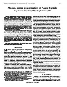
4.1. System Overview USAC preserves the same overall structure of HEAACv2 as depicted in Figure 1. An enhanced SBR tool serves as a bandwidth extension module, while MPEG Surround 2-1-2 supplies parametric stereo coding functionality. The core coder consists of an AAC based transform coder enhanced by speech coding technology. Figure 2 gives a more detailed insight into the workings of the USAC core decoder. Since in MPEG the encoder is not normatively specified, implementers are free to choose their own encoder architecture as long as it produces valid bitstreams. As a result,
AES 132nd Convention, Budapest, Hungary, 2012 April 26–29 Page 3 of 22
Neuendorf et al.
MPEG Unified Speech and Audio Coding
All AAC tools for discrete stereo or multi-channel operation are included in USAC. As a consequence, USAC can be operated in a mode equivalent to AAC.
Bitstream De-Multiplex Arithm. Dec.
Scalefactors
ACELP
Inv. Quant.
LPC Dec.
Scaling
LPC to Freq. Dom.
LPC Synth Filter
MDCT (time-warped)
FAC
Windowing, Overlap-Add Bandwidth Extension
Stereo Processing
Uncompressed PCM Audio
Fig. 2: Overview of USAC core decoder modules. The main decoding path features a Modified Discrete Cosine Transform (MDCT) domain coding part with scalefactor based or LPC based noise shaping. An ACELP path provides speech coder functionality. The Forward Aliasing Cancellation (FAC) enables smooth and flawless transitions between transform coder and ACELP. Following the core decoder, bandwidth extension and stereo processing is provided. Bold black lines indicate audio signal flow. Thin arrows indicate side information and control data. USAC provides complete freedom of encoder implementation and - just like any MPEG codec - permits continuous performance improvement even years after finalization of the standardization process. USAC retains all capabilities of AAC. In Figure 2 the left signal path resembles the AAC coding scheme. It comprises the function of entropy decoding (arithmetic decoder), inverse quantization, scaling of the spectral coefficients by the means of scalefactors and inverse MDCT transform. With respect to the MDCT, all flexibility inherited from AAC regarding the choice of the transform window, such as length, shape and dynamic switching is maintained.
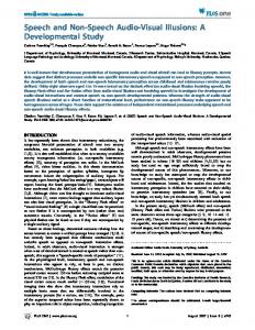
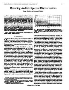
In addition, USAC introduces new technologies which offer increased flexibility and enhanced efficiency. The AAC Huffman decoder was replaced by a more efficient context-adaptive arithmetic decoder. The scalefactor mechanism as known from AAC can control the quantization noise shaping with a fine spectral granularity. If appropriate, it can be substituted by a Frequency Domain LPC Noise Shaping (FDNS) mechanism which consumes fewer bits. The USAC MDCT features a larger set of window lengths. The 512 and 256 MDCT block sizes complement the AAC 1024 and 128 sizes, providing a more suitable time-frequency decomposition for many signals. 4.2. Core-Coder In the following subsections each of the technologies employed in the core coder are described in more detail. 4.2.1. Arithmetic Coder In the transform-coder path, a context adaptive arithmetic coder is used for entropy coding of the spectral coefficients. The arithmetic coder works on pairs of two adjacent spectral coefficients (2-tuples). These 2-tuples are split into three parts: (1) the sign bits; (2) the two most significant bit-planes; (3) the remaining least significant bit-planes. For the coding of the two most significant bit-planes, one out of 64 cumulative frequency tables is selected. This selection is derived from a context, which is modeled by previously coded 2-tuples (see Figure 3). The remaining least significant bits are coded using one out of three cumulative frequency tables. This cumulative frequency table is chosen depending on the magnitude of the most-significant bits in the two uppermost bit-planes. The signs are transmitted separately at the end of the spectral data. This algorithm allows a saving from 3 to more than 6% of the overall bitrate over AAC Huffman coding while showing comparable complexity requirements. [14] 4.2.2. Quantization Module A scalar quantizer is used for the quantization of spectral coefficients. USAC supports two different quantization schemes, depending on the applied
AES 132nd Convention, Budapest, Hungary, 2012 April 26–29 Page 4 of 22
Neuendorf et al.
MPEG Unified Speech and Audio Coding
2-tuples decoded not considered for the context 2-tuples not yet decoded
Frequency
2-tuples already decoded considered for the context 2-tuples to decode
Time
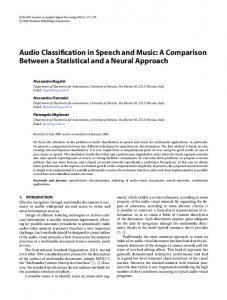
Fig. 3: Context Adaptive Arithmetic Coding. noise shaping: (1) a non-uniform quantizer is used in combination with scalefactor based noise shaping. The scalefactor based noise shaping is performed on the granularity of pre-defined scalefactor bands. To allow for an additional noise shaping within a scalefactor band, a non-uniform quantization scheme is used [15]. In the non-uniform quantizer the quantization intervals get larger with higher amplitude. Thus, the increase in signal-to-noise ratio with rising signal energy is lower than in a uniform quantizer. (2) A uniform quantizer is used in combination with LPC based noise shaping. The LPC based noise shaping is able to model the spectral envelope continuously and without subdivision in fixed scalefactor bands. This alleviates the need for an extra intra-band noise shaping. 4.2.3. Noise Shaping using Scalefactors or LPC USAC relies on two tools to shape the coding noise when encoding the MDCT coefficients. The first tool is based on a perceptual model and uses a set of scalefactors applied to frequency bands. The second tool is based on linear predictive modeling of the spectral envelope combined with a first-order filtering of the transform coefficients which achieves both frequency-domain noise shaping and sampleby-sample time-domain noise shaping. This sec-
ond noise shaping tool, called FDNS for FrequencyDomain Noise Shaping, can be seen as a combination of perceptual weighting from speech coders and Temporal Noise Shaping (TNS). Both noise shaping tools are applied in the MDCT domain. The scalefactor approach is more adapted to stationary signals because the noise shaping stays constant over the whole MDCT frame whereas FDNS is more adapted to dynamic signals because the noise shaping evolves smoothly over time. Since the perceptual model using scalefactors is already well documented [15], only FDNS is described below. When LPC based coding is employed, one LPC filter is decoded for every window within a frame. Depending on the decoded mode, there may be one up to four LPC filters per frame, plus another filter when initiating LPC based coding. Using these LPC coefficients, FDNS operates as follows (as seen at the decoder): for every window, the LPC parameters are converted into a set of M=64 gains gk [m] in the frequency domain, defining a coarse spectral noise shape at the overlap point between two consecutive MDCT windows. Then, in each of the M bands, a first-order inverse filtering is performed on the spectral coefficients Cmf [k], as shown in Figure 4, to interpolate the noise level within the window boundaries noted as instants A and B in Figure 5. Therefore, instead of the conventional LPC coefficient interpolation and time-domain filtering as done in speech codecs, the process of noise shaping is applied only in the frequency domain. This provides two main advantages: first, the MDCT can be applied to the original signal (rather than the weighted signal as in speech coding), allowing proper TDAC on the transition between scalefactor and LPC based noise shaping; and second, because of the “TNSlike” feature of FDNS, the noise shape is finely controlled on a sample-by-sample basis rather than on a frame-by-frame basis. 4.2.4. (Time-Warped) MDCT The Modified Discrete Cosine Transform (MDCT) is well suited for harmonic signals with a constant fundamental frequency F0 . In this case only a sparse spectrum with a limited number of relevant lines has to be coded. But when F0 is rapidly varying, typically for voiced speech, the frequency modulation of the individual harmonic lines leads to a smeared spectrum and therefore a loss in coding
AES 132nd Convention, Budapest, Hungary, 2012 April 26–29 Page 5 of 22
Neuendorf et al.
MPEG Unified Speech and Audio Coding
C1[k]
C1f [k]
Noise gains g1[m] calculated at time position A
Inverse Filter 1 C2f [k]
C2 [k]
Inverse Filter 2 Spectral C3f [k] Coeffs
CMf [k]
Noise gains g2[m] calculated at time position B
A C3 [k]
IMDCT
y[n]
Inverse Filter 3
C
CM[k]
B
time axis (n)
Inverse Filter M
Fig. 5: Effect on noise shape of FDNS processing. g1[m] and g2[m]
Fig. 4: FDNS processing. gain. The Time Warped MDCT (TW-MDCT) [16] overcomes this problem by applying a variable resampling within one block prior to the transform. This resampling reduces or ideally completely removes the variation of F0 . The reduction of this variation causes a better energy compaction of the spectral representation and consequently an increased coding gain compared to the classic MDCT. Furthermore, a careful adaptation of the window functions and of the average sampling frequency retain the perfect reconstruction property and the constant framing of the classic MDCT. The necessary warp information needed for the inverse resampling at the decoder is efficiently coded and part of the side information in the bitstream. 4.2.5. Windowing In terms of windows and transform block sizes, USAC combines the well-known advantages of the 50% overlap MDCT windows of length 2048 and 256 (transform core of 1024 and 128) from AAC with the higher flexibility of TCX with additional transform sizes of 512 and 256. The long transform windows allow optimal coding of distinctly tonal signals, while the shorter windows with shorter overlaps allow coding of signals with an intermediate and highly varying temporal structure. With this set of windows the codec can adapt its coding mode much more closely to the signal than possible before. Figure 6
shows the window and transform lengths and general shapes. Similar to the start and stop windows of AAC, transitional windows accommodate the variation in transform length and coding mode [17]. In the special case of transitions to and from ACELP, the Forward Aliasing Cancellation takes effect (see Section 4.2.9). Further flexibility is achieved by allowing a 768 sample based windowing scheme. In this mode all transform and windows sizes are reduced to 34 th of the above mentioned numbers. This allows even higher temporal resolution, which is particularly useful in situations where the codec runs on a reduced core sampling rate. This mode is combined with a 3 : 8 QMF filterbank upsampling in eSBR (see Section 4.3.2) such that a higher audio bandwidth can be achieved at the same time. 4.2.6. Quantization of LPC coefficients USAC includes a new variable bitrate quantizer structure for the LPC filter coefficients. Rather than using trained codebooks which are memoryconsuming, an extremely memory-efficient 2-stage approach based on algebraic vector quantization (AVQ, see Section 4.2.8) is used. An additional advantage of this approach is that the spectral distortion can be essentially maintained below a preset threshold by implicit bit allocation, thus making LPC quantization much less signal dependent. Another aspect of this variable bitrate quantizer is the application of LPC prediction within a frame.
AES 132nd Convention, Budapest, Hungary, 2012 April 26–29 Page 6 of 22
Neuendorf et al.
128
MPEG Unified Speech and Audio Coding
t
Fig. 6: Schematic overview over the allowed MDCT windows in USAC. Dotted lines indicate transform core boundaries. Bottom right shows ACELP window for reference. Transitional windows are not shown. Specifically, if more than one LPC filter is transmitted within a frame, a subset of these filters are quantized differentially. This decreases significantly the bit consumption of the LPC quantizer in particular for speech signals. In this 2-stage quantizer, the first stage uses a small trained codebook as a first coarse approximation and the second stage uses a variable-rate AVQ quantizer in a split configuration (16-dimensional LPC coefficients quantized in 2 blocks of 8 dimensions). 4.2.7. ACELP The time domain encoder in USAC is based on stateof-the-art ACELP speech compression technology. Several speech coding standards, in particular in cellular systems, integrate ACELP. The ACELP module in USAC uses essentially the same components as in AMR-WB+ [6] but with some improvements. LPC quantization was modified such that it is variable in bitrate (as described in Section 4.2.6). And the ACELP technology is more tightly integrated with other components of the codec. In ACELP mode, every quarter frame of 256 samples is split into 4 subframes of 64 samples (or for quarter frames of 192 samples it is split into 3 subframes of 64 samples). Using the LPC filter for that quarter frame (either a decoded filter or an interpolated filter depending on the position in a frame) each subframe is encoded as an excitation signal passed through
the LPC filter. The excitation signal is encoded as the sum of two components: a pitch (or LTP) component (delayed, scaled version of the past excitation with properly chosen delay; also called adaptive codebook (ACB)) and an innovative component. The latter is encoded as a sparse vector formed by a series of properly placed non-zero impulses and corresponding signs and global gain. Depending on the available bitrate, the ACELP innovation codebook (ICB) size can be either of 20, 28, 36, 44, 52 or 64 bits. The more bits are spent for the codebook, the more impulses can be described and transmitted. Besides the LPC filter coefficients, the parameters transmitted in an ACELP quarter frame are: Mean energy LTP pitch LTP filter ICB Gains
2 bits 9 or 6 bits 1 bit 20, 28, 36, 44, 52 or 64 bits 7 bits
All parameters are transmitted every subframe (every 64 samples), except the Mean energy which is transmitted once every ACELP quarter frame. 4.2.8. Algebraic Vector Quantization Algebraic Vector Quantization (AVQ) is a structured quantization technique requiring very little memory and is intended to quantize signals with uniform distribution. The AVQ tool used in USAC is another component taken from AMR-WB+. It is used to quantize LPC coefficients and FAC parameters (see Section 4.2.9). The AVQ quantizer is based on the RE8 lattice [18], which has a nice densely packed structure in 8 dimensions. An 8-dimensional vector in RE8 can be represented by a so-called “leader” along with a specific permutation of the leader components. Using an algebraic process, a unique index for each possible permutation can be calculated. Leaders with statistical equivalence can be grouped together to form base codebooks which will define the layers of the indexing. Three base codebooks have been defined: Q2, Q3 and Q4 where indexing all permutations of the selected leaders consumes 8, 12 and 16 bits respectively. To extend the quantizer to even greater size, instead of continuing to add bigger base codebook (Q5 and over), a Voronoi extension has been added to extend algebraically the base codebook. With each additional 8 bits (1 bit per dimension),
AES 132nd Convention, Budapest, Hungary, 2012 April 26–29 Page 7 of 22
Neuendorf et al.
MPEG Unified Speech and Audio Coding
Bit Demux
Zero memory
Q3 + extension of 16 bits Q4 + extension of 8 bits Q3 + extension of 8 bits
AVQ
IDCTIV
1/W(z)
Q4 Q3
LPC1
FAC synthesis LPC2
Q2
FAC synthesis
FAC synthesis
IMDCT output
ACELP -
Fig. 7: Embedded structure of the AVQ quantizer.
ACELP
+
ACELP contribution (ZIR + folded synth) +
the Voronoi extension doubles the size of the codebook. Therefore Q3 and Q4 extended by a factor of 2 will use 20 and 24 bits respectively, and for a factor of 4, they will use 28 and 32 bits respectively. Hence, although the first layer (Q2) requires 8 bits, each additional layer in the AVQ tool adds 4 bits to the indexing (1/2 bit resolution). It should be noted that Q2 is a subset of Q3. In the USAC bitstream, the layer number (Qn) is indexed separately using an entropy code since small codebooks are more probable than large codebooks. 4.2.9. Transition Handling The USAC core combines two domains of quantization, the frequency domain which uses MDCT with overlapped windows and the time domain which uses ACELP with rectangular non-overlapping windows. To compute the synthesis signal, a decoded MDCT frame relies on time domain aliasing cancellation (TDAC) of adjacent windows whereas the decoded ACELP excitation uses the LPC filtering. To handle transitions in an effective way between the two modes, a new tool, called “Forward Aliasing Cancellation” (FAC) has been developed. This tool “Forwards” to the decoder the “Aliasing Cancellation” data required to retrieve the signal from the MDCT frame usually done by TDAC. Hence, at transitions between the two domains, additional parameters are transmitted, decoded and processed to obtain the FAC synthesis as shown in Figure 8. To
Synthesis in the original domain
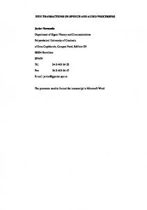
Fig. 8: Forward Aliasing Cancellation applied at transitions between ACELP and MDCT-encoded modes. recover the complete decoded signal, the FAC synthesis is merely combined with the windowed output of the MDCT. In the specific case of transitions from ACELP to MDCT, the ACELP synthesis and following zero-input response (ZIR) of the LPC filter is windowed, folded and used as a predictor, to reduce the FAC bit consumption. 4.3. enhanced SBR Bandwidth Extension 4.3.1. Basic Concept of SBR The Spectral Band Replication (SBR) technology was standardized in MPEG-4 in 2003, as an integral part of High Efficiency AAC (HE-AAC). The tool is a high frequency reconstruction tool that operates on a core coder signal, and extends the bandwidth of the output based on the available lowband signal and control data from the encoder. The principle of SBR and HE-AAC is elaborated on in [2, 19, 20]. The SBR decoder operating on the AAC as standardized in MPEG-4, is depicted in Figure 9. The
AES 132nd Convention, Budapest, Hungary, 2012 April 26–29 Page 8 of 22
Neuendorf et al.
MPEG Unified Speech and Audio Coding
SBR Decoder
signal fs bitstream
QMF Analysis (32 bands)
AAC lowband signal QMF Synthesis (64 bands)
AAC Decoder SBR processing
50
audio output 2 fs
Level [dB]
audio
Frequency range used for HF patch and estimation of filter coefficients
Frequency range of first HF patch
0
A
B
Frequency range of second HF patch
-50
SBR
0
data
system shown is a dual rate system where the SBR algorithm operates in a QMF domain and produces an output of wider bandwidth and twice the sampling rate of that of the core coded signal going into the SBR module. The SBR decoder generates a high frequency signal by copy-up methods in the QMF domain as indicated in Figure 10. An inverse filtering is carried out within each QMF subband in order to adjust the tonality of the subband in accordance with parameters sent from the encoder. The high frequency regenerated signal is subsequently envelope adjusted based on time/frequency tiles of envelope data transmitted from the encoder. During the envelope adjustment, additional noise and sinusoids are optionally added according to parametric data sent from the encoder. 4.3.2. Alternative Sampling Rate Ratios MPEG-4 SBR was initially designed as a 2:1 system. Here, typically 1024 core coder samples are fed into a 32 band analysis QMF filterbank. The SBR tool performs a 2:1 upsampling in the QMF domain. After reconstructing the high frequency content, the signal is transformed back to time domain by means of 64 band synthesis QMF filterbank. This results in 2048 time domain samples at twice the core coder sampling rate. For USAC, the traditional 2:1 system was extended by two additional operating modes. First, to cope with low core coder sampling rates, which are usually used at very low bitrates, a variation of the SBR module similar as standardized in DRM (Digital Radio Mondiale) has been adopted into the USAC stan-
10 15 Frequency [kHz] HF Generated highband signal
20
50
1 Level [dB]
Fig. 9: Basic outline of SBR as used in MPEG-4 in combination with AAC.
5
2
3 Frequency ranges of inverse filtering bands
0
-50 0
5
10 Frequency [kHz]
15
20
Fig. 10: Basic principle of copy-up based SBR as used in MPEG-4 in combination with AAC. dard. In this mode, the 32 band analysis QMF filterbank is replaced by a 16 band QMF analysis filterbank. Hence, the SBR module is also capable of operating as a 4:1 system, where SBR runs at four times the core coder sampling rate. In this case, the maximum output audio bandwidth the system can produce at low sampling rates is increased by a factor of two compared to that of the traditional 2:1 system. This increase in audio bandwidth results in a substantial improvement in subjective quality at very low bitrates. Second, USAC is also capable of operating in an 8:3 operating mode. In this case, a 24 band analysis QMF filterbank is used. In combination with a 768 core coder frame size, this mode allows for the best trade-off between optimal core-coder sampling rate and high temporal SBR resolution at medium bitrates, e.g. 24 kbit/s. 4.3.3. Harmonic Transposition In USAC a harmonic transposer of integer order T maps a sinusoid with frequency ω into a sinusoid with frequency T ω, while preserving signal duration. This concept was originally proposed for SBR in [21], and the quality advantage over the frequency shift method, especially for complex stationary music signals, was verified in [22].
AES 132nd Convention, Budapest, Hungary, 2012 April 26–29 Page 9 of 22
Neuendorf et al.
MPEG Unified Speech and Audio Coding
USAC Core Decoder
QMF Analysis (16, 24 or 32 band)
Bitstream De-Multiplex
Transposer Regular
or (QMF based) Harmonic
Stretch & Transp. PreCross process. Products
Copy-Up
Inverse Filtering
Inter-TES Calculator Adjuster QMF Synthesis (64 band)
Envelope Adjuster Pred. Diff. or Vector Huffman Decoder Decoder (PVC) Energy Adjuster Noise Floor Adjuster Inter-TES Shaper Additional Sinusoids (Missing Harmonics)
Uncompressed PCM Audio
Fig. 11: Complete overview over the enhanced SBR of the USAC system. The figure shows the optional lower complexity QMF domain harmonic transposer, the PVC decoder and the Inter-TES decoder modules. Three orders, T = 2, 3, 4, are used in sequence to produce each part of the desired output frequency range using the smallest possible transposition order. If output above the fourth order transposition range is required, it is generated by frequency shifts. When possible, near critically sampled baseband time domains are created for the processing to minimize computational complexity. The benchmark quality transposer is based on a fine resolution sine windowed FFT. The algorithmic steps for T = 2 consist of complex filterbank analysis, subband phase multiplication by two, and filterbank synthesis with time stride twice of that of the analysis. The resulting time stretch is converted into transposition by a sampling rate change. The higher orders T = 3, 4 are generated in the same filterbank framework. For a given target subband, inputs from two adjacent source subbands are combined by interpolating phases linearly and magnitudes geometrically. Controlled by one bit per core
coder frame, the FFT transposer adaptively invokes a frequency domain oversampling by 50% based on the transient improvement method of [23]. To allow the use of USAC in low-power applications such as portable devices, an alternate, low complexity, transposer that closely follows the bandwidth extension principle of the FFT transposer can be used as shown in Figure 11. This low complexity transposer operates in a QMF domain which allows for direct interfacing with the subsequent SBR processing. The coarse resolution QMF transposer suppresses intermodulation distortion by using overlapping block processing [24]. The finer time resolution of the QMF bank itself allows for a better transient response than that of the FFT without oversampling. Moreover, a geometrical magnitude weighting inside the subband blocks reduces potential time smearing. The inherent spectral stretching of harmonic transposition can lead to a perceptual detachment of single overtones from periodic waveforms having rich overtone spectra. This effect can be attributed to the sparse overtone structure in the stretched spectral portions, since e.g. a stretching by the factor of two only preserves every other overtone. This is mitigated by the addition of cross products. These consist of contributions from pairs of source subbands separated by a distance corresponding to the fundamental frequency [23]. The control data for cross products is transmitted once per core coder frame and consists of an on/off flag and seven bits indicating the fundamental frequency in the case that the flag is set. 4.3.4. Predictive Vector Coding In order to improve the subjective quality of the eSBR tool, in particular for speech content at low bitrates, Predictive Vector Coding (PVC) is added to the eSBR tool. Generally, for speech signals, there is a relatively high correlation between the spectral envelopes of low frequency bands and high frequency bands. In the PVC scheme, this is exploited by the prediction of the spectral envelope in high frequency bands from the spectral envelope in low frequency bands, where the coefficient matrices for the prediction are coded by means of vector quantization. The block diagram of the eSBR decoder including the PVC decoder is shown in Figure 11.
AES 132nd Convention, Budapest, Hungary, 2012 April 26–29 Page 10 of 22
Neuendorf et al.
MPEG Unified Speech and Audio Coding
The analysis and synthesis QMF banks and HF generator remain unchanged, but the HF envelope adjuster is modified to process the high frequency envelopes generated by the PVC decoder. In the PVC decoder, the high frequency envelopes are generated by multiplying a prediction coefficient matrix with the low frequency envelopes. A prediction codebook in the PVC decoder holds 128 coefficient matrices. An index of the prediction coefficient matrix that provides the lowest difference between predicted and actual envelopes is transmitted as a 7 bit value in the bitstream. 4.3.5. Inter-subband-sample Temporal Envelope Shaping (Inter-TES) For transient input signals audible distortion (pre/post-echoes) can occur in the high frequency components generated by eSBR due to its limited temporal resolution. Although splitting a frame into several shorter time segments can avoid the distortion, this requires more bits for eSBR information. In contrast, Inter-TES can reduce the distortion with smaller number of bits by taking advantage of the correlation between temporal envelopes in the low and high frequency bands. Inter-TES requires 1 bit for its activation and 2 bits for an additional parameter described below. Figure 11 shows the Inter-TES module as part of the eSBR block diagram. When Inter-TES is activated, the temporal envelope of the low frequency signal is first calculated, and the gain values are then computed by adjusting the temporal envelope of the low frequency signal according to a transmitted parameter. Finally, the gain values are applied to the transposed high frequency signal including noise components. As shown in Figure 11, the shaped high frequency signal and the independent sinusoids are added if necessary, and then fed to the synthesis QMF bank in conjunction with the low frequency signal. 4.4. Stereo Coding 4.4.1. Discrete vs. Parametric Stereo Coding There are two established approaches for coding of stereophonic audio signals. Discrete stereo coding schemes strive to represent the individual waveforms of each of the two channels of a stereo signal. They utilize joint stereo coding techniques such as mid/side (M/S) coding [25] to take inter-channel re-
stereo input L
R
down downmix mix matrix
stereo output
MPS decoder
MPS encoder
core codec
decoded downmix decorrelator
M D
upmix matrix H
ˆ L ˆ R
ICC, CLD
Fig. 12: Basic structure of the MPS 2-1-2 parametric stereo encoder and decoder used in USAC. Bold lines denote audio signal paths, whereas the thin arrow denotes the flow of parametric side information. dundancy and binaural masking effects into account. Parametric stereo coding schemes [26, 27, 28], on the other hand, are designed to represent the perceived spatial sound image of the stereo signal. They utilize a compact parametric representation of the spatial sound image which is conveyed as side information in addition to a mono downmix signal and used in the decoder to recreate a stereo output signal. Parametric stereo coding is typically used at low target bitrates, where it achieves a higher coding efficiency than discrete stereo coding. USAC extends, combines, and integrates these two stereo coding schemes, thus bridging the gap between them. 4.4.2. Parametric Stereo Coding with MPEG Surround 2-1-2 Parametric stereo coding in USAC is provided by an MPEG Surround 2-1-2 (MPS 2-1-2) downmix/upmix module which was derived from MPEG Surround (MPS) [9, 29]. The signal flow of the MPS 2-1-2 processing is depicted in Figure 12. At the encoder, MPS calculates a downmix signal and parameters that capture the essential spatial properties of the input channels. These spatial parameters, namely the inter-channel level differences (CLDs) and inter-channel cross-correlations (ICCs), are only updated at a relatively low time-frequency resolution based on the limits of the human auditory system to perceive spatial phenomena, thus requiring a bitrate of only a few kbit/s. In the decoder, a decorrelated signal D, generated from the downmixed input signal M , is fed along with M into the upmixing matrix H, as depicted in the right dashed box in Figure 12. The coefficients
AES 132nd Convention, Budapest, Hungary, 2012 April 26–29 Page 11 of 22
Neuendorf et al.
MPEG Unified Speech and Audio Coding
Stereo sound quality is enhanced by utilizing phase parameters in addition to CLDs and ICCs. It is wellknown that inter-channel phase differences (IPDs) can play an important role in stereo image quality, especially at low frequencies [26]. In contrast to parametric stereo coding in MPEG-4 HE-AAC v2 [1], phase coding in USAC only requires the transmission of IPD parameters, since it has been shown that the overall phase differences parameters (OPDs) can be analytically derived from the other spatial parameters on the decoder side [30, 31]. The USAC parametric stereo phase coding can handle anti-phase signals by applying an unbalanced weighting of the left and right channels during downmixing and upmixing processes. This improves stability for stereo signals where out-of-phase signal components would otherwise cancel each other in a simple mono downmix. 4.4.3. Unified Stereo Coding In a parametric stereo decoder, the stereo signal is reconstructed by an upmix matrix from the mono downmix signal and a decorrelated version of the downmix, as shown in the right part of Figure 12. MPS enhances this concept by optionally replacing parts of the decorrelated signal with a residual waveform signal. This ensures scalability up to the same transparent audio quality achievable by discrete stereo coding, whereas the quality of a parametric stereo coder without residual coding might be limited by the parametric nature of the spatial sound image description. Unlike MPS, where the residual signals are coded independently from the downmix signals, USAC tightly integrates the coding of the downmix and residual signals. As described above, in addition to CLD and ICC parameters, USAC also employs IPD parameters for coding the stereo image. The combination of parametric stereo coding involving IPD parameters and integrated residual coding is referred to as unified stereo coding in USAC. In order to minimize the residual signal, an encoder as shown in the left half of Figure 13 is used. In each frequency band, the left and right signals L and R are fed into a traditional mid/side (i. e. sum/difference) transform. The resulting signals are gain normalized by a factor c. A prediction of the scaled difference signal is made by
L
M
M'
+ c α R
-
+
+ c
Core Codec
of H are determined by the parametric spatial side information generated in the encoder.
res
L'
+ 1 2c
α
+ res'
1 2c
+ R'
Fig. 13: Block diagram of unified stereo encoder (left) and decoder (right). multiplication of the mid (i. e. sum) signal M with a complex-valued parameter α. Both c and α are a function of the CLD, ICC, and IPD parameters. The resulting M and res signals are then fed into the 2-channel USAC core encoder which includes a correspondingly modified psychoacoustic model and can either encode the downmix and residual signal directly or can encode a mid/side transformed version known as pseudo L/R signal. The decoder follows the inverse path, as depicted in the right half of Figure 13. The optimal order of MPS and SBR processing in the USAC decoder depends on the bandwidth of the residual signal. If no or a bandlimited residual signal is used, it is advantageous to apply mono SBR decoding followed by MPS 2-1-2 decoding. At higher bitrates, where the residual signal can be coded with the same bandwidth as the downmix signal, it is beneficial to apply MPS 2-1-2 decoding prior to stereo SBR decoding. 4.4.4. Transient Steering Decorrelator Applause signals are known to be a challenge for parametric stereo coding. In a simple model, applause signals can be thought of as being composed of a quasi-stationary noise-like background sound originating from the dense, far-off claps, and a collection of single, prominently exposed claps. Both components have very different properties that need to be addressed in the parametric upmix [32]. Upmixed applause signals usually lack spatial envelopment due to the insufficiently restored transient distribution and are impaired by temporally smeared transients. To preserve a natural and convincing spatio-temporal structure, a decorrelating technique is needed that can handle both of the extreme signal characteristics as described by the applause model. The Transient Steering Decorrelator (TSD) is an im-
AES 132nd Convention, Budapest, Hungary, 2012 April 26–29 Page 12 of 22
Neuendorf et al.
mono downmix M1
MPEG Unified Speech and Audio Coding
ˆ L
M
decorrelator
D1
transient separation
upmix matrix D H
stereo output ˆ R
M2
D2
transient decorrelator
ICC, CLD and TSD data
Fig. 14: TSD (highlighted by gray shading) within the MPS 2-1-2 module of the USAC decoder. plementation of such a decorrelator [33]. TSD basically denotes a modification of the MPS 2-1-2 processing within USAC. The block diagram of the TSD embedded in the upmix box of the MPS 2-1-2 decoder module is shown in Figure 14. The mono downmix is split by a transient separation unit with fine temporal granularity into a transient signal path and a non-transient signal path. Decorrelation is achieved separately within each signal path through specially adapted decorrelators. The outputs of these are added to obtain the final decorrelated signal. The non-transient signal path M1 utilizes the MPS 2-1-2 late-reverbtype decorrelator. The transient signal path M2 comprises a parameter-controlled transient decorrelator. Two frequency independent parameters that entirely guide the TSD process are transmitted in the TSD side information: a binary decision that controls the transient separation in the decoder, and phase values that spatially steer the transients in the transient decorrelator. Spatial reproduction of transient events does not require fine spectral granularity. Hence, if TSD is active, MPS 2-1-2 may use broadband spatial cues. 4.4.5. Complex Prediction Stereo Coding MPS 2-1-2 and unified stereo coding employ complex QMF banks, which are shared with the SBR bandwidth extension tool. At high bitrates, however, the SBR tool is typically not operated, while unified stereo coding would still provide an improved coding efficiency compared to traditional joint stereo coding techniques such as mid/side coding. In order to achieve this improved coding efficiency without
the computational complexity caused by the QMF banks, USAC provides a complex prediction stereo coding tool [34] that operates directly in the MDCT domain of the underlying transform coder. Complex prediction stereo coding applies linear predictive coding principles to minimize inter-channel redundancy in mid signal M and side signal S. The prediction technique is able to compensate for interchannel phase differences as it employs a complexvalued representation of either M or S in combination with a complex-valued prediction coefficient α. The redundant coherent portions between M and S signal are minimized - and the signal compaction maximized - by subtracting from the smaller of the two a weighted and phase-adjusted version of the larger one - the downmix spectrum D - leading to a residual spectrum E. Downmix and residual are then perceptually coded and transmitted along with prediction coefficients. Figure 15 shows the block diagram of a complex prediction stereo encoder and decoder. The key here is to utilize a complex-valued downmix spectrum D obtained from a modulated complex lapped transform (MCLT) [35] representation for which the MDCT is the real part and whose imaginary part is the modified discrete sine transform (MDST). Given that in USAC, M and S are obtained via real-valued MDCTs, an additional realto-imaginary (R2I) transform is required so that D can be constructed in both encoder and decoder [34]. In USAC, an efficient approximation of the R2I transform is utilized that operates directly in the frequency domain and does not increase the algorithmic delay of the coder. 4.5. System Aspects 4.5.1. Profiles MPEG defines profiles as a combination of standardized tools. While all tools are always retained in the standard, the profile provides a subset or combination of tools that serve specific industry needs. A profile typically has several levels, where higher levels usually entail increasing complexity. Although there are many profiles defined in MPEG-4 Audio, the most successful and widely adopted ones are the ”AAC family” of profiles, i.e. the ”AAC profile”, the ”HE-AAC v1 profile” and the ”HE-AAC v2 profile”. The AAC family of profiles, as outlined in Figure 16,
AES 132nd Convention, Budapest, Hungary, 2012 April 26–29 Page 13 of 22
Neuendorf et al.
MPEG Unified Speech and Audio Coding
L
DR
MDCT
Q
AAC LC
R2I DR
αQ
α optim.
R
SBR
PS
DI Mux
Sum/Diff
MDCT
a)
αR
αI
-
-
AAC Profile High Efficiency AAC Profile
E Q
High Efficiency AAC v2 Profile b)
L
DR
α
Q
αR Q
-1
DI
αI
E
AAC LC
Sum/Diff
Demux
R2I
R +
+
MDCT-1
DR
MDCT-1
Q-1
Fig. 16: The AAC Family of profiles.
SBR
PS
USAC Mono/Stereo
Extended High Efficiency AAC Profile Fig. 17: The Extended HE AAC profile.
Fig. 15: Block diagram of complex prediction stereo encoder a) and decoder b). are hierarchical. The structure of the profiles ensure that: 1. An AAC decoder plays: AAC LC (Low Complexity) 2. An HE-AAC decoder plays: AAC LC and SBR 3. An HE-AAC v2 decoder plays: AAC LC, SBR, and PS In the MPEG USAC standard, two profiles are defined: 1. Extended HE-AAC Profile 2. USAC Baseline Profile The Baseline USAC profile contains the complete USAC codec except for the following tools: 1. DFT transposer 2. Time-warped filterbank
3. Fractional delay decorrelator The Extended High Efficiency AAC profile contains all of the tools of the High Efficiency AAC v2 profile and is as such capable of decoding all AAC family profile streams. In addition, the profile incorporates mono/stereo capability of the Baseline USAC profile, as outlined in Figure 17. The Extended High Efficiency AAC profile includes the mono/stereo capability of USAC since this part of USAC (when operated at low rates) provides the consistent performance across content types at low bitrates. This provides a natural evolution of one of the most successful families of profiles in MPEG Audio. The Baseline USAC profile provides a clear standalone profile for applications and usage scenarios where the capability of supporting the AAC family is not relevant. The worst case decoding complexity of both profiles is listed in Table 1 and 2. The complexity numbers are indicated in terms of Processor Complexity Units (PCU) and RAM Complexity Units (RCU). PCUs are specified in MOPS, and RCUs are expressed in kWords (1000 words).
AES 132nd Convention, Budapest, Hungary, 2012 April 26–29 Page 14 of 22
Neuendorf et al.
Level
Max. channels
1 2 3 4
1 2 5.1 5.1
MPEG Unified Speech and Audio Coding
Max. sampling rate [kHz] 48 48 48 96
Max. PCU
Max. RCU
7 12 31 62
6 11 28 28
Table 1: USAC Baseline Profile processor and RAM complexity depending on decoder level. Level
Max. channels
1 2 3 4 5
n/a 2 2 5.1 (Note 2) 5.1 (Note 2)
Max. sampling rate [kHz] n/a 48 (Note 1) 48 (Note 1) 48 96
Max. PCU
Max. RCU
n/a 12 15 25 49
n/a 11 11 28 28
Table 2: Extended High Efficiency AAC Profile processor and RAM complexity depending on decoder level. Note 1: Level 2 and Level 3 differ for the decoding of HE-AACv2 bitstreams with respect to the max. AAC sampling rate in case Parametric Stereo data is present [1]. Note 2: USAC is limited to mono or stereo. Each profile consists of several levels. The levels are defined hierarchically and denote the worst case complexity for a given decoder configuration. A higher level indicates an increased decoder complexity, which goes along with support for a higher number of channels or a higher output sampling rate. First implementions of an Extended High Efficiency Profile decoder indicate similar complexity and memory requirements as for High Efficiency AAC v2 profile, when operated at the same level. 4.5.2. Transport The way of signaling and transport of the USAC payload is very similar to MPEG-4 HE-AACv2. As for HE-AACv2, the concept of a signaling within MPEG-4 Audio is supported. For this purpose, a new Audio Object Type (AOT) for USAC is defined within the MPEG-4 AudioSpecificConfig. The AudioSpecificConfig can also carry the UsacConfig data, which is needed to properly set up the decoder. The mandatory explicit signaling of all USAC de-
coder tools, such as SBR and PS, avoids several problems of HE-AACv2. For the reason of backward compatibility to decoders not supporting SBR or Parametric Stereo, an implicit signaling was introduced in HE-AACv2. As a consequence, a decoder at start-up was not able to clearly determine output sampling rate, channel configuration or number of samples per frame. In contrast to HE-AACv2, a USAC decoder unambiguously determines its configuration by reading the UsacConfig data at startup. A set of audioProfileLevelIndication values allows for the signaling of the required decoder profile and level. Like for HE-AACv2, the frame-wise payload (UsacFrame) directly corresponds to MPEG-4 access units. In combination with the MPEG-4 signaling, a multitude of transport formats natively supports the carriage of USAC. For streaming applications, the use of e.g. LATM/LOAS [1], IETF RFC 3016 [36] and RFC 3640 [37] is possible. For broadcasting applications, MPEG-2 transport stream [38] may be used. Finally, the MP4 and 3GPP file formats [39, 40] provide support for file-based applications. MP4 and 3GPP file format based applications can now benefit from mandatory edit list support in USAC decoders to provide an exact time alignment: a decoder can reconstruct the signal with the exact starting and ending times, as compared to the original signal. Thus, additional samples at the beginning or end, introduced by frame-based processing and other buffering within the codec, are removed on the decoder side. 4.5.3. Random Access Various tools in USAC may exploit inter-frame correlation to reduce the bit demand. In SBR and MPS 2-1-2, time differential coding relative to the previous frame may be used. The arithmetic coder may refer to a context based on the previous frame. Though these techniques improve coding efficiency for the individual frames, it comes at the cost of introducing a source of inter-frame dependencies. This means that a given frame may not be decoded without the knowledge of the previous frame. In case of transmission over an error prone channel or in case of broadcasting where a continuously transmitted stream is received and shall be decoded starting with a randomly received first frame,
AES 132nd Convention, Budapest, Hungary, 2012 April 26–29 Page 15 of 22
Neuendorf et al.
MPEG Unified Speech and Audio Coding
these inter-frame dependencies can make the tune-in phase challenging. For the reasons listed above, USAC audio streams contain random access frames that can be decoded entirely independent from any previous frame (“independent frames”). The information whether a frame acts as an “independent frame” is conveyed in the first bit of the USAC frame, and can be easily retrieved. The frame independence is achieved by resetting the arithmetic coder context and forcing SBR and MPS 2-1-2 to frequency-differential coding only. The independent frame serves as safe starting points for random access decoding, also after a frame loss. In addition to the indication of independent frames, great importance was paid to an explicit signaling of potential core-coder frame dependent information. Wherever window size, window shape or the need for FAC data is usually derived from the previous frame, this information can be unambiguously determined from the payload of any given independent frame. 5.
PERFORMANCE
5.1. Listening Test Description Three listening tests were performed to verify the quality of USAC. The objective of these verification tests was to confirm that the goals set out in the original Call for Proposals are met by the final standard [10, 41]. National Bodies could then take the test results as documented in the Verification Test report [42] into account when casting their final vote for USAC. Since the goal of USAC was the development of an audio codec that performs at least as good as the better of the best speech codec (AMR-WB+) and the best audio codec (HE-AACv2) around, the verification tests compared USAC to these codecs for mono and stereo at several bitrates. The results also provide the possibility to create a quality versus bitrate curve (a.k.a. rate-distortion curve) showing how the perceived quality of USAC progresses at different bitrates. The conditions included in each test are given in Tables 3 to 5. As stated above, along with USAC, two other audio coding standards were included as references: HE-AACv2 and AMR-WB+. These two reference codecs form the Virtual Codec (VC), which actually does not exist as a single technology, but is defined as the best of the HE-AACv2
Condition Hidden reference Low pass anchor at 3,5 kHz1 Low pass anchor at 7 kHz1 USAC at 8 kbit/s USAC at 12 kbit/s USAC at 16 kbit/s USAC at 24 kbit/s HE-AAC v2 at 12 kbit/s HE-AAC v2 at 24 kbit/s AMR-WB+ at 8 kbit/s AMR-WB+ at 12 kbit/s AMR-WB+ at 24 kbit/s
Label HR LP3500 LP7000 USAC-8 USAC-12 USAC-16 USAC-24 HE-AAC-12 HE-AAC-24 AMR-8 AMR-12 AMR-24
Table 3: Conditions for Test 1 (mono at low bitrates).
Condition Hidden reference Low pass anchor at 3.5 kHz1 Low pass anchor at 7 kHz1 USAC at 16 kbit/s USAC at 20 kbit/s USAC at 24 kbit/s HE-AAC v2 at 16 kbit/s HE-AAC v2 at 24 kbit/s AMR-WB+ at 16 kbit/s AMR-WB+ at 24 kbit/s
Label HR LP3500 LP7000 USAC-16 USAC-20 USAC-24 HE-AAC-16 HE-AAC-24 AMR-16 AMR-24
Table 4: Conditions for Test 2 (stereo at low bitrates).
or AMR-WB+ codecs on a given test item at a given operating point (bitrate and number of audio channels). 5.2. Test Items Twenty-four test items were used in the test, consisting of 8 items from each of three content categories: Speech, Speech mixed with Music, and Music. Test items were stereo signals sampled at 48 kHz and were approximately 8 seconds in duration. A large number of relatively short test items were used so that the items could encompass a greater diversity of content. Mono items were derived from the stereo items 1 Bandlimited but keeping the same stereo width as the original (hidden reference)
AES 132nd Convention, Budapest, Hungary, 2012 April 26–29 Page 16 of 22
Neuendorf et al.
MPEG Unified Speech and Audio Coding
Condition Hidden reference Low pass anchor at 3.5 kHz1 Low pass anchor at 7 kHz1 USAC at 32 kbit/s USAC at 48 kbit/s USAC at 64 kbit/s USAC at 96 kbit/s HE-AAC v2 at 32 kbit/s HE-AAC v2 at 64 kbit/s HE-AAC v2 at 96 kbit/s AMR-WB+ at 32 kbit/s
Label HR LP3500 LP7000 USAC-32 USAC-48 USAC-64 USAC-96 HE-AAC-32 HE-AAC-64 HE-AAC-96 AMR-32
Table 5: Conditions for Test 3 (stereo at high bitrates).
by either averaging left and right channel signals or taking only the left channel if an average resulting in significant comb filtering or phase cancellation. All items were selected to be challenging for all codecs under test. 5.3. Test Methodology All tests used the MUSHRA methodology [43]. All tests were conducted in an acoustically controlled environment (such as a commercial sound booth) using reference quality headphones. All items were concatenated to form a single file for processing by the systems under test. USAC processing was done using the Baseline USAC Profile encoder and decoder. Fifteen test sites participated in the three tests. Of these, 13 test sites participated in test 1, 8 test sites in test 2 and 6 test sites in test 3. Listeners were post-screened and only those that showed consistent assessments were used in the statistical analysis. This post-screening consisted of checking whether, for a given listener in a given test, the Hidden Reference (HR) was always given a score larger or equal to 90 and whether the anchors are scored monotonic (LP3500