Feasibility Study for Pose Estimation of Small UAS in Known 3D Environment Using Geometric Hashing Julien Li-Chee-Ming and Costas Armenakis
Abstract
A novel self-localization method for small Unmanned Aerial Systems (UAS) is presented. The algorithm automatically establishes correspondence between the First-Person View (FPV) video streamed from a UAS flying in an urban environment and its 3D building model. The resulting camera pose provides a precise navigation solution in the densely structured environment. Initially, Vertical Line Features are extracted from the FPV video frames, as the forward and downward-looking camera is kept stabilized through a gimbal camera mount. Geometric hashing is then used to match the extracted image features with a database of Vertical Line Features extracted from synthetic images of the 3D building models. The exterior orientation parameters of the FPV video frames for localizing the UAS frames are determined by photogrammetric bundle adjustment. The results demonstrate that sub-meter accuracies in the UAS's X, Y, Z positional coordinates are achievable from flying 40 m above ground.
Introduction
First-Person View (FPV) unmanned aerial systems (UAS) are equipped with a small forward-looking video camera and a transmitter to downlink the video signal wirelessly in realtime to a ground station monitor or to virtual reality goggles. FPV gives the operator of a radio-controlled UAS a perspective view from its “cockpit.” This allows the aircraft to be flown more intuitively than by visual line-of-sight and beyond the pilot’s visual range, i.e., where the aircraft’s separation from the pilot is limited only by the range of the remote control and video transmitter. FPV systems are commonly used solely as a visual aid in remotely piloting the aircraft. The obtained quantitative information on position and angular orientation of the aerial platform supports the UAS operator in navigation and path planning. The need for precise navigation is increased in urban missions, where the possibility of crashing is high, as UASs fly at low altitudes among buildings, avoid obstacles, and perform sharp maneuvers. This is especially useful in GPS-denied environments, or in dense-signal multipath environments such as in urban canyons. As such, this work does not require an a priori position and attitude estimate of the UAS, perhaps provided by an autopilot. This work contributes to the localization process of UAS video frames because an FPV video sequence typically consists of thousands of image frames. We propose an approach to obtain the FPV video camera’s position and orientation (pose) as it travels through a known 3D environment by matching Geomatics Engineering, Department of Earth and Space Science and Engineering, Lassonde School of Engineering, York University, 4700 Keele Street, Toronto, Ontario, M3J 1P3 Canada (
[email protected]).
PHOTOGRAMMETRIC ENGINEERING & REMOTE SENSING
video image features with features from the 3D model of the environment. Quickly estimating the UAS’s position and orientation is crucial, as the UAS travels rapidly. This ultimately requires an efficient search of the 3D model database. Geometric hashing (Wolfson and Rigoutsos, 1997) has been widely used to determine the feature correspondence between video frames and the 3D model of the environment in on-line applications. Geometric hashing is well-suited for this application as the extracted image features are not compared with every feature in the database; instead, the search space is strategically reduced such that only relevant information is accessed. Geometric hashing is a simple, efficient, and robust feature pattern matching method between two datasets. The developed self-localization process requires a metric 3D map of the environment. The main steps of the proposed approach are: 1. Generate a database of model Vertical Line Features from synthetic images of the 3D map. 2. Extract Vertical Line Features from the video frames. 3. Use geometric hashing to match the extracted image features with their corresponding model features in the database. 4. Determine the camera position and orientation parameters, as a function of the matched feature locations in the map using a photogrammetric bundle adjustment solution. Notably, the proposed approach estimates the required initial approximations for the exterior orientation parameters, thus the onboard sensors (i.e., the GPS, IMU, and magnetometer) were not used in the proposed solution to determine the UAS’s pose. If an initial approximation is available, Li-Chee-Ming and Armenakis (2013) propose a viable solution to refine the navigation solution.
Related Work
Different solutions have been proposed to this model-to-image registration problem, Treiber (2010), Chin and Dyer (1986), and Besl and Jain (1985) provide a comprehensive survey. Among them is the geometric hashing technique (Gavrilla and Groen, 1992), an algorithm used in computer vision to match features against a database of such features. It is a highly efficient technique as matching is possible even when features Photogrammetric Engineering & Remote Sensing Vol. 80, No. 12, December 2014, pp. 1117–1128. 0099-1112/14/8012–1117 © 2014 American Society for Photogrammetry and Remote Sensing doi: 10.14358/PERS.80.12.1117
Nove mber 2014
1117
have undergone geometric transformations or are partially occluded. Further, this method has low computational complexity as it is inherently parallel. Performing the search using multiple cooperating processors has been implemented (Lamdan et al., 1990; Grimson and Huttenlocher, 1988). Cham et al. (2010) demonstrated an increase in search speed, at the expense of accuracy, when geometric hashing is used in the matching stage of their 2D pose estimation framework. Similar object recognition systems include the SCERPO vision system (Spatial Correspondence, Evidential Reasoning and Perceptual Organization) developed by Lowe (1987). The algorithm constructs perceptual groups of features (i.e., groups of lines that are parallel and in close proximity) and uses the viewpoint consistency constraint to recognize 3D objects from a single 2D image. The viewpoint consistency constraint states that a correct match is only found if the positions of the model’s lines, back-projected according to the image’s projective transformation, fit to the positions of the scene image lines. A Hausdorff-like distance (Huttenlocher et al., 1993) is often used to measure the goodness-of-fit between the image and projected model lines. Alternatively, the projected model is used to predict the locations of more image features, leading to the reliable verification or rejection of the initial match. Costa and Shapiro (2000) recognize 3D objects from 2D images by establishing correspondences of high-level features. High-level features are combinations of primitives such as lines, arcs, and ellipses. For matching, two of these high-level features are paired and characterized by their geometric relation (i.e., the two features share a common line or arc). These features are more distinct than primitive features, and more reliably matched. However they are less likely to be completely detected in images because of measurement noise and occlusions. These features are stored in a hash table to speed up matching. The LEWIS system (Library Entry Working through an Indexing Sequence) developed by Rothwell et al. (1995) performed object recognition by matching invariants, which are features from an image of an object that remain constant regardless of the relative position and orientation of the object with respect to the image acquisition system. Similar to the high-level features, multiple primitive features are used to construct the invariants, thus matching may not be possible if invariants are not completely identified in the image. A hash table data structure is also used here for on-line
(a)
matching. The SoftPOSIT algorithm minimizes a global objective function to simultaneously establish correspondence between a 3D model and its perspective image and estimate the relative pose between the two (David et al., 2002). The POSIT (Pose from Orthography and Scaling with Iterations) technique (DeMenthon et al., 1995) is combined with softassign, an iterative correspondence assignment technique (Gold et al., 1998). The SoftPOSIT algorithm was later extended to use line features (David et al., 2003). Based on the performances of these object recognition systems, it is evident that the features used in matching should be reliably extracted and matched, as they depend on the data being processed (i.e., 2D camera image, 3D lidar point clouds, etc.) and the 3D model’s data structure. Low computational time is also important to meet future real-time requirements.
Data Collection
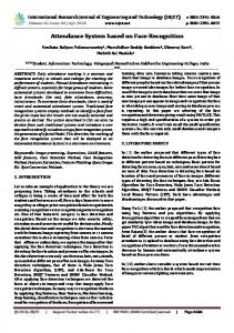
Video images were collected using a Photo3S high resolution camera onboard of an Aeryon Scout quad-copter UAS (Aeryon, 2013). The Scout flew over York University, up to approximately 40 meters above the ground level (AGL), while the gyro-stabilized camera focused on buildings, walkways, and trees (Figure 1a). The imagery was downsampled to 1 megapixel to enable fast image processing. The 3D virtual building model of York University’s Keele campus (Armenakis and Sohn, 2009) was used as the known 3D map environment (Figure 1b). The model consists of photorealistic TIN reconstructions of buildings, trees, and terrain, generated from building footprint vector data, Digital Surface Model (DSM) with 0.75 m ground spacing, corresponding orthophotos at 0.15 m spatial resolution and terrestrial images. The 3D building model was further refined with airborne lidar data having a point density of 1.9 points per square meter (Corral-Soto et al., 2012). This 3D CAD model serves two purposes in the proposed approach. First, it provides the necessary level of detail of linear features (vertical and horizontal lines) for feature matching. Second, it provides ground control points to achieve photogrammetrically sub-meter accuracies of the positional elements of the exterior orientation. The geometric accuracy of the building models is in the order of 10 to 20 cm.
(b)
Figure 1. (a) The Aeryon Scout UAS GPS flight path around the Lassonde Building shown in an orthophoto, and (b) The 3D York University Campus Model.
1118
Novem b er 2 014
PHOTOGRAMMETRIC ENGINEERING & REMOTE SENSING
Methodology
Overview of Geometric Hashing The geometric hashing algorithm is divided into two stages, the preprocessing phase and the recognition phase. The flow chart of the process is provided in Figure 2, and the algorithm is summarized as follows (Wolfson and Rigoutsos, 1997). In the subsequent sections the algorithm is applied to real data collected by the Aeryon Scout UAS.
Recognition Phase When presented with an input image, do the following: 1. Extract point features from the image. 2. Choose an arbitrary basis from the extracted features: two points when assuming objects undergo similarity transformation, three points for affine transformation, or four points for projective transformation. 3. Compute the coordinates of the remaining feature points in a canonical reference system Oxy defined by the selected basis. 4. Suitably quantize each such coordinate and access the appropriate hash table bin; for every entry found there, cast a vote for the model/basis combination. Potential matches correspond to the model/basis combinations that receive more than a certain number of votes. 5. For each potential match, recover the transformation (camera pose) that results in the best least-squares match between all corresponding feature pairs. 6. Transform the features of the model according to the recovered transformation and verify them against the input image features. If the verification fails, return to Step 2 using a different image basis pair. If the verification passes, process the next image.
The proposed strategy to finding correspondence between the 3D building model and the UAS’s video imagery is to generate a database of images of the building model, referred to in this work as synthetic images, captured from various vantage points. Then, extract features from the current FPV video frame and match them with the model features that are visible in the synthetic images. That is, based on the image from the UAS video camera, georeferenced buildings that appear in the image are retrieved from the database, and then the retrieved buildings are used as ground control to determine the camera position and orientation. The main challenge and focus of this work, is retrieving the correct building from the database, which is essentially matching features extracted from an image with features in a database. This process is divided into two components: (a) the preprocessing phase generates the database, and (b) the recognition phase processes incoming images. Geometric hashing provides only the search engine portion of an object recognition system; the representation and extraction of the features are crucial inputs to geometric hashing. Deciding on the features to match depends on the available models and collected data.
Figure 2. Flow chart for the geometric hashing algorithm (Lamdan and Wolfson, 1989). Preprocessing Phase For each model M (a synthetic image in this case), do the following: 1. Extract the model’s point features. 2. For each basis of two point features (assuming objects undergo similarity transformations), three point features (for affine transformation), or four point features (for projective transformation), do the following: a) Compute the coordinates (x', y') of the remaining features in a canonical reference frame defined by the basis. PHOTOGRAMMETRIC ENGINEERING & REMOTE SENSING
b) After proper quantization, use the coordinates (xq',yq') as an index into a 2D hash table data structure and insert the information (M, basis), namely the model number and the basis used to determine (xq',yq'), into the corresponding hash table bin.
Feature Selection The textures of the building models have little correlation with the UAS’s FPV imagery because of changes in illumination and weather conditions, along with the presence of shadows. Further, the colors of buildings may change with time, for example when roofs are repaired or walls are painted. However, the shape of the building remains constant in time and is more suitable for matching. Thus, this work focuses towards matching geometric features (points, lines, polygons, etc.), as opposed to intensity-based features such as using SIFT (Lowe, 1999) and SURF (Bay et al., 2008) algorithms. This is convenient as 3D models generally provide a database of georeferenced vertices (points), edges (lines), and faces (polygons). Extracting feature points with a corner detector, such as Harris corners (Harris and Stephens, 1988), would yield many unwanted points from objects surrounding the building such as trees for instance which are not included in the model. To consider matching polygons, a robust solution is required that could handle a variety of noise, occlusions, and incomplete or unclosed figures. Such a method would increase the complexity and run-time of the system. Matching silhouettes has been proposed (Latecki et al., 2000), but are limited as they ignore internal contours and are difficult to extract from real images. More promising approaches are the matching of edges based, for example, on the Hausdorff distance (Huttenlocher et al., 1993; Valtkamp and Hagedoorn, 1999) or the Distance Transform (Gavrilla et al., 1999). A drawback for this application is that the method does not return correspondence (Belongie et al., 2002). Linear features were chosen to establish correspondence between the model and the image. Line matching approaches are divided into algorithms that match individual line segments and algorithms that match groups of line segments. Matching single lines is based on geometric properties, such as orientation, length, and extent of overlap, and thus lines contain richer semantic information than point features. Matching groups of lines takes away the ambiguity involved by providing both pattern associations and geometric
Nove mber 2014
1119
information. Graph-matching is a common approach, as graphs capture relationships such as left of and right of, and topological connectedness (Baillard et al., 1999). The chosen linear feature, referred to in this work as the Vertical Line Feature, consists of two corners connected by a vertical line. In agreement with Cham et al. (2010), vertical line features were chosen over horizontal line features because they commonly appear in structured environments, and the gyro-stabilized camera enables vertical lines to be identified efficiently and reliably, as vertical lines in the object space are highly probable to be vertical or close to in the image space.
Vertical Lines are extracted in a similar manner, using Top Right and Bottom Right corners. Initially, the correspondence is established solely on Left and Right Vertical lines. Top and Bottom Horizontal Lines Features can be extracted in a similar fashion only if an insufficient number of corresponding Vertical Line Features is found, as this will increase the processing time. Alternatively, Leung et al. (2008) use vanishing point analysis to extract horizontal and vertical lines from an image; however they demonstrate that this requires a lot of processing power to realize a real-time system.
Feature Extraction The following process was developed to identify corresponding features: First, corners are extracted from the Canny edge image and classified according to their orientation into one of the following types: (a) Top Left, (b) Bottom Left, (c) Top Right, or (d) Bottom Right. For example, the Top Left Corner Templates in Figure 3a are used to classify top left corners using 2D cross-correlation (Lewis, 1995). Rotated versions of these templates are used to classify the remaining corner types in a similar fashion, i.e., the Top Right Corner Templates are obtained by rotating the Top Left Corner Templates clockwise by 90 degrees.
Model-to-Image Matching with Geometric Hashing
(a)
(b)
(c)
Figure 3. (a) Top Left Corner templates, (b) Left Vertical Line Feature, and (c) Right Vertical Line Feature. The extracted corners are used to construct Left and Right Vertical Lines, shown in Figures 3a and 3b, respectively. Specifically, Left Vertical Lines meet the following criteria: 1. The Top Left Corner should be higher in the image than the Bottom Left Corner. 2. A Left Vertical Line Feature is a continuous line of pixels that connect a Top Left Corner to a Bottom Left Corner. The very simple and efficient line extraction techniques presented by Smith et al. (2006), such the length, midpoint, quarter point and Bresenham walk checks, were used. 3. Given the roll and pitch of camera are kept approximately stable by the gimbal system mount due to the wind acting on the UAS, the slope of the line should be within a tolerable range of the vertical defined by the image’s vertical axes. The camera is pitching downwards viewing the building, while the roll angle is kept close to zero due to the gimbal mount. All the combinations of Top Left Corners and Bottom Left Corners are tested against the various conditions. If a Top Left Corner and Bottom Left Corner do not meet a condition, the pair of points is discarded and the next combination of points is tested. Tests are performed in increasing order according to computational complexity to increase efficiency. Right
1120
Novem b er 2 014
As previously mentioned, the geometric hashing process consists of: the preprocessing phase that generates the database, and the recognition phase that processes the incoming images. The Preprocessing Phase In a preprocessing stage, a database of the Vertical Line Features extracted from the buildings on York University’s Keele Campus was created to efficiently recognize Vertical Line Features extracted from UAS images. Synthetic Images of the 3D Model To generate the database of synthetic images, 3D building models are loaded into GoogleEarth™ Sketchup, a 3D computer graphics software product (GE SketchUp, 2013). For each building model, such as the Lassonde Building Model shown in Figure 4a, the normal vectors η of the building TIN faces are averaged to ηave, to determine the prominent directions faced by the building walls. Each prominent normal direction represents a group, and each face is then assigned to the group whose average normal is closest its normal. For example, the normals of the faces of the Lassonde building separated into four prominent normal directions: North (0° ≤ ηave