Dual Damascene BEOL processing using multilevel step and flash imprint lithography Brook Chao1, Frank Palmieri1, Wei-Lun Jen1, D. Hale McMichael1, C. Grant Willson1, Jordan Owens2, Rich Berger2, Ken Sotoodeh2, Bruce Wilks2, Joseph Pham2, Ronald Carpio2, Ed LaBelle2, and Jeff Wetzel2, 1
The University of Texas at Austin, Austin, TX 78712 ATDF, Inc., 2706 Montopolis Dr., Austin, TX 78741
2
Brook H. Chao: email:
[email protected], Tel: 512-471-6364, Fax: 512-471-7222
Abstract Step and Flash Imprint Lithography (S-FIL®) in conjunction with Sacrificial Imprint Materials (SIM) is capable of simultaneously patterning two levels of interconnect structures, which provides a low cost BEOL process. This paper describes the integration of SFIL into an industry standard Cu/low k dual damascene process that is being practiced in the ATDF at Sematech in Austin. The pattern transferring RIE process is the most critical step and was extensively explored in this study. In addition to successful process development, the results provide useful insight into the optimal design of multilevel templates which must take into account the characteristics of both the imaging material and the dielectric layer. The template used in this study incorporates both the via and trench levels of an M2 (Metal 2) test vehicle that incorporates via chains with varying via dimensions, Kelvin test structures, serpentines, etc. The smallest vias on the template are 120nm vias with an aspect ratio of 2.0 and the smallest dense lines are 125nm/175nm with an aspect ratio of 2.9. Two inter-level dielectrics (ILD), Coral® and Black Diamond® were studied. No trench etch stop was incorporated in the ILD film stack. A multi-step, in-situ reactive ion etching (RIE) scheme was developed that achieves faithful pattern transfer from the sacrificial imprint material into the underlying low k ILD with surprisingly wide process latitude. This multi-step scheme includes the following etch steps: a residual layer open, a via etch, a trench descum, a trench etch, and an SIM removal ash. Among these steps, the trench etch was found to be the most challenging to develop and it holds the key to producing high aspect ratio dual damascene features. An etching chemistry based on two fluorocarbon gases, CF4 and C4F8, was found to be very effective in delivering the desired etch profiles with optimal sidewall angle, minimal facet formation. A set of statistically designed experiments (DOE) based on this chemistry was conducted to assist the trench etch process development. The optimized etch process can be exploited to provide substantial size reduction and/or increased aspect ratio relative to the template. In this way structures with final critical dimensions of 95nm in vias with aspect ratio of 3.0 and 60nm/240nm in dense lines with aspect ratio of 4.3 were demonstrated with wide process latitude. This enables manufacturing of the template at larger dimensions, which simplifies both fabrication and inspection. The successful development of the dual damascene RIE process at the second metal (M2) level was demonstrated in a mixed and matched build with an ATDF standard first layer metal (M1) process. The M1 dielectric was TEOS and was patterned by 248nm lithography. The M2 and Via 2 levels used Coral as interlayer dielectric (ILD) and both levels were patterned simultaneously by S-FIL using Molecular Imprint Imprio 55 and Imprio 100 imprint tools. This electrical test vehicle provided solid evidence that S-FIL is fully compatible with industry standard dual damascene process. Keywords: nanoimprint lithography, SFIL, dual damascene, interconnect, SIM 1. Introduction
1
The state of the art back end of line (BEOL) employs Cu interconnects and low dielectric constant (low k) ILD to reduce signal delay, cross talk, and power dissipation. These Cu interconnects are made with the dual damascene process and comprise via and trench structures. Vias are interconnects that transmit signals between adjacent wiring levels and trenches are line structures which distribute signals within each interconnect level. The conventional dual damascene processing requires separate lithography and etching steps to pattern the vias and trenches prior to subsequent metallization and chemical mechanical polishing (CMP) steps to complete each of the wiring levels. The process has become increasingly complex and costly because as many as ten or more wiring levels are needed in advanced chip designs. Step and Flash Imprint Lithography (S-FIL) in conjunction with a multi-level template provides a brand new approach to dual damascene processing, which is expected to significantly reduce the number of processing steps required to build the interconnect structures1 and thereby lower the wafer cost2. Schmid1 showed that one imprint lithography step can produce the same dual damascene patterns as two photolithography steps by virtue of a multi-level template on which both via and trench features are incorporated. The purpose of the present paper is to demonstrate that this new processing technique provides a high yield and low cost solution to the fabrication of BEOL interconnects. 2. Experiment Successful integration of multi-level S-FIL into the dual damascene process requires several processing ingredients among which imprint templates with multi-level interconnect features, an imprint tool with overlay capability and BEOL processing and qualification capability are the most essential elements. Film stack and test structures M2 dielectrics Low-k Coral ( k=2.85 ) No trench etch stop Cap layer SiCN ( k=4.7 )
M2 litho
Multilevel S-FIL M1 litho
M1 dielectrics CVD SiO2
Photolithography
(a)
Via ViaChains Chains
Isolated IsolatedLines Lines
Dense DenseLines Lines Dummy lines
IN
OUT
Comb 2
OUT
OUT
Serp/Comb Serp/Comb
Comb Comb
Serp Serp
IN
IN
Serp IN
Comb Serp OUT
Comb
Comb 1
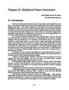
(b) Fig 1: Diagram of (a) film stack and a via chain test structure and (b) test structures
2
Fig 1 (a) shows the film stack used in this project. The M2 level patterning was done with multilevel S-FIL and mixed and matched with conventional photolithography at M1 level. The M2 ILD material is Coral and the cap layer material is SiCN. Pattern transfer etching development was also conducted using Black Diamond as the M2 ILD. No trench etch stop layer is incorporated in the process, which improves the dielectric constant of the stack. The trench endpoint is strictly time controlled but has ample process latitude. In order to enable the qualification of the processes using electrical testing, a host of test structures of various sizes were incorporated. These test structures include via chains, Kelvin arrays (single vias), various line structures and interdigitated serpentines, as shown in Fig 1 (b). Each test structure was printed at several dimensions, generally ranging from 120 nm to 2 μm. Multi-level template The template used in this study incorporates both the via and trench features of the M2 test vehicle. The active area on each template is 25 mm by 25 mm and includes four duplicates of the electrical test patterns. Unused areas between test structures are filled with dummy features to maintain a constant pattern density for improved CMP uniformity. The multilevel templates for this 3 project were purchased from Toppan Photomask. Table 1 shows the critical dimensions (CD) of the dual damascene features on the multi-level template and Fig 2 shows the result of the microscopic analyses. Table 1: Multi-level template features (Data courtesy of Toppan Printing Co., Ltd) Features Vias Lines
Nominal CD 120 nm 125 nm
Height 239.78 nm (with residual Cr) 361.15 nm
(a)
(b)
Fig 2: Multi-level template (a) top-down SEM image of 120 nm vias on lines and (b) AFM image of a via chain of 1 um vias. (Images courtesy of Toppan Printing Co., Ltd)
3. Results and Discussion S-FIL Processing The S-FIL process has been reported in previous articles and is only briefly described here.4,5 Figure 3 shows the process sequence used for a multi-level pattern imprinting. A low-viscosity, photopolymerizable imprint liquid was first dispensed onto the substrate. A quartz template with multi-level structures was then brought into contact with the imprint liquid at room temperature and low imprint pressure, and allowed to fill the contours of the template. Once the filling was complete, ultra-violet irradiation was used to polymerize the imprint liquid into a solid film, and finally the template was removed from the solidified imprint monomer. This hardened film retains
3
a negative replica of the quartz template pattern, and it is ready for pattern transfer etches. The imprinting was accomplished with Imprio R55 and Imprio 100 tools from Moelcular Imprints, Inc.
Steps
Components Template Release treatment Monomer droplet
1.Monomer Dispense
Substrate film stack
Spreading
2. Spread and Fill
UV radiation
3. UV Cure
Crosslinked film
4. Separate
Figure 3: Multi-level SFIL process Fig 4 shows 3D patterns made by the multi-level S-FIL process. Both via and trench structures were patterned into the sacrificial imprint material. The via structures shown in these SEM images resulted from via structures on the template targeted for 120 nm CD and resulted in imprinted via patterns of 97 nm. Based on metrology of SEM images of the imprinted patterns, the via sizes on vary between 95 nm and 120 nm from place to place in the patterns for the vias targeted for 120 nm on the template. This consistent variance very likely results from variation in the template CD. The imprinted via height is approximately 224 nm.
(a)
(b)
(c)
Fig 4: Imprints of the multi-level template showing 97 nm via structures . An important characteristic of multi-level S-FIL is that the three dimensional nature of the imprints imposes certain yield and performance issues for the final circuits, which will be discussed in the next section.
4
Clamping Vacuum
Back Pressure
Clamping Vacuum
RLT Wafer
Fig 5: (a) Residual layer thickness (RLT) and (b) imprinting process with template curvature Uniformity of the residual layer thickness (RLT) shown in Fig 5 (a) is an important process requirement. The pressure provided to the back of template as shown in Fig 5 (b) is the one variable that can influence this parameter. Fig 6 shows variation of RLT across an imprinted field measured nondestructively using spectroscopic ellipsometry. Higher back pressure (0.075 Bar) generates concave imprints (convex template), and lower back pressure (0.04 Bar) generates convex imprints (concave template). The convex template condition is desirable for higher throughput and minimal air entrapment. Optimizing this curvature by varying the back pressure and adjusting the placement of the drop of imprint liquid to compensate for the spatial variation of the feature density (Fig 7) provided a RLT uniformity of 8.8 nm 1 σ.
RLT (nm)
Back pressure = 0.075 Bar RLT range = -56.8 nm (center to edge) RLT uniformity = 17.7 nm 1 σ
Back pressure = 0.04 Bar RLT range = +40.9 nm (center to edge) RLT uniformity = 13.4 nm 1 σ
Fig 6: Varying the global curvature of the residual layer by varying back pressure:
5
(a)
(b)
Fig 7: (a) Optimized Drop pattern and (b) corresponding RLT contour (uniformity = 8.8 nm 1 σ) We maintained a slightly convex template condition because, during the liquid spread step of the imprinting process, a slightly convex template facilitates capillary flow of the liquid from the center to the edge of the die and thereby significantly reduce the required spread time (higher throughput) and prevents air to be entrapped (higher yield). Pattern transfer etching After successful development of an S-FIL process generating very planar multi-level imprints, an etching step is required to transfer the dual damascene patterns from the SIM into the underlying low k dielectrics. Fig 8 (a) shows the basic concept of the pattern transfer etching step. Ideally, this step begins with fully planar multi-level imprints and the dual damascene patterns are then transferred into the M2 dielectrics faithfully.
Imprint Resist M2 Dielectrics Diffusion Barrier M1 Dielectrics
Metallization/CMP
Metallization/CMP
Metallization/CMP
(a)
(b)
(c)
Fig 8: Multi-level pattern transfer: (a) concept, (b) challenge regarding etch artifacts, and (b) challenge regard imprint uniformity However, two major challenges associated with the etching step were identified during the process development. These are shown in Fig 8 (b) and (c) and described as the following:
6
1. Etch artifacts. In order to achieve the anisotrpic etching required for patterning vias with vertical sidewalls, highly polymerizing etching chemistry was employed . Such chemistry generally renders a very rough top surface on the resist due to concurrent etch residue deposition and aggressive ion bombardment. For photolithography, the via and trench structures are patterned separately. The resist over the protected area is never consumed during pattern transfer and therefore the undesirable etch artifacts do not affect the etched features. For multi-level S-FIL, however, the resist at the trench level protects the dielectrics when the via structures are being transferred, but is consumed subsequently in order to transfer the trench patterns. Etch artifacts that accumulate on the resist are transferred into the dielectric during trench etch as shown in Fig 8 (b). These etch artifacts can substantially compromise the performance and reliability of interconnects 2. Imprint non-uniformity. The drawbacks of direct pattern transfer from non-uniform imprints can be seen in Fig 8 (c). The interconnect line height may vary due to the imprint non-uniformity causing variance in line resistance. The slowest vias, where the initial RLT is the thickest, may not receive sufficient etching to penetrate the cap layer causing low via yield. Therefore, an etching process which tolerates a certain budget of imprint nonuniformity is essential in integrating multi-level S-FIL. An analysis of our etch process, described below, shows a tolerance of 16nm 1σ. We achieved a variance of less than 9nm 1σ In-situ multi-step etching scheme An in-situ multi-step etching scheme has been developed in order to achieve faithful pattern transfer of multi-level imprints and meeting the etching challenges identified in the previous section. It is fully compatible with standard BEOL etching chemistry and tool set. Each step of the multi-step scheme is detailed as the following and the experimental results are shown in the diagrams and figures in Table 2. The etching was carried out on a TEL XXXX!!!! 1. Residual breakthrough. The residual breakthrough etch step opens the thin residual layer at the bottom of the via imprints. H2/N2 chemistry was used in this step because it has very high selectivity of SIM over Coral ILD. The high selectivity eliminates the die-todie variation of the residual layer thickness. 2. Via transfer. C4F8/Ar/N2 chemistry was used in via transfer etch. When properly tuned, this chemistry renders nearly vertical sidewalls in even minute features. However, this chemistry is highly polymerizing and incorporates aggressive ion bombardment. The side effect is very rough top surface on the resist, substantial surface pitting and potential micro-trenching at the line structures. The via transfer step is terminated well before these undesirable etch artifacts are transferred into the ILD. 3. Trench descum. The trench descum step prevents the roughness and micro-trenching from the anisotropic via etch from being transferred into the Coral ILD. H2/N2 chemistry is used for this etch step An additional advantage of this etch step is that any nonuniformity in the trench patterns that originated from the imprints is removed as the trench pattern transfer now starts on the planaried ILD surface. 4. Trench transfer. The trench transfer step of must not only transfer the trench pattern but also maintain the fidelity of the via pattern. For the via first scheme of dual damascene process using microlithography, the via is usually filled and protected by BARC (bottom anti-reflective coating). BARC protects the via profile already defined in via etch step and also reduces the facet formation by pinning the facet during the trench etch. However, for step and flash imprint lithography, the via pattern is exposed to RIE during trench transfer without the protection of BARC. Therefore, the etch chemistry needs to be carefully tuned to render trench transfer with good fidelity and also maintain the via pattern. We have
7
found the etching chemistry based on a C4F8/ CF4 mixture is very effective in meeting these requirements simultaneously. 5. Ash. H2/N2 chemistry is used to strip the remaining SIM without oxidizing the exposed M1 Cu. The advantage of the multi-step etch scheme are the following: 1. 2. 3. 4. 5.
Full compatibility with BEOL etch chemistry and commercial imprint resist High tolerance of imprint uniformity (16 nm 1σ) Precise control of interconnect line resistance Ideal feature profile and minimal etch artifacts Wide process latitude (see below)
8
Table 2: In-situ multi-step etching scheme
Imprint Resist M2 Dielectrics Diffusion Barrier M1 Dielectrics
Etching Steps
SEM Images
Diagrams
Cross-sections
3D Imprint
Residual Open
Via Transfer
Trench Descum
Trench Transfer
Ash
9
Tilt Shots
RIE controlled CD shrink The multi-step etch scheme has proven effective for faithful pattern transfer, but we have found that this technique offers a unique advantage of controllable CD shrink through the via etch step. By changing the etch chemistry of the via etch step, the FCD (final critical dimensions) of the dual damascene features can be deliberately controlled and shrunk. Table 3 shows the original imprint feature and the various versions of the etched features. Table 3: RIE controlled CD shrink
120nm Via RCD (Imprinted)
105nm Via FCD (Etched)
95nm Via FCD (Etched)
70nm Via FCD (Etched)
55nm Via FCD (Etched)
38nm Via Bottom FCD (Etched)
While the original imprint was a dual damascene feature with 120nm via, the final sizes of the etched via range from 105 nm to as small as 38 nm. The CD shrink shown in this table did not occur haphazardly. It can be correlated to the etch profile during via etch step and therefore controlled by the etching chemistry used in this step. The capability of adjusting critical dimensions through etching chemistry can relax stringent requirements for the fabrication of 1X templates and may even open doors to extending the patterning capability beyond the limits of template fabrication. Process latitude In the multi-step etching scheme, the multi-level pattern transfer is consists of five etching steps. Each step focuses on meeting specific etching requirements and tailoring precise feature profiles. The step-wise scheme is run in a single chamber and offers tremendous process latitude and high throughput. Table 4 shows the process latitude of the multi-step etching scheme. Varying power and pressure over wide delivers nearly identical etched feature profiles.
10
Table 4: Process latitude of the multi-step etching scheme
45 mT / 300 W 80 mT / 700 W 45 mT / 700 W 75 mT / 400 W 103 nm Via (AR=2.88) 95 nm Via (AR=3.04) 99 nm Via (AR=2.77) 123 nm Via (AR=2.32) 77 nm Lines (AR=3.81) 67 nm Lines (AR=3.63) 75 nm Lines (AR=3.64) 73 nm Lines (AR=3.37)
Electrical testing E-test process optimization After the etching process, the wafer receives standard BEOL metallization processing. The connectivity of these interconnects is subsequently verified by the electrical testing performed on the via chain structures. Fig 9 shows the pre-CMP SEM image of the dual damascene feature made with the E-test process.
Cu (M2) Ta Coral Cu (M1) Fig 9: Pre-CMP dual damascene feature of E-test process 115nm CD
11
Formatted: English (U.S.)
Cumulative Probability (%)
100 80 60 40 Via #1 Via #2 Via #3
20 0 2
4
6
8
10
12
14
16
Kelvin Via Resistance (Ohm) Fig 10: Kelvin via resistance of E-test process (120 nm template CD / 115 nm final CD, as shown in Fig 9) Fig 10 shows the Kelvin via resistance of the dual damascene structures made by the E-test process. Kelvin vias are single contact via structures used for basic qualification of the via process. From fig 10, 95.2% yield has been achieved for the 120 nm Kelvin via structures tested. Further E-test analysis showed that the 120 nm via chain yield was inconsistent for this process due to insufficient breakthrough of the cap layer. The SiCN cap layer incorporated in the film stack is a very etch resistant to fluoro carbon based etching chemistry. The Coral to SiCN selectivity of the C4F8/CF4 mixtures tested ranges from 7 to 10. To etch through the cap layer at the via bottom is additionally challenging due not only to the etch resistance of SiCN but to the reduced etch rate at very small vias owing to etch bias. Processing high aspect ratio vias such as those shown in figure 9 requires advanced CVD tools and ethc tools. The ATDF is equipped to process such structures and clear the SiCN barrier layer on 300mm wafers, but the 200mm tool set has limitations and we can only print 200mm wafers on our current Imprio tools. Therefore we sought to improve the via chain yield using other alternatives. We intentionally faceted the via structure by adjusting the trench etch chemistry which greatly enhances the etch rate of the SiCN cap. Fig 11 shows the dual damascene feature made by this tailored process. Again, this faceting was done intentionally to accommodate the 200mm tool limitations at the ATDF. This accommodation enabled reliably opening the barrier layer and provided excellent connectivity results in the 1000 contact via chains.
12
Fig 11: Dual damascene feature intentionally faceted for processing in the 200 mm tool set
Cumulative Probability (%)
Fig 12 shows the resistance of 1000 contact via chain with via template CD of 120 nm and final bottom CD of 82 to 115 nm. For all chains tested, the resistance is quite consistent from site to site in a die and across the wafer. The overall yield of these chains is as high as 96.83%, which is equivalent to individual contact yield of 99.9968%. 100 80 Chain #1 Chain #2 Chain #3 Chain #4 Chain #5 Chain #6
60 40 20 0 0
2
4
6
8
10
12
14
16
Via Chain Resistance (Ohm per contact)
Fig 12: 1000 contact via chain resistance an adaptive E-test process to 200 mm tool set (120 nm template CD / 82 nm final bottom CD)
4. Conclusion We have completed the demonstration of a Cu/low-k BEOL dual damascene process using multilevel Step and Flash Imprint Lithography. A new approach to pattern transfer etching was established to perform the etching in a step-wise, in situ fashion. The in-situ multi-step etching scheme offers the advantages of high tolerance of imprint uniformity, ideal feature profile and minimal etch artifacts. The study shows that the multi-step etch scheme also provides ability to perform a controlled shrink of the via size and offers surprisingly wide process latitude. High electrical test yields were obtained for the via chains which demonstrates the viability of Step and Flash Imprint Lithography candidate for integration into BEOL dual damascene processing. Acknowledgements
13
We would like to thank the DARPA - AP2C program and Applied Materials for funding. The authors also thank Kang Luo, John Maltabes, Joseph Perez and Steven Ma of Molecular Imprints, Melissa Freeman, Britton Birmingham and PCL lab staff of ATDF for help with various aspects of this work. The authors would also like to thank ATDF, Inc. and International Sematech for providing access to their copper dual damascene processing and characterization facilities. References 1. Schmid, G.M., M. Stewart, J.T. Wetzel, F.L. Palmieri, J. Hao, Y. Nishimura, K. Jen, E.K. Kim, D.J. Resnick, J.A. Liddle, and C.G. Willson, "Implementation of an imprint damascene process for interconnect fabrication”. Journal of Vacuum Science & Technology, B: Microelectronics and Nanometer Structures--Processing, Measurement, and Phenomena (2006), 24(3), 1283-1291 2. Litt, L.C., “Cost Analysis of Nanoimprint Lithography”. Nanoimprint and Nanoprint Technology Plenary Paper, November 2006. 3. MacDonald, S., Hughes, G., Stewart, M., Palmieri, F., Willson, C.G., Design and fabrication of highly complex topographic nanoimprint template for dual Damascene full 3-D imprinting. Proceedings of SPIE-The International Society for Optical Engineering (2005), 5992(Pt. 1, 25th Annual BACUS Symposium on Photomask Technology, 2005), 59922F/1-59922F/9. 4. Colburn, M., S. Johnson, M. Stewart, S. Damle, T.C. Bailey, B. Choi, M. Wedlake, T. Michaelson, S.V. Sreenivasan, J. Ekerdt, and C.G. Willson, "Step and flash imprint lithography: a new approach to high-resolution patterning". Proceedings of SPIE-The International Society for Optical Engineering, 1999. 3676(Pt. 1, Emerging Lithographic Technologies III): p. 379-389. 5. Resnick, D.J., W.J. Dauksher, D.P. Mancini, K.J. Nordquist, T.C. Bailey, S.C. Johnson, N.A. Stacey, J.G. Ekerdt, C.G. Willson, S.V. Sreenivasan, and N.E. Schumaker, "Imprint lithography: lab curiosity or the real NGL". Proceedings of SPIE-The International Society for Optical Engineering, 2003. 5037(Pt. 1, Emerging Lithographic Technologies VII): p. 12-23.
14