Distribution for Global Interconnects in a Heterogeneous System- on-a-Chip', IEEE Trans. VLSI Systems, Dec. 2000. [12] H. Youssef, E. Shragowitz, L.C. Bening, ...
Multi-objective Circuit Partitioning for Cutsize and Path-Based Delay Minimization Cristinel Ababei*
Navaratnasothie Selvakkumaran**
Kia Bazargan*
George Karypis**
* Department of Electrical and Computer Engineering University of Minnesota, 200 Union St. SE Minneapolis, MN 55455 {ababei,kia}@ece.umn.edu
** Department of Computer Science University of Minnesota, 200 Union St. SE Minneapolis, MN 55455 {selva,karypis}@cs.umn.edu
Abstract – In this paper we present multi-objective hMetis
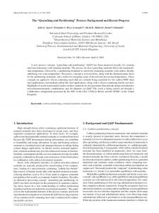
constraints while minimizing the cutsize. Gate replication in these methods can be massive. The way timing optimization is handled in timing-driven partitioning approaches, can be classified into two categories: (1) path-based timing minimization approaches and (2) net-based timing minimization approaches. Most of the previous works fall into the second category. The net-based partitioning approaches define some criticality value (e.g. slack) for each net, as a measure that indicates the degree of its contribution to the circuit delay. The partitioning process is discouraged from cutting edges with high criticality values, which is similar to minimizing the bounding box for each critical net. The drawback of the net-based techniques is that nets that lie on the same critical path are treated in the same way as when they are on different critical paths. Figure 1 shows an example of a situation in which net-based techniques fail to consider the whole path in the partitioning process. It is clear that the partitioning in Figure 1-a will result in a larger circuit delay than the one in Figure 1-b because all three cut nets belong to the same critical path.
partitioning for simultaneous cutsize and circuit delay minimization. We change the partitioning process itself by introducing a new objective function that incorporates a truly path-based delay component for the most critical paths. To avoid semi-critical paths from becoming critical, the traditional slackbased delay component is also included in the cost function. The proposed timing driven partitioning algorithm is built on top of the hMetis algorithm, which is very efficient. Simulations results show that 14% average delay improvement can be obtained. Smooth trade-off between cutsize and delay is possible in our algorithm.
1. Introduction The increase in circuit complexities and the high demand for short time-to-market products force designers to adopt divideand-conquer design methodologies. Furthermore, ever-growing performance expectations require designers to perform optimization at all levels of the design cycle. Significant contribution of interconnect to the area and delay of today’s and future chips, combined with the fact that partitioning has a great impact on the interconnect distribution, makes partitioning a very important early step during physical design. It is imperative to account for timing during the partitioning process to allow for early wire planning. In this paper we present multi-objective hMetis [4] partitioning for cutsize and circuit delay minimization. Our timing-driven optimization approach is different from previous work: we modify the objective function of the hMetis partitioning algorithm to minimize cutsize as well as circuit delay without performing any netlist alterations (e.g., buffer insertion and gate duplication), though our method can be easily modified to incorporate these techniques as well. The remainder of the paper is organized as follows. Section 2 presents previous work on timing-driven partitioning. Section 3 presents the multi-objective partitioning methodology. In Section 4, we study the algorithm to find the K most critical paths during partitioning. Simulation results are presented in Section 5. We conclude, outlining our main contribution in Section 6.
2. Previous Work In the past decade, there have been some works on timing-driven partitioning (e.g., [1], [2], [5], [6]). Most previous approaches achieve delay minimization by altering the netlist using logic replication, retiming, and buffer insertion in order to meet delay
0-7803-7607-2/02/$17.00 ©2002 IEEE
a)
b)
Figure 1 Example of a situation where net-based partitioning approaches fail to diffrentiate between partitionings with the same cutsize but different delays
We can identify a few problems for all previous timing driven partitioning approaches: (1) Unrealistic delay models are used. It is common to use the general-delay model, which considers delay 1 for all gates, delay 0 for interconnects inside a partition, and a constant delay for interconnects between partitions [1], [5], [6]. (2) Unrealistic simplifications are made. For instance, circuits are mapped to two-input gates only [1]. (3) The run times for even moderate-sized circuits are too long. In this paper, we try to eliminate the above deficiencies. We modify the objective function of the hMetis partitioning algorithm to minimize the cutsize as well as the circuit delay. We dynamically focus the timing optimization engine on the K most critical paths and use timing criticality to characterize each net that lies on the critical paths. We use the Elmore delay, along
with different wire delays at different levels of partitioning to achieve a more realistic delay model. Our interconnect delay model incorporates a statistical net-length estimation [11]. All these make our timing-driven partitioning algorithm fast and more reliable. Moreover, we do not modify the netlist, which results in no increase in the gate area of the circuit.
3. Multi Objective hMetis Partitioning: Cutsize and Delay Minimization While the goal of classic partitioning algorithms is to minimize cutsize – and hMetis performs this task very efficiently [4] – the multi-objective graph partitioning problem is much more difficult. One of the main difficulties in performing multiobjective optimization is that no single optimal solution exists. Instead, an optimal solution exists for each objective in the solution space. Furthermore, an optimal solution for one objective may require accepting a poor solution for another one. The result is that the definition of a good solution becomes ambiguous. We will adopt the formulation of a good solution as it appears in [7]: • Allow fine-tuned control of the tradeoffs of the objectives. • Generate predictable partitionings. • Provide a way to handle objectives that correspond to quantities that are of different natures (e.g., range, variance, sensitivity to changes in partitioning). In our case we want a partitioning algorithm that can minimize objective C, the number of wires cut (hence minimizing congestion at placement) and objective D, the number of times most critical paths are cut (minimizing circuit delay). However, the two objectives are dissimilar objectives, which means that optimizing C alone does not necessarily imply that D is also optimized and vice-versa. That is why we adopt a combinationbased formulation for multi-objective optimization: if C0 is the optimal solution with respect to the first objective C and D0 is the optimal solution with respect to the first objective D, then the combined objective will be a scalar combined metric Cc given by the following equation: C D (1) C c = p1 + p2 C0 D0 Where (p1, p2) is the preference vector. Minimizing equation 1 attempts to compute a partitioning such that it is not far away from any of the optimal with respect to any initial objective. A preference vector of (1,3) for example, indicates that we need to move at least three units closer to the optimal partitioning with respect to the delay objective for each unit that we move away from the optimal partitioning with respect to the cutsize objective. The preference vector can be used to traverse the distance between the optimal solution points of each objective. That results in predictable partitioning based on the preference vector as well as fine-tuned control of the tradeoff between the two objectives. The delay objective component is expressed as a combination of three factors that directly influence the delay of a circuit: the delay of the critical paths, the number of times that each critical
path has been cut, and the edge weight of all edges that lie on the critical paths. D =α
|E K |
∑ i =1
ω i ei + β
K
∑D kγ j
j
(2)
j =1
Where α and β are weighting parameters; ωi is the edge weight of edge i (derived from the edge slack); ei is either 0 or 1 depending on whether edge i is cut or not; |EK| is the number of edges that form the K paths; Dj is the current delay of the j-th critical path; kj is the number of times that the j-th critical path has been cut so far; and γ is used for even finer tuning. Equation 2 combines the advantages of the path-based method, which captures global delay information, and the advantage of the edge-based method, that can capture timing criticality of semi-critical paths without enumerating them. Parameters α and β allow us to put more emphasis on any of the two net-based and path-based components in Equation 2.
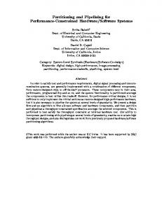
4. Path-based Timing Driven Partitioning: Choosing the K-most Critical Paths Since there are exponential number of paths in a circuit, a path-based timing-driven method has to focus only on a limited, K-most critical paths. We considered two strategies: (1) partitioning without updating of the K-most critical paths during recursive bi-section, or (2) updating the list of the K-most critical paths during recursion. In the first case we initially find the Kmost critical paths and then perform all subsequent recursive bipartioning stages trying to avoid the critical paths from being cut. The second case is motivated by the fact that the initial Kmost critical paths may not remain critical after the partitioning or placement and routing is done [12]. In this case we recalculate the K-most critical paths at each partitioning level and update the edge weights as well as path delays. In this way we can see at any partitioning level what are the current K-most critical paths and assign edge weights accordingly. Another important problem to be addressed is how to choose the value of K. On one hand, if we choose a too small K we will end up with no-timing improvement. That is because these K paths will quickly become non-critical and other previously noncritical paths will become critical. By focusing only on a small initial number of paths the optimization is diverted from the goal of timing improvement during the partitioning. On the other hand, if we choose too large a K, the run time will increase because there will be more paths that will have to be enumerated. Also, if K is too large, there will be too many edges with large weights and the search space for the partitioning algorithm will be very limited. For example, we show in Figure 2 the path delay distribution for the too_large benchmark [9]. Before partitioning, there were 81 critical paths with normalized delays in the range (0.9, 1]. After a 10-way partitioning, none of the initial critical paths was among those with normalized delay in the range (0.8, 1]. The arrow going from the right to the left in the top-right plot in Figure 2 shows this fact. The arrows oriented from the left to the right in the same plot indicate initial non-critical paths that became critical after partitioning was completed. This is similar to results obtained previously when
this situation was observed after placement and routing were done [12]. However, if we re-calculate all K-most critical paths at each partitioning level, the above case will happen less frequently. That is shown in the bottom-right plot which emphasizes the phenomenon of critical paths becoming noncritical and non-critical paths becoming critical as taking place among paths mainly with large delays (regions 1,2,3 in the right
side of Figure 2). In this way we are able to concentrate the optimization process on the “real” K most critical paths at any time at all levels because they are re-enumerated taking into account all the wire delays that were assigned (the process of assigning wire delays to all cut nets is described in Section 5.) to all cut nets during previous partitioning levels.
No. of Paths
K Paths Fixed
4500 4000 3500 3000 2500 2000 1500 1000 500 0
4
3
2
1 24 21
too_large (14781)
81/81
...0.7
K Paths Updated
4
0.7...0.8
3
0.8...0.9
2
0.9...1
1 17 20 16
Normalized Delay
Initial
K Paths Fixed
K Paths Updated
2/81 79/81 ...0.7
0.7...0.8
0.8...0.9
0.9...1
Figure 2 The path delay distribution for too_large (total number of paths is 14781) before and after partitioning, which is done with and without updating the most critical paths in region 1 (0.9, 1]
K Paths Fixed K Paths Updated Delay decrease for all paths when K paths are updated
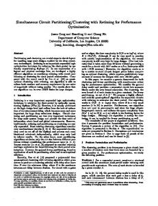
updating the list of the K-most critical paths is smaller than the one obtained without updating the list. The situation described in the example above is true for all the circuits that we tested. That is why we decide to perform recursive partitioning while dynamically updating the K-most critical paths at any partitioning level. In this way we determine a minimal number of critical paths at a certain partitioning level to become non-critical later on. In our simulations we noticed that we obtain satisfactory results if we consider as critical only the paths that lie in the region (0.95, 1] in Figure 2. In cases where the number of paths in this region exceeded 500 we retained only the first 500 paths. The enumeration path algorithm that was implemented is similar to that described in [3].
5. Simulation Setup and Results Figure 3 Number of paths distribution when K most critical paths are updated or not illustrates the delay improvement obtained when K most critical paths are updated for too_large
To further show the effect of updating the K-most critical paths during partitioning, Figure 3 shows the path distribution with respect to circuit delay in both cases. As we can see the delay obtained after partitioning performed with dynamic
In this section we describe the delay model that we use, the timing driven partitioning simulation setup and present simulation results. 5.1. Delay model Our delay model has two components. The first component is the gate delay. For all gates we consider a typical intrinsic delay that is given for a typical input transition and a typical output net capacitance. The second component is the wire delay, which we approximate using the Elmore delay model. The Elmore delay for an edge e (an edge corresponds to the
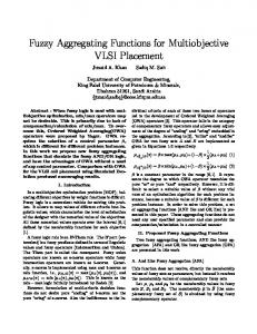
wire connecting the net source to one of its fanout sinks) is given by: C Delay (e) = Re ( e + C t ) (3) 2 where Re is the wire lumped resistance, Ce is the wire lumped capacitance, and Ct is the total lumped capacitance of the source node of each net. To compute Re and Ce we need the length of each edge. For that, we use the statistical net-length estimation method proposed in [11]. The average length of a net, connecting m cells enclosed in a rectangular area with width a and height b, is given by: a ⋅b L av ≈ (α ⋅ m γ − β ) + ( a + b) (4) a+b where α, β, and γ are fitting parameters computed in [11] as α ≈ 1.1, β ≈ 2.0, and γ ≈ 0.5. During recursive partitioning, when a net is cut, it is assigned a certain wire delay that will be used to re-compute all delays on the paths that include that net. The higher the level in which a net is cut during recursive partitioning, the greater the back-annotated wire delay has to be. In our case, any net that is cut during the first bipartitioning step (see Figure 4) is assumed to be bounded by a rectangular area which is the same as the chip area and for simplicity we consider an aspect ratio equal to 1. At the second partitioning level a and b have different values that will ensure a smaller delay than that assigned during a previous partitioning level. The delay of each net is set only the first time when it is cut. In our experiments we consider a 0.18µ copper process technology (unit length resistance r = 0.115, unit length capacitance c = 0.00015).
Net cut first time during 1st bi-partitioningÆ assign Elmore delay
1
b
2
Same Net cut during 2nd bipartitioningÆ do NOT assign Elmore delay
2
3 a
Net cut first time during 2nd bipartitioningÆ assign Elmore delay
b’ Same Net cut during 3rd bipartitioningÆ do NOT assign Elmore delay
a’
Figure 4 Illustration of the wire delay assignment to cut nets at different bipartitioning levels
5.2. Simulation Setup The simulation setup is shown in Figure 5. We start with a netlist of a circuit that was first optimized using the script.rugged in SIS [8]. Then, we perform bipartitioning using either the pure hMetis algorithm or the multi-objective method. Finally we compare the partitioning obtained in both cases in terms of cutsize and circuit delay.
Gate Netlist
Pure hMetis Bipartitioning (all edges same weight)
K Most Critical Paths Enumeration & Criticality Computation Multi Objective hMetis Bipartitioning
K Most Critical Paths Re-Enumeration & Criticality Update
Cutsize & Delay Comparison
Figure 5 Simulation setup for comparison of our proposed multiobjective hMetis partitioning algorithm to pure hMetis algorithm
5.3. Simulation Results We report simulation results for a set of combinational and sequential circuits from the ISCAS89 [9] and ITC [10] benchmark suites that are presented in Table 1. The second column in the table indicates the number of PIs and POs, followed by the number of gates in the third column. Circuit cordic misex3 X3 c6288 s15850 frisc elliptic
PI/PO No. of gates Circuit PI/PO No. of gates 23/2 881 ex1010 10/10 4898 14/14 1349 pdc 16/40 4821 135/99 1369 too_large 38/3 6961 32/32 2435 s38417 192/110 7333 39/75 4321 b21s 32/22 15604 19/16 4400 b22s 32/22 23892 130/112 4711 b17s 37/30 39390 b18s 36/22 107979 Table 1 Benchmark characteristics
The comparison results of the proposed method and pure hMetis are presented in Table 2. All results in the table are the average of 40 different runs on a Pentium dual-CPU, 1.5 GHz with 2GB of memory. For each circuit, Cutsize represents the number of all edges cut after the recursive bipartitioning. Delay indicates the maximum delay among all paths. In the net-based method, we set α=1 and β=0 in Equation 2. In the path-based method, we set α and β to non-zero values, however, only edges on the K-most critical paths are assigned a weight derived from their slack. In the “net and path-based” method, edge weights are calculated for all nets, even if they are not on the K-most critical paths. The table shows the results for 10-way partitionings. It can be seen that the proposed partitioning methodology improves delay by 14% on average. However, this is at the expense of a 10% increase in cutsize and 2.4x run-time degradation, but the runtime is still very reasonable.
Circuit Cordic misex3 X3 c6288 s15850 Frisc Elliptic ex1010 Pdc too_large s38417 b21s b22s b17s b18s Avg.
Pure hMetis 21.9 67.6 18.78 59.21 81.14 169.33 271.02 354.22 409.29 112.91 567.12 1109.62 2275.5 2606.84 1551.6 1
Delay Cutset Net- PathNet and Pure Net- Path- Net and Pure based based Path Based hMetis based based Path Based hMetis 16.53 16.42 16.41 327 275 270 278 2 63.66 59.91 61.16 543 530 669 614 5 16.65 16.9 16.65 211 270 245 261 4 55.13 55.2 56.26 182 182 215 216 31 78.85 73.61 78.93 617 699 622 671 28 150.95 168.3 150.2 838 923 910 869 34 271.02 260.25 205.25 508 547 542 619 16 338.25 304.5 331.75 1307 1260 1734 1514 21 416.99 379.24 384.5 1750 1622 2042 1847 31 103.52 111.5 97.62 2566 2459 2819 2470 20 537.75 529 527.25 198 274 232 298 18 1191 494 512.25 845 857 872 915 457 2220.75 1667 2005.75 1108 1247 1154 1136 534 2573.75 2412.25 2406.34 1780 2446 1841 1882 518 1909.5 1609.5 1333.5 1717 1730 1712 1717 860 0.96 0.87 0.86 1 1.07 1.09 1.1 1 Table 2 Comparison between our methods and pure hMetis
6. Conclusion In this paper we propose multi-objective hMetis partitioning algorithm for cutsize and circuit delay optimization. The advantages of the proposed algorithm are: (1) It is fast, thus applicable to large-sized circuits. (2) It performs better timingdriven partitioning, as it considers path delays as opposed to edge slacks. (3) It does not determine area increase because it does not use netlist alteration as previous approaches do. (4) It offers a smooth cutsize/delay tradeoff.
Acknowledgements This work was supported in part by a grant from the Office of the Vice President for Research and Dean of the Graduate School of the University of Minnesota, and in part by NSF CCR9972519, EIA-9986042, ACI-9982274, and ACI-0133464 by Army Research Office contract DA/DAAG55-98-1-0441, and by the Army High Performance Computing Research Center contract number DAAH04-95-C-0008.
References [1] J. Cong, C. Wu, ‘Global Clustering-Based Performance-Driven Circuit Partitioning’, Proc. ISPD, 2002. [2] W.E. Donath et al, ‘Timing Driven Placement Using Complete Path Delays’, Proc. ACM/IEEE DAC, 1990. [3] Y-C. Ju, R.A. Saleh, ‘Incremental Techniques for the Identification of Statically Sensitizable Critical Paths’, Proc. ACM/IEEE DAC, 1991. [4] G. Karypis, R. Aggarwal, V. Kumar, S. Shekhar, ‘Multilevel Hypergraph Partitioning: Application in VLSI domain’, Proc. ACM/IEEE DAC, June 1997. [5] J. Minami, T. Koide, S. Wakabayashi, ‘An Iterative Improvement Circuit Partitioning Algorithm under Path Delay Constraints’, IEICE Trans. Fundamentals, Dec. 2000. [6] S.-L Ou, M. Pedram, ‘Timing-driven Partitioning Using Iterative Quadratic Programming’, at http://atrak.usc.edu/~massoud/, see “Coming Attractions!”, 2001.
CPU (s) Net- Path- Net and based based Path Based 3 4 5 8 13 13 5 6 6 50 76 80 36 35 37 65 68 61 20 20 22 30 45 49 36 49 52 33 43 45 40 34 38 796 705 848 926 1250 1400 2482 2987 2991 2025 2365 3076 1.83 2.21 2.39
[7] K. Schloegel, G. Karypis, V. Kumar, ‘A New Algorithm for Multiobjective Graph Partitioning’, European Conference on Parallel Processing, 1999. [8] E.M. Sentovich, K.J. Singh, L. Lavagno, C. Moon, R. Murgai, A. Saldanha, H. Savoj, P.R. Stephan, R.K. Brayton, A. SangiovanniVincentelli, ‘SIS: A System for Sequential Circuit Synthesis’, Technical Report UCB/ERL M92/41, University of California, Berkeley, May 1992. [9] http://www.cbl.ncsu.edu [10] http://www.cad.polito.it/tools/9.html [11] P. Zarkesh-Ha, J.A. Davis, J.D. Meindl, ‘Prediction of Net-Length Distribution for Global Interconnects in a Heterogeneous Systemon-a-Chip’, IEEE Trans. VLSI Systems, Dec. 2000.
[12]
H. Youssef, E. Shragowitz, L.C. Bening, ‘Critical Path Issue in VLSI Designs’, Proc. ACM/IEEE ICCAD, 1989.