Multi Retention Level STT-RAM Cache Designs with a Dynamic Refresh Scheme Zhenyu Sun, Xiuyuan Bi, Hai (Helen) Li Polytechnic Institute of New York University, 6 Metrotech Center, Brooklyn, NY, USA
[email protected],
[email protected],
[email protected] Weng-Fai Wong, Zhong-Liang Ong National University of Singapore, 13 Computing Drive, Singapore
[email protected],
[email protected] Xiaochun Zhu, Wenqing Wu Qualcomm Incorporated, 5775 Morehouse Drive, San Diego, USA
[email protected],
[email protected] ABSTRACT Spin-transfer torque random access memory (STT-RAM) has received increasing attention because of its attractive features: good scalability, zero standby power, non-volatility and radiation hardness. The use of STT-RAM technology in the last level on-chip caches has been proposed as it minimizes cache leakage power with technology scaling down. Furthermore, the cell area of STT-RAM is only 1/9 ∼ 1/3 that of SRAM. This allows for a much larger cache with the same die footprint, improving overall system performance through reducing cache misses. However, deploying STT-RAM technology in L1 caches is challenging because of the long and power-consuming write operations. In this paper, we propose both L1 and lower level cache designs that use STT-RAM. In particular, our designs use STTRAM cells with various data retention time and write performances, made possible by different magnetic tunneling junction (MTJ) designs. For the fast STT-RAM bits with reduced data retention time, a counter controlled dynamic refresh scheme is proposed to maintain the data validity. Our dynamic scheme saves more than 80% refresh energy compared to the simple refresh scheme proposed in previous works. A L1 cache built with ultra low retention STTRAM coupled with our proposed dynamic refresh scheme can achieve 9.2% in performance improvement, and saves up to 30% of the total energy when compared to one that uses traditional SRAM. For lower level caches with relative large cache capacity, we propose a data migration scheme that moves data between portions of the cache with different retention characteristics so as to maximize the performance and power benefits. Our experiments show that on the average, our proposed multi retention level STT-RAM cache reduces 30 ∼ 70% of the total energy compared to
Permission to make digital or hard copies of all or part of this work for personal or classroom use is granted without fee provided that copies are not made or distributed for profit or commercial advantage and that copies bear this notice and the full citation on the first page. To copy otherwise, to republish, to post on servers or to redistribute to lists, requires prior specific permission and/or a fee. MICRO’11, December 3-7, 2011, Porto Alegre, Brazil Copyright 2011 ACM 978-1-4503-1053-6/11/12 ...$10.00.
previous works, while improving IPC performance for both 2-level and 3-level cache hierarchy.
Categories and Subject Descriptors B.3.2 [Memory Structures]: Design Styles—Cache memories
General Terms Design
1.
INTRODUCTION
Continuously increasing capacity as well as cell leakage cause the standby power of SRAM on-chip caches to dominate the overall power consumption of the latest microprocessors. Many circuit design and architectural solutions, such as VDD scaling [12], power-gating [15], and body-biasing [11], have been invented to reduce the standby power of caches. However, these techniques are becoming less efficient as technology continues to scale, causing the transistor’s leakage current to increase exponentially. As the alternative of SRAM, the spin-transfer torque RAM (STT-RAM) is receiving significant attention because it offers almost all the desirable features of a universal memory: the fast (read) access speed of SRAM, the high integration density of DRAM, and the nonvolatility of Flash memory. Also, its compatibility with the CMOS fabrication process and similarities in the peripheral circuitries makes the STT-RAM an easy replacement for SRAM. However, there are two major obstacles to use STT-RAM for on-chip caches, namely, its longer write latency and higher write energy. When the write access of a STT-RAM cell operates in the sub-10ns region, the magnetic tunnel junction (MTJ) resistance switching mechanism is dominated by spin precession. The required switching current rises exponentially as the MTJ switching time is reduced. As a consequence, the driving transistor’s size must increase accordingly, leading to a larger memory cell area. The lifetime of memory cell also degrades exponentially as the voltage across the oxide barrier of the MTJ increases. As a result, a 10ns programming time is widely accepted as the performance limit of STT-RAM designs, and is adopted in mainstream STT-RAM research and development [23, 18, 10, 4, 6].
• We present a detailed discussion on the tradeoff between the MTJ’s write performance and its nonvolatility. Using our macromagnetic model, we qualitatively analyze and optimize the device. • We propose a multi retention level cache hierarchy implemented entirely with STT-RAM that delivers the optimal power saving and performance improvement based on the write access patterns at each level. Our design is easier to fabricate, and has a lower die cost. • We present a novel refresh scheme that achieves much lower refresh power consumption than DRAM-style periodic refreshing. • We propose the use of a hybrid lower level STT-RAM design for cache with large capacity that simultaneously offers fast average write latency and low standby power. It has two cache partitions with different write characteristics and nonvolatility. A data migration scheme to enhance the cache response time to write accesses is also proposed. The proposed hybrid cache structure has been evaluated both in lower level cache of 2-level and 3-level cache hierarchy.
Free layer BL
WL
2. 2.1
BACKGROUND STT-RAM
MgO layer BL
WL
WL
SL High resistance state (a)
SL Low resistance state (b)
SL Equivalent circuit (c)
Figure 1: 1T1MTJ STT-RAM. (a) Anti-parallel state, (b) Parallel state, (c) Equivalent circuit. The data storage device in a STT-RAM cell is the magnetic tunnel junction (MTJ), as shown in Figure 1(a) and (b). A MTJ is composed of two ferromagnetic layers that are separated by an oxide barrier layer (e.g., MgO). The magnetization direction of one ferromagnetic layer (the reference layer) is fixed while that of the other ferromagnetic layer (the free layer) can be changed by passing a current that is polarized by the magnetization of the reference layer. When the magnetization directions of the free layer and the reference layer are parallel (anti-parallel), the MTJ is in its low (high) resistance state. The most popular STT-RAM cell design is one-transistorone-MTJ (or 1T1J) structure, where the MTJ is selected by turning on the word-line (WL) that is connected to the gate of the NMOS transistor. The MTJ is usually modeled as a current-dependent resistor in the circuit schematic, as shown in Figure 1(c). When writing “1” (high-resistance state) into the STT-RAM cell, a positive voltage is applied between the source-line (SL) and the bit-line (BL). Conversely, when writing a “0” (low resistance state) into the STT-RAM cell, a negative voltage is applied between the SL and the BL. During a read operation, a sense current is injected to generate the corresponding BL voltage VBL . The resistance state of the MTJ can be read out by comparing the VBL to a reference voltage.
3. 3.1
DESIGN MTJ Write Performance vs. Nonvolatility
The data retention time, Tstore , of a MTJ is determined by the magnetization stability energy height, ∆: Tstore =
1 ∆ e . f0
(1)
f0 is the thermal attempt frequency, which is of the order of 1GHz for storage purposes [5]. ∆ can be calculated by ∆=(
The rest of our paper is organized as follows. Section 2 introduces the technical backgrounds of STT-RAM. Section 3 describes the tradeoffs involved in MTJ nonvolatility relaxation. Section 4 proposes our multi-retention STT-RAM L1 and L2 cache structures. Section 5 discusses our experimental results. Related works are summarized in Section 6, followed by our conclusion in Section 7.
Reference layer BL
MTJ
Several proposals have been made to address the write speed and energy limitations of STT-RAM. For example, the early write termination scheme [25] mitigates the performance degradation and energy overhead by eliminating unnecessary writes to STT-RAM cells. The dual write speed scheme [23] improve the average access time of STT-RAM cache by having a fast and a slow cache partition. A classic SRAM/STT-RAM hybrid cache hierarchy with 3D stacking structure was proposed in [18]. The data retention time indicates how long data can be retained in a nonvolatile memory cell after being written. In other words, it is the unit to measure nonvolatility of a memory cell. Relaxing this nonvolatility can make the memory cells easier to be programmed, and leads to a lower write current or faster switching speed. In [17], the volume (cell area) of the MTJ device is reduced to achieve better writability by sacrificing the retention time of the STT-RAM cache cells. A simple DRAM-style refresh scheme was also proposed to maintain the correctness of the data. We note that the access patterns of L1 and lower level caches in a multicore microprocessor are different. Based on this insight, we propose STT-RAM designs with different nonvolatility and write characteristics for use in L1 and lower level caches, or even the different parts within the lower level cache so as to maximize power and performance benefits. A low power counter-controlled refresh scheme is applied to maintain the validity of the data. Compared to the existing works on STT-RAM cache designs, our work makes the following contributions:
Ku V Ms Hk V cos2 (θ) )=( ), kB T kB T
(2)
where Ms is the saturation magnetization, and Hk is the effective anisotropy field including magnetocrystalline anisotropy and shape anisotropy. θ is the initial angle between the magnetization vector and the easy axis. T is working temperature. KB is Boltzmann constant. V is the effective activation volume for the spin-transfer torque writing current. As Eq. (1) and (2) show, the data retention time of a MTJ decreases exponentially when its working temperature, T , rises. The required switching current density, JC , of a MTJ operating in different working regions can be approximated
T=300K
200
T=350K Retention time=0.67M years Retention time=6.52K years Retention time=4.27 years
100
Opt1-350K
Opt2-350K
30 150 uA switch current
20 10
(a)
0 0
0
50 100 150 200 250 300 350 400 450 500 550 600
Switching Current (uA) 1E‐9
1E‐7
1E‐5
1E‐3
1E‐1
1E+1
1E+3
1E+5
1E+7
1E+9
1E+11
STT-RAM Cell Size (F 2)
Base-350K
T=275K
Switching Time (ns)
Switcching Current (µA)
300
160.0 120.0 125 F2 cell size
80.0 40.0
(b)
0.0 0
100
200
300
Switching Current (uA)
400
500
1E+13
Switching Time (s)
Figure 2: The relationship between the switching current and the switching time of “Base” MTJ design. as [19, 16]: THERM
JC
Figure 3: (a) MTJ switching performances for different MTJ designs at 350K. (b) The minimal required STT-RAM cell size at given switching current.
3.2 Tsw 1 ln( )) (Tsw ) = JC0 (1 − ∆ τ0
π C ln( 2θ ) PREC JC (Tsw ) = JC0 + Tsw
(Tsw > 10ns)
(Tsw < 3ns).
(3a)
(3b)
PREC (T )e(−A(Tsw −TPIV )) J THERM (Tsw ) + JC sw DYN JC (Tsw ) = C (−A(Tsw −T PIV )) 1+e (3c) (10ns > Tsw > 3ns)
Here A, C and TPIV are the fitting parameters. Tsw is the switching time of MTJ resistance. JC = JCTHERM (Tsw ), JCDYN (Tsw ) or JCPREC (Tsw ) are the required switching currents at Tsw in different working regions, respectively. The switching threshold current density JC0 , which causes a spin flip in the absence of any external magnetic filed at 0K, is given by: JC0 = (
2e α )( )(tF Ms )(Hk ± Hext + 2πMs ). ~ η
(4)
Here e is the electron charge, α is the damping constant, τ0 is the relaxation time, tF is the free layer thickness, ~ is the reduced Planck’s constant, Hext is the external field, and η is the spin transfer efficiency. As proposed by [17], shrinking the cell surface area of the MTJ can reduce ∆, and consequently decreases the required switching density JC , as shown in Eq. (3a). However, such a design becomes less efficient in the fast switching region (10?
MBC WIPQ
Allocate cache block in LR-Region
Y Read@RIRQ Write@WIPQ
Decoder
Offset
Hit?
CB
LR-Region TAG DATA
Read intensive block? Y Migrate to HRRegion
N
Tag
Cache Access Y
Migrate to main memory
Main Memory
LR-Region: Low-Retention Region HR-Region: High-Retention Region
LRU: Least Recent Used CB: Counter Bits
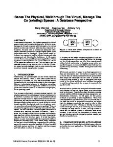
Figure 6: Hybrid lower-level cache migration policy: Flow graph (left). Diagram (right).
4.2
Lower Level Cache with Mixed High and Low Retention STT-RAM Cells
The data retention time requirement in the mainstream STT-RAM development of 4∼10 years was inherited from Flash memory designs. Although such a long data retention time can save significant standby power of on-chip caches, it also entails a long write latency (∼ 10ns), and large write energy [18]. Relaxing the nonvolatility of the STT-RAM cells in the lower level cache will improve write performance as well as save more energy. However, if further reducing retention time to µs scale, e.g., 26.5µs of our “Opt2” cell design, any refresh scheme becomes impractical for the large lower level cache. The second technique we proposed is a hybrid memory system that has both high and low retention STT-RAM portions to satisfy both the power and performance targets simultaneously. We take a 16 way lower-level cache as a case study as shown in Figure 6, way 0 of a 16-way cache is implemented with a low retention STT-RAM design (“Opt2”)) while ways 1 to 15 are implemented with the high retention STT-RAM (“Base” or “Opt1”). Write intensive blocks are primarily allocated from way 0 for a faster write response, while read intensive blocks are maintained in the other ways. Like our proposed L1 cache, counters are used in way 0 to monitor the blocks’ data retention status. However, unlike in L1 where we perform a refresh when a counter expires, here we move the data to the high retention STT-RAM ways. Figure 6 demonstrates the data migration scheme to move the data between the low and the high retention cache ways based on their write access patterns. A write intensity prediction queue (WIPQ) of 16 entries is added to record the write access history of the cache. Every entry has two parts, namely, the data address and a 16-level counter. During a read miss, the new cache block is loaded to the high-retention (HR) region (ways 1-15) following the regular LRU policy. On a write miss, the new cache block is allocated from the low-retention (LR) region (way 0), and its corresponding counter is reset to ‘0’. On a write hit, we search the WIPQ first. If the address of the write hit is already in WIPQ, the corresponding access counter is incremented by one. Note that the block corresponding to this address may be in the HR- or the LR-region of the cache. Otherwise, the hit address will be added in to the queue if any empty entry available. If the queue is full, the LRU
entry will be evicted, and replaced by the current hit address. The access counters in the WIPQ are decremented periodically, for example, every 2, 000 clock cycles, so that the entries that are in the queue for too long will be evicted. Once an access counter in a WIPQ entry reaches a preset value, NHR→LR , the data stored in the corresponding address will be swapped with a cache block in the LR-region. If the corresponding address is already in the LR-region, no further action is required. A read hit does not cause any changes to the WIPQ. Likewise, a read intensity record queue (RIRQ) with the same structure and number of entries is used to record the read hit history of the LR-region. Whenever there is a read hit to the LR-region, a new entry is added into the RIRQ. Or if a corresponding entry already exist in the RIRQ, the value of the access counter is increased by one. When the counter of a cache block Bi in the LR-region indicates the data is about to become unstable, we check to see if this cache address is read intensive by searching the RIRQ. If Bi is read intensive, it will be moved to HR-region. The cache block being replaced by Bi in the HR-region will be selected using the LRU policy. The evicted cache block will be send to main memory. If Bi is not read intensive, it will be written back to main memory. In a summary, our proposed scheme uses the WIRQ and RIRQ to dynamically classify cache blocks into three types: 1. Write intensive: The addresses of such cache blocks are kept in the WIRQ. They will be moved to the LR-region once their access counters in WIRQ reach NHR→LR ; 2. Read intensive but not write intensive: The addresses of such cache blocks are found in the RIRQ but not the WIRQ. As they approach to their data retention time limit, they will be moved to the HR-region. 3. Neither write nor read intensive: Neither WIRQ nor RIRQ has their addresses. They are kept in HR-region, or evicted from LR-region to main memory directly. Identifying a write intensive cache blocks also appeared in some previous works. In [18], they check if two successive write accesses go to the same cache block. It is highly possible that a cache block may be accessed several times within
Table 1: Simulation Platform Max issue width: 4 insts Commit width: 4 insts Load store queue size: 32 entries
Fetch width: 4 insts Dispatch width: 4 insts Write back width: 4 insts Fetch queue size: 32 insts Reorder buffer: 64 entries Max branch in pipeline: 24 Functional units: 2 ALU 2 FPU Clock cycle period: 0.5 ns Main memory: 200 cycle latency Baseline 2-level cache hierarchy Local L1 Cache: 32KB 4-way, 64B cache block; Shared L2 Cache: 4MB 16-way, 128B cache block 3-level cache hierarchy Local L1 Cache: 32KB 4-way, 64B cache block ; Local L2 Cache: 256KB 8-way, 64B cache block; Shared L3 cache: 4MB 16-way, 128B cache block
Table 2: Cache Configuration lo1 20.7 2 0.778 2 2.359 5 0.031 0.174 1.73
(L1) lo3 40.3 1 0.951 2 1.500 4 0.043 0.198 2.41
md 22 5 3.24s 0.792 2 5.370 11 0.032 0.466 1.78
very short time, and then becomes inactive. Our scheme is more accurate and effective as it monitors the read and write access histories of a cache block throughout its entire lifespan. The RIRQ ensures that read intensive cache blocks migrate from the LR-region to HR-region in a timely manner that, at the same time, also improves energy efficiency and performance.
5. SIMULATION RESULTS & DISCUSSION 5.1 Experimental Setup We modeled a 2GHz microprocessor with 4 out-of-order cores using MARSSx86 [14]. We assume two-level/threelevel cache configuration and a fixed 200-cycle main memory latency. The MESI cache coherency protocol is utilized in L1 caches to ensure consistency, and the lower level cache (L2/L3) uses a write-back policy. The parameters of our simulator can be found in Table 1. Table 2 shows the performance and energy consumptions of various designs obtained by a modified NVSim [1] simulator. All the “*-hi*”, “*-md*”, and “*-lo*” configurations use the “Base”, “Opt1”, and “Opt2” MTJ design, respectively. Note that as shown in Figure 3, they scale differently. SPICE simulations were conducted to characterize the performance and energy overheads of the counter and its control circuity. The reset energy and pushing-checking energy of SRAM counter will be included in the architecture simulation. We simulated a subset of multi-threaded workloads from the PARSEC 2.1 and the SPEC2006 benchmark suites so as to cover a wider spectrum of read/write and cache miss characteristics. We simulated 500 million instructions of each benchmark after their initialization. We compared the performance (in terms of instruction per cycle, IPC) and the energy consumption of different configurations for both 2- and 3-level hybrid cache hierarchies. We used the conventional all SRAM cache design as the baseline. Our simulation shows that the optimal STT-RAM cache configuration for 2-level cache hierarchy is the combination of (a) a L1 cache of the “L1-lo2” design, and (b) a hybrid L2 cache of using the “L2-lo” in the LR-region and “L2-md2” in the HR-region. The optimal STT cache configuration for 3-level cache hierarchy includes (a) a L1 cache of the “L1-lo2” design, (b) a hybrid L2 cache of using the “L2-
256KB (L2) md1 22 5 3.24s 2.118 5 6.415 13 0.083 0.932 14.24
hi 23 10 4.27yr 0.802 2 10.378 21 0.083 0.958 1.82
SRAM 125 / / 4.273 9 3.603 8 0.197 0.119 4107
lo 20.7 2 26.5µs 2.065 5 3.373 7 0.081 0.347 96.1
4MB (L2 or L3) md1 md2 md3 22 15.9 14.4 5 10 20 3.24s 2.118 1.852 1.779 5 4 4 6.415 11.203 21.144 13 23 43 0.083 0.070 0.067 0.932 1.264 2.103 104 69.1 61.2
hi 23 10 4.27yr 2.158 5 11.447 23 0.085 1.916 110
lo” in the LR-region and “L2-md1” in the HR-region and (c) a hybrid L3 cache of the “L1-lo2” design in the LR-region and “L3-md2” in the HR-region . The detailed experimental results will be shown and discussed in Sections 5.2 and 5.3.
5.2
Results for the Proposed L1 Cache Design
To evaluate the impacts of using STT-RAM in L1 cache design, we implemented the L1 cache with the different STTRAM designs listed in the L1 portion of Table 2 while leaving the SRAM L2 cache unchanged. Due to the smaller STTRAM cell size, the overall area of L1 cache is significantly reduced. The delay components of interconnect and peripheral circuits also decreased accordingly. Even considering the relatively long sensing latency, the read latency of STTRAM L1 cache is still similar, or even slightly lower than that of a SRAM L1 cache. However, the write performance of STT-RAM L1 cache is always slower than the SRAM L1 cache for all the design configurations considered. The leakage power consumption of the STT-RAM caches come from the peripheral circuits only, and is very low. The power supply to the memory cells that are not being accessed can be safely cutoff without fear of data loss until the data retention limit is reached. Figure 7 shows the IPC performance of the simulated L1 cache designs normalized to the baseline all-SRAM cache. On average, implementing the L1 cache using the “Base” (used in “L1-hi”) or “Opt1” (used in “L1-md”) STT-RAM design incurs more than 32.5% and 42.5% IPC degradation, respectively, due to the long write latency. However, the performance of the L1 caches with the low retention STT1 .4
L 1 - lo 1
L 1 - lo 2
L 1 - lo 3
L 1 -m d
L 1 -h i
1 .2
N o r m a liz e d IP C
Cell size (F 2 ) MTJ sw time (ns) Retention Time Read Lat (ns) Read Lat (cycles) Write Lat (ns) Write Lat (cycles) Read Dyn. Eng (nJ) Write Dyn. Eng (nJ) Leakage pow (mW)
SRAM 125 / / 1.113 3 1.082 3 0.075 0.059 57.7
32KB lo2 27.3 1.5 26.5µs 0.843 2 1.912 4 0.035 0.187 1.98
1 .0 0 .8 0 .6 0 .4 0 .2
c k le s s c h o b o d y tra b la c k
t fe r r e d a n im a te fr e q m in e flu i
v ip s
tio n s s w a p
m c f
e r h m m
k g o b m
b z ip 2
A v g
Figure 7: IPC comparison of various L1 cache designs. The IPC’s are normalized to all-SRAM baseline.
L 1 - lo 1
L 1 - lo 2
L 1 - lo 3
L 1 -m d
L 1 -h i
1 .2 5
L 1 e n e rg y b re a k d o w n
(a )
S R A M
N o r m a liz e d E n e r g y
2 .0 1 .8 1 .6 1 .4 1 .2 1 .0 0 .8 0 .6 0 .4 0 .2 0 .0
l e s a c k f e r r e ti m a t e m i n e v i p s t i o n s m c f m e r o b m k b z i p 2 A v g q c h o y tr g h m a p d a n fre c k s b o d s w flu i b la
1 .0 0
L 1 le a k a g e e n e r g y L 1 re a d e n e rg y L 1 w r ite e n e r g y
(b )
0 .7 5 0 .5 0 0 .2 5 0 .0 0
f r t le s c kr r e a te in e ip s n s c e m k ip 2 v g h o t r a f e n i m q m a v p t i o h m m gm o b b z A e s c d y c k b o lu id a fr s w f b la
Figure 8: (a) L1 cache overall energy comparison, (b) Break down of L1 SRAM cache energy. The energy consumptions are normalized to SRAM baseline.
rg rg a n n e
y w /o N th y w N th = 1 0 d p u s h in g rg y
1 .D R A M - s ty le r e fr e s h e n e r g y 2 .M -re fre s h e n e rg y w /o N th 3 .M -re fre s h e n e rg y w N th = 1 0
(a ) 1 2 3
0 .1
0 .0 1
1 E -3
k s e e t te o le r a c fe r r im a q m in c h o d y t n fre b id a c k s flu b la
s s v ip p tio n a s w
f r k ip 2 m c m m e o b m b z g h
g A v
w N th = 1 0 w /o N th
6
1 0
1 0
(b )
7
1 0
5
A v g
t e n e t e n e k in g s h e
M e m r is to r r e s e t n u m b e r
R e s e R e s e C h e c R e fre
ck sc h b o o le s dy tra ck flu f id e r r e an im t fre a te qm in e vi sw ap ps tio ns m hm cf m go er bm k bz ip 2
1
bl a
R e fr e s h e n e r g y n o r m a liz e d to L 1 o v e r a ll e n e r g y
RAM design significantly improves compared to that of the SRAM L1 cache: the average normalized IPC’s of ‘L1-lo1’, ‘L1-lo2’, and ‘L1-lo3’ are 0.998, 1.092, and 1.092, respectively. The performance improvement of ‘L1-lo2’ or ‘L1-lo3’ L1 cache w.r.t the baseline SRAM L1 cache comes from the shorter read latency even though its write latency is still longer, as shown in Table 2. However, L1 read accesses are far more frequent than write access in most benchmarks. In some benchmarks, for example, swaptions, the ‘L1-lo2’ or ‘L1-lo3’ design achieves a better than 20% improvement in IPC. The energy consumptions of the different L1 cache designs normalized to the baseline all-SRAM cache are summarized in Figure 8(a). The reported results includes the energy overhead of the refresh scheme and the counters, where applicable. Not surprisingly, all three low retention STT-RAM L1 cache designs achieved significant energy savings compared to the SRAM baseline. The “L1-lo3” design consumes more energy because of its larger memory cell size, and larger peripheral circuit having more leakage and dynamic power, as shown in Table 2. Figure 8 also shows that implementing the L1 cache with the “Base” (used in “L1-hi”) or “Opt1” (used in “L1-md”) STT-RAM is much less energy-efficient because (1) the MTJ switching time is longer, resulting in a higher write dynamic energy, and (2) a longer operation time due to the low IPC. Figure 8(b) shows the breakdown of L1 SRAM energy. The leakage energy occupies more than 30% of overall energy. In addition, STT-RAM has lower per bit read energy. Read frequency is around 4.8 times of write frequency on average, resulting in lower dynamic energy of STT-RAM. That’s why “L1-lo1”, “L1-lo2” and “L1-lo3” STT-RAM can save up to 30% to 40% overall energy compared to SRAM design. Figure 9(a) compares the refresh energy consumptions of the ‘L1-lo2’ L1 cache under different refresh schemes. In each group, the three bars from left to right represent the refresh energy consumptions of DRAM style refresh scheme,
Figure 9: Refresh energy comparison of the different refresh schemes.
refresh scheme without reset threshold Nth , and with Nth = 10, respectively. The refresh energy consumptions are normalized to the overall L1 energy consumptions when implementing the refresh scheme with Nth = 10. Note that the y-axis is in logarithmic scale. The energy consumption of the simple DRAM-style refresh scheme accounts for more than 20% of the overall L1 cache energy consumption on average. In some extreme cases of low write access frequency, for example, mcf, this ratio is as high as 80% because of the low dynamic cache energy consumption. The total energy consumption of our proposed refresh scheme consists of the checking and pushing, the reset, and the memory cell refresh. By accurately monitoring the lifespan of the cache line data, our refresh scheme significantly reduced the refresh energy in all the benchmarks. As we discussed in Section 4.1.2, the introduction of the reset threshold Nth can further reduce the refresh energy consumption by reducing the number of counter resets. This is confirmed in Figure 9(a) and (b). The number of counter reset operations are reduced by more than 20× on average after setting a reset threshold Nth of 10, resulting in more than 95% of the reset energy being saved. The energy consumption for the refresh scheme is very marginal, accounting for only 4.35% of the overall L1 cache energy consumption.
5.3
Evaluating the Hybrid Cache Design in 2level Cache Hierarchies
First, we evaluate the proposed hybrid cache design within L2 cache in 2-level cache hierarchies. In comparing the different L2 cache designs, we fixed the L1 cache to the ‘L1lo2’ design. In our proposed hybrid L2 cache, way 0 assumes the ‘L2-lo’ design for the best read latency and the smallest leakage power among all three low retention STTRAM designs. Ways 1 to 15 are implemented using the ‘L2-md1’, ‘L2-md2’, or ‘L2-md3’ (all “Opt1” MTJ designs) because a 3.24s retention time is good enough for most applications, and they have the minimal refresh overhead. The three resultant configurations are labeled as ‘L2-Hyb1’, ‘L2Hyb2’, and ‘L2-Hyb3’, respectively. We compare our hybrid L2 cache with the single retention level STT-RAM design of [17] and the read/write aware high performance architecture (RWHCA) of [22], and label them as ‘L2-SMNGS’ and ‘L2-RWHCA’, respectively. For ‘L2-SMNGS’, we assumed that the L2 cache uses ‘L2-md1’ because its cell area of 22F2 is compatible to the 19F2 one reported in [17]. Instead of using ‘L2-hi’ in ways 1 to 15, ‘L2-RWHCA’ uses ‘L2-md2’ as it has an access latency that is similar to the one assumed in [22] but a much lower energy consumption. Except for Hybrid, all other L2 STT-RAM schemes use the simple DRAM refresh when refresh is needed. To be consistent with the previous section, we normalize the simulation results to the all-SRAM design. Figure 10(a) compares the normalized IPC results of the different L2 cache designs. As expected, the regular STTRAM L2 cache with ‘L2-hi’ design shows the worst performance among all the configurations, especially for benchmarks with high L1 miss rates, and L2 write frequencies (such as mcf and swaptions). Using relaxed retention STTRAM design ‘L2-SMNGS’ improves performance but on the average it still suffers 6% degradation compared to the allSRAM baseline due to its longer write latency. Among the three hybrid schemes we proposed, ‘L2-Hyb1’ is comparable
1 .0 5
L 2 -h i
L 2 -S M N G S
L 2 -R W H C A
L 2 -H y b 1
L 2 -H y b 2
1 .0 5
L 2 -H y b 3
1 .0 0 0 .9 5 0 .9 0 0 .8 5
c k r e t a t e i n e v i p sp t i o n s le s s c h b o o d y t r a l u f ei d r a n i m f r e q m s w a f b la c k
m h c fm m e g r o b m k b z i p 2
A v g
N o r m a liz e d IP C
N o r m a liz e d IP C
(a )
3 L -S M N G S 3 L - M u ltiR - H y b
3 L - M u ltiR
(b )
1 .0 0 0 .9 5 0 .9 0
0 .8 5 s k s c f e r s k e t te g e 2 h o l e t r a c f e r r m a m i n v ai p p t i o n m h m m g o b m b z i p A v k s c b o d y lu id a n i fr e q c s w f b la
Figure 10: Performance comparison of different (a) 2-L cache designs (b) 3-L cache designs. The IPC’s are normalized to all-SRAM baseline. in performance (99.8% on average) to the all-SRAM cache design. As we prolong the MTJ switching time by reducing STT-RAM cell size in ‘L2-Hyb2’ and ‘L2-Hyb3’, IPC performance suffers. However, all our hybrid L2 caches outperform both ‘L2-SMNGS’ and ‘L2-RWHCA’ due to their lower read latencies. Since the savings in leakage energy by using STT-RAM designs in the L2 cache is well established, we compared the dynamic energy consumptions of different L2 cache designs. The energy overheads of the data refresh in LR-region, and the data migration between LR- and HR-regions in our hybrid L2 caches are included in the dynamic energy. Due to the lower write energy in the LR-region, ‘L2-Hyb1’ has the lowest dynamic energy consumption, as shown in Figure 11 (left). As the STT-RAM cell size is reduced, the write latency and write energy consumption increased. Thus, the corresponding dynamic energy of ‘L2-Hyb2’ and ‘L2-Hyb3’ grow rapidly. Figure 11 (right) shows the leakage energy comparison. Compared to ‘L2-RWHCA’ which is a combination of SRAM/STT-RAM [22], all the other configurations have much lower leakage energy consumptions. ‘L2-hi’, ‘L2SMNGS’, and ‘L2-Hyb1’ have similar leakage energies because their memory array sizes are quite close to each other. However, ‘L2-Hyb2’ and ‘L2-Hyb3’ benefit from their much smaller memory cell size. The overall cache energy consumptions of all the simulated cache configurations are summarized in Figure 12(a). On the average, ‘L2-Hyb2’ and ‘L2-Hyb3’ consumes about 70% of the energy of ‘L2-SMNGS’, and 26.2% of ‘L2-RWHCA’. In summary, our proposed hybrid scheme outperforms the previous techniques in [17] and [22] both in terms of performance, and (by an even bigger margin) total energy.
5.4
Deployment in 3-level Cache Hierarchies
We also evaluate four designs for a 3-level cache hierarchy whose parameters were given in Table 2. The designs evaluated in this work include: (1) the all SRAM cache hierarchy, (2) ‘3L-SMNGS’, (3) a multi retention 3-level STT-RAM cache hierarchy (‘3L-MultiR’) with “L1-lo2” , “L2-md2” and “L3-hi”, and (4) a multi retention 3 level STT-RAM cache hierarchy (‘3L-MultiR-Hyb’) with “L1-lo2”, as well as proposed hybrid cache design as its lower level cache (both L2 and L3). In ‘3L-MultiR-Hyb’, ‘Hyb1’ is used in L2 cache for the performance purpose, while ‘Hyb2’ is used in L3 cache to minimize the leakage energy. Just like ‘L2-SMNGS’, ‘3LSMNGS’ [17] uses the “md1” STT-RAM design in all the three level of caches. In [17], the IPC performance degradations for using the single retention STT-RAM (‘md1’) were from 1% to 9% when compared to an all-SRAM design. Our simulation result of ‘3L-SMNGS’ (8% performance
degradation on average) matches this well. Comparatively, the average IPC performance degradation of ‘3L-MultiR’ is only 1.4% on average, as shown in Figure 10(b) . The performance gain of ‘3L-MultiR’ over ‘3L-SMNGS’ comes mainly from “L1-lo2”. ‘3L-MultiR-Hyb’ has the best performance which is 8.8% and 2.1% better than ‘3L-SMNGS’ and ‘3LMultiR’ on average. Most of the write access in L2 and L3 cache of ‘3L-MultiR-Hyb’ are allocated into the fast region, boosting up the system performance. Under the joint effort of “L1-lo2” and hybrid lower level cache, the ‘3L-MultiRHyb’ can even achieve a slightly higher IPC can all-SRAM design. Normalized against an all-SRAM 3-level cache design, the overall energy comparison of 3-level cache hierarchy is shown in Figure 12(b). All three combinations with STT-RAM save much more energy when compared to all-SRAM design. ‘3L-MultiR’ saves slightly more overall energy compared to ‘3L-SMNGS’ because the ‘Lo” STT-RAM cell design has a lower per bit access dynamic energy than the “md” design. In ‘3L-MultiR-Hyb’, shared L3 cache which embedded “md2” is much larger than local L2 cache which uses “md1” . Thereby, the leakage of L3 dominates the overall energy consumption. The leakage power ratio between “md2” and “hi” is 69.1/110 (see Table 2). That’s why the overall energy of ‘3L-MultiRHyb’ is only 60% of ‘3L-MultiR’ whose L3 is “hi”.
5.5
Die Cost Comparison
We shall now compare the die cost of using the different cache designs. If we assume that the wafer cost, wafer yield, and defect density are constants in a specific foundry at a given technology node, the number of dies per wafer, Ndie , and the die yield, Ydie , can be modeled by [7]: Ndie =
π × (φwafer /2)2 Adie
Ydie = Ywafer ×
π × φwafer − p 2 × Adie
−2A die D0 1−e . 2Adie D0
(5)
(6)
where φwafer is the diameter of the wafer, Ywafer is the wafer yield, and D0 is the defect density of the wafer. Adie is the die area, determined by the specific cache designs. Our microprocessor baseline is the Intel Core2 Quad Processor Q8200 fabricated at the 45nm technology node [9]. 50% of the die (164mm2 ) is occupied by the SRAM caches. The wafer yield is assumed to be 99%. Figure 13 shows the trend of processor die cost Cdie after replacing the caches with STT-RAM ones by varying Ywafer and the wafer cost Cwafer . Here, Cwafer and Cdie are normalized to the baseline with all-SRAM cache design. For a given curve, the area beneath it represents the allowable Cwafer and Ywafer combinations at the given Cdie .
L 2 -h i
(a )
L 2 -S M N G S
L 2 -R W H C A
2 .5 2 .0 1 .5 1 .0 0 .5 0 .0 s ra c k e te e t t fe r r a n im a r e q m in h o le k s c b o d y f flu id b la c
v i p sa p t i o n s s w
m c f m m e rg o b m k b z i p 2 h
A v g
L 2 -H y b 1 0 .0 8
N o r m a liz e d L e a k a g e E n g
N o r m a liz e d D y n a m ic E n g
3 .0
L 2 -H y b 2
L 2 -H y b 3
(b )
0 .0 6 0 .0 4 0 .0 2 0 .0 0
s ra c k e te e t t fe r r a n im a r e q m in h o le k s c b o d y f flu id b la c
v i p sa p t i o n s s w
m c f m m e rg o b m k b z i p 2 h
A v g
Figure 11: Dynamic and leakage energy comparison of L2 cache (normalized to SRAM baseline). L 2 -m d 1
L 2 -R W H C A
L 2 -H y b 1
L 2 -H y b 2
L 2 -H y b 3
0 .0 5 0 0 .0 2 5 0 .0 0 0
c k r e t a t e i n e v i p sp t i o n s le s s c h b o o d y t r a l u f ei d r a n i m f r e q m s w a f b la c k
m h c fm m e g r o b m k b z i p 2
0 .0 5
(a )
0 .0 7 5
A v g
N o r m a liz e d E n e r g y
N o r m a liz e d E n e r g y
L 2 -h i
3 L -S M N G S 3 L - M u ltiR - H y b
3 L - M u ltiR
(b )
0 .0 4 0 .0 3 0 .0 2 0 .0 1
0 .0 0 s k s c f e r s k e t te e g 2 h o l e t r a c f e r r m a m i n v ai p p t i o n m h m m g o b m b z i p a v k s c b o d y lu id a n i fr e q c s w a f b l
Figure 12: Overall cache energy consumption comparison (a) 2-L cache designs (b) 3-L cache designs (Normalized to the all-SRAM design). For instance, ‘L1-lo2, L2-Hyb2, 80%’ is for a multiprocessor with ‘L1-lo2’ and ‘L2-Hyb2’ cache hierarchy. The curve constraints the requirement of Cwafer and Ywafer when Cdie of such as processor is 80% of our baseline microprocessor. Or, let’s assume that after introducing STT-RAM technology, the Ywafer reduces to 90%. The Cwafer has to be less than 1.11, 1.48, or 1.85 if we expect Cdie (L1-lo2, L2-SMNGS) to be less than 60%, 80%, or 100% of the baseline’s die cost, respectively. Our proposed hybrid L2 design can slightly relax Cwafer (L1-lo2, L2-Hyb2) to 1.17, 1.53, or 1.95, respectively. Utilizing the proposed multi retention level STT-RAM design to 3-level cache hierarchies can further reduce die cost. Note that the additional direct fabrication cost introduced by STT-RAM technology is a mere 5% more than that for the standard CMOS process (Cwafer =1.05) [13]. In such a situation, we can easily obtain a die cost less than 60% of the baseline, as long as Ywafer is greater than 80%.
6.
RELATED WORK
STT-RAM has many attractive features such as the nanosecond access time, CMOS process compatibility and nonvolatility. The unique programming mechanism of STT-RAM – changing the MTJ resistance by passing a spin-polarized current [8] – ensures good scalability down to the 22nm technology node with a programming speed that is below 10ns [21]. Early this year, Zhao, et. al. reported a subnanosecond switching at the 45nm technology node for the in-plane MTJ devices [24]. Dong, et. al. gave a comparison between the SRAM cache
Norm malized Cwafer
2.5
L1‐lo2, L2‐Hyb2, 60%
2.0
L1‐lo2, L2‐Hyb2, 80% L1‐lo2, L2‐Hyb2, 100%
1.5
L1‐lo2, L2‐SMNGS, 60% 1.0
L1‐lo2, L2‐SMNGS, 80% L1‐lo2, L2‐SMNGS, 100%
0.5 60%
65%
70%
75%
80%
85%
90%
95%
Ywafer
100%
Figure 13: Cost comparison of all-SRAM and all STT-RAM cache designs.
and STT-RAM cache in a single-core microprocessor [6]. Desikan, et. al. conducted an architectural evaluation of replacing on-chip DRAM with STT-RAM [4]. Sun, et. al. extended the application of STT-RAM cache to Chip Multiprocessor (CMP) [18], and studied the impact of the costly write operation in STT-RAM on power and performance. Many proposals have been made to address the slow write speed and high write energy of STT-RAM. Zhou, et. al. proposed an early write termination scheme to eliminate the unnecessary writes to STT-RAM cells and save write energy [25]. A dual write speed scheme was used to improve the average access time of STT-RAM cache that distinguishes between the fast and slow cache portions [23]. A SRAM/STT-RAM hybrid cache hierarchy and some enhancements, such as write buffering and data migration were also proposed in [18, 22]. The SRAM and STT-RAM cache ways are fabricated on the different layers in the proposed 3D integration. The hardware and communication overheads are relatively high. None of these works considered using STT-RAM in L1 due to its long write latency. Early this year, Smullen, et. al. proposed trading off the nonvolatility of STT-RAM for write performance and power improvement [17]. The corresponding DRAM-style refresh scheme to assure the data validity is not scalable for a large cache capacity. However, the single retention level cache design is lack of optimization space to maximize the benefits of STT-RAM writability and nonvolatility tradoffs. Also, the MTJ optimization technique they proposed, namely shrinking the cell surface area of the MTJ, is not efficient in the fast switching region (