Multiple Description Coding for Video Using Motion Compensated Prediction * Amy R. Reibman and Hamid Jafarkhani
Brooklyn, NY 11201
Princeton, NJ 08540
Urbana, IL 61801
AT&T Labs Research
[email protected]
orchard@princet on.edu
[email protected]
Yao Wang
Michael T. Orchard
Rohit Puri
Polytechnic Univ.
Princeton Univ.
Univ. Illinois
Red Bank, NJ 07701
[email protected] [email protected]
Abstract
makes use of motion-compensated temporal prediction, including the use of multiple coding modes and redundancy allocation among them. Most of today’s video coder standards use blockbased motion compensated prediction. Because of its success in achieving a good balance between coding efficiency and implementation complexity, we are motivated to develop an MD video coder using this basic framework. In this framework, each video frame is divided into non-overlapping blocks which are coded in one of two modes. In the I-mode, the color values of the block are directly transformed using DCT and the quantized DCT coefficients are then entropy coded. In the P-mode, a motion vector is first found and coded, which describes the displacement between the spatial position of the current block and the best matching block. The prediction error is then coded, also using the DCT. Additional side information describing the coding mode and relevant coding parameters also needs to be coded. The key challenge to developing an MD approach to video coding lies in the coding of prediction errors. The difficulty arises from the variety of different predictions that might be used a t the decoder of an MD system. If both channels are received, the best predictor would be formed from information on both channels. If either single channel is received, two other predictors would be formed. Without motion, it is possible to design the information on the two channels to force a structure between the two-channel predictor and the two one-channel predictors. However, when motion-compensation is used, no such structure is known. Consequently, three distinct prediction error signals (one corresponding to each predictor) are implemented a t the decoder. If at any time the de-
We propose multiple description (MD) video coders which use motion compensated predictions. Our MD video coders utilize MD transform coding and three separate prediction paths a t the encoder, to mimic the three possible scenarios at the decoder: both descriptions received or either of the single descriptions received. We provide three different algorithms to control the mismatch between the prediction loops a t the encoder and decoder. The results show that when the main prediction loop is the central loop, it is important to have side prediction loops and transmit some redundancy information to control mismatch.
1
Introduction
Multiple description (MD) coding addresses the problem of encoding a source into two (or more) bitstreams such that a high-quality reconstruction is decodable from the two bitstreams together, while a lower, but still acceptable, quality reconstruction is decodable if either of the two bitstreams is lost. Previously, we developed an MD encoding scheme that uses pairwise transforms to introduce a controlled amount of correlation (and hence redundancy) between the two bitstreams to improve single description quality [I, 21. This general framework has been applied to image coding, and yields acceptable images from a single description with only a small amount of redundancy [3]. In this paper, we consider the issues involved in designing a multiple description video coder that *This work is conducted in AT&T Labs-Research, where the last three authors are consultants.
0-7803-5467-2/99/ $10.00 01999 IEEE
837
coder uses a predictor whose corresponding prediction error is not available, a mismatch condition exists between the encoding and decoding loops. Mismatch errors are never corrected until the encoding and decoding loops are cleared by an intra-coded frame. One way to avoid such a mismatch is to have two independent prediction loops, one based on each single-channel reconstruction. If both descriptions are received by the decoder, a method is needed to incorporate both predictions to improve the joint quality. While avoiding the mismatch for the side decoders, this results in a poorer prediction (lower prediction coding gain) when the outputs of both channels are available. The MD video coder in [5] is designed using this approach. Although a complete MD system for video should consider optimal multiple descriptions for (i) the side information, (ii) motion vectors, and (iii) the DCT coefficients, this work takes the straightforward strategy of duplicating side information and motion vectors on both channels, while proposing a nontrivial MD method for coding DCT coefficients for both the original blocks and the prediction error blocks. In the intra-mode, we use a previously proposed MDC image coding method [1, 2, 3, 41. In prediction mock, we propose a general framework that recognizes the ,possibility of mismatch. The goal then is to create an encoder such that the mismatch is controlled to be a t an acceptable level. Another challenging issue for an MD video encoder is how to allocate redundancy among the various possibilities: side information, motion vectors, coefficient data, and also the redundancy introduced when coding a macroblock using the intra-mode rather than the predicted mode to enable recovery from any past errors. Because the current implementation duplicates all side information and motion vectors, the paper only discusses allocation of redundancy among the DCT coefficients. In Section 2 , we describe a general framework for multiple description video coding. Then in Section 3, we describe three specific implementations based on the Pairwise Correlating Transform (PCT) [I] and the generalized transform-based MD coding [2]. We provide simulation results in Section 4 and concluding remarks in Section 5 . Throughout this paper, we assume that each description is either lost in its entirety or received completely with no error.
2
P-
I
P1
P-
d d x-
1 Redundancy Allocation for Coding Error
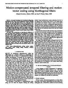
Figure 1: T h e framework for multiple description coding in the P-mode.
a single description and an MD video coder; although the MD coder may have more than one prediction loop. The second source of distortion is the mismatch between the prediction loops at the encoder and decoder. The general framework of Fig. l allows us to deal with these two sources of distortion. Roughly, F can be considered as the prediction error and Gi as a representation of the mismatch. Our general approach to video coding using MD transform coding (MDTC) uses three separate prediction paths at the encoder, to mimic the three possible scenarios a t the decoder: both descriptions received or either of the single descriptions received. Specifically, the encoder has three frame buffers, storing the previously reconstructed frames from both descriptions ( t , b ~ , k - l ) , Description One ( $ l , k - l ) , and Description Two ( 4 2 , k - l ) . Here, k represents the current frame time. For each block X , the encoder generates a predicted block Pi,i = 0 , 1 , 2 based on the reconstructed motion vector and the previous frame $;+-I. More generally, the encoder might make use of all three previous frames, t , b i , k - l , i = 0, I, 2 to produce PO. The prediction error is represented in two lay-
General framework
In general, there are two sources for distortion in an MD video coder. One source of distortion is the quantization of prediction errors. This is common between
838
ers, as shown in Fig. 1. First, the prediction error in the case when both descriptions are avajlable, F = X - PO, is coded into two descriptions Fl and FZ using an MD coder (labeled EMDC). This can be accomplished by, e.g., MDTC. We use FO to represent t_he reconstructed F from both descriptions PI and Fz, and F, to represent the reconstructed signal from only F,, for z = 1,3. In the absence of any additional information, the reconstruction from Description z alone will be P,-t PI. To reduce the future mismatch between the prediction a t the encoder and decoder, the encoder generates and codes G, = X - P,- F,. Note that in this framework, the bits used for G,, z = 1 , 2 are primarily redundancy, because a typical decoder will not use them when both descriptions are received. This portion of the total redundancy, pe,z, can be controlled directly by varying the quantization accuracy of G,. Another source of redundancy is that introduced when coding Fusing an MD coder, and is denoted pe,1. Using the MDTC coder, this redundancy is easily controlled by varying the transform parameters. In next section, we describe the details of three algorithms based on Fig. 1.
3
Multiple description transform coding of Video
In this section, we consider three different implementations of the general video coder described above. In each, we decompose the 8 x 8 central prediction error block, F , into pairs of DCT coefficients, and apply a Pairwise Correlating Transform (PCT) to each pair. In the first implementation, the strategy is to reduce the amount of mismatch between the twochannel reconstruction used for prediction and the single-channel reconstruction by using the additional prediction loops described in Section 2. The EMDC is the straightforward P C T initially described in [l], and the single-channel prediction errors GI and Gz are sent as purely redundant information by Encl and Enc2, each using a single description coder. In the second implementation, the EMDC block is the same as that of the first implementation. However, instead of using a single description quantizer for Encl and E n d , we use a generalized P C T introduced in [2] and only transmit the orthogonal complement information. In the third implementation, the strategy is to omit the additional prediction loops, but to use some additional redundancy to improve the singlechannel reconstruction. In this approach the EMDC block is the generalized P C T introduced in [a] where
four variables are used to represent the initial pair of coefficients. We do not code the single-channel prediction errors GI and Gz in this case. For redundancy allocation among the coefficients in F , it can be shown that the algorithm for assigning transform parameters for optimal redundancy allocation across pairs [l]can be extended to incorporate optimal redundancy allocation across time. This allocation of redundancy for F is common among the three different implementations below. The redundancy allocation between F and G is specific to each algorithm and is discussed below.
3.1
AIgorithm 1
In the first algorithm, we use all three prediction paths described above to limit the amount of mismatch between the two-channel frame memory and the single-channel frame memory. The “EMDC” block is the P C T applied to the two-channel prediction error, F . We use a conventional inter-mode DCT coder for the “Encl” and “Enc2” blocks in Fig. 1. Our transform-based EMDC coder takes N DCT coefficients (either from an I-frame or a P-frame), organizes them into N / 2 pairs using a fixed pairing for all frames. In the current implementation, we use the I-frame statistics to determine both N and the pairing strategy and pair the k-th largest with the (N-lc)-th largest. Each pair undergoes a pairwise correlating transform with parameter Bz (which is denoted tan81 in [Z]) and the resulting coefficients from each pair are split into two sets. The unpaired coefficients are split even/odd and appended to the P C T Coefficients. The c0efficient.s in each set are then quantized based on the desired two-channel distortion and runlength and Huffman coded. The P C T introduces a controlled amount of correlation between the resulting two coefficient streams. At the decoder, if only one description is received, the coefficients in the other description are estimated using this correlation. The transform and estimation parameters depend on the desired redundancy and on the coefficient variances estimated from selected training data. In particular, if we have a pair of sequences { A , ,B,} and apply the P C T with parameter pc to each pair of prediction errors to obtain {AC,, AD,}, then the optimal (minimum mean-squared error) single-channel reconstruction, assuming only { AC,} are received, is to form the best linear prediction of AA, and AB, using
839
algorithm allocates redundancy to F: and F:, the orthogonal coniplem_ent_sof and F2 in the Hilbert space spanned by ( F I ,F2). Specifically, this generalized transform-based EMDC coder organizes N DCT coefficients into N/2 pairs using a fixed pairing for all frames. Now, each pair undergoes a generalized P C T with parameter PI, producing four coefficients frar each pair, which are split into two sets. The coefficients belonging to FI and F2 are stored in the first 32 coefficients, while their orthogonal complements are stored in the second 3 2 coefficients. The initial 32 coefficients are then quantized based on the desired two-channel distortion, while the latter 3 2 coefficients are quantized more coarsely. The block of 64 coefficients is then runlength and Huffman encoded.
where aiA and aiB are the variances of the prediction errors. The reconstruction when only {AD,} are received follows from symmetry. In the current implementation, we do not consider optimal redundancy allocation across F and G. Rather, we use a fixed quantizer step-size on the G, coefficients that is coarser than the quantizer used on the F coefficients. In addition, we recognize from [a] that the performance of the P C T begins to degrade as the redundancy incurred by the P C T gets too large. Therefore, we use the heuristic of allocating redundancy to the P C T until it reaches the point of degraded performance, and then we begin to allocate redundancy to the single-channel prediction errors G,. One drawback of the current structure is that the p, contains only 32 coefficients each, while the G, contains 64 Coefficients. Therefore, to use a standard video coding algorithm (like MPEG or H.263) to code these data, we must send one set of overhead information (macroblock type, coded block pattern) for both F and G. This additional overhead can become costly. A more sophisticated approach, not directly considered here, would be to choose the 32 most important coefficients within G, and send that information in the same block as the 32 coefficients from p,.
3.2
4
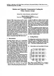
Our coder implementation is built on top of the MPEG2 MP@ML coder [6]. The coding mode decision for each macroblock follows the original MPEG2 coder. Presently, the side information and motion vectors are duplicated in both descriptions. We base our selection of the coding parameters for the MD coefficients on a preliminary analysis of the optimal redundancy allocation across both time and multiple pairs. For comparison, we also simulated two other methods that can fit into the multiple description framework. The “Interleaving Frame” method generates two subsequences containing the even and odd frames in the original sequence, separately, and then performs MPEG2 coding on the two subsequences independently. At the decoder, if only one description is available, the missing frames are simply replaced with the previous frame. This method is similar to the “multi-thread” mode presented in [7]. The “SNR Scalability” method uses the MPEG2 SNR scalability to generate a layered bitstream with the desired overall quality. The base layer is included in both descriptions and the enhancement layer is separated on a slice basis between both descriptions. We compare the single-channel distortion of the coders when they all have identical two-channel distortion. The redundancy is defined as the additional bits required by the MD coder compared to the bits required by the original MPEG2 coder generating a single bit stream with the same overall distortion. Fig. 2 shows the redundancy-rate distortion (RRD) curves [l]obtained for two CIF sequences, “flowergarden” and “ferwheel”. The GOP length is 15. The distortion is the average luminance PSNR across time, and the redundancy is expressed in terms of the percentage over the reference luminance bit rate. Note
Algorithm 2
In the second algorithm, the main prediction loop is the same as that of Algorithm 1. To transmit G1 and G2, we try to extract the more important part of the signal instead of coding the whole thing because we want t,o code G, in 32 coefficients. This is a tradeoff between the mismatch created by partial transmission of G1 and Gz and the saving in the redundancy rate. To achieve this goal, we use the generalized transform-based coder introduced in [2]. The coder generates Gfl-and Gf2, the orthogonal complements of G11 and Glz in the Hilbert space spanned by (Gl1, Gl2) and similar signals for Gz. We only transmit the Isignals for G,. Therefore, each block contains 32 coefficients for F g ,followed by 3 2 coefficients from G,. Redundancy allocation between G and F is the same as that of Algorithm 1; however, it can be shown that the redundancy allocation is optimal in this case.
3.3
Simulation Results
Algorithm 3
The third algorithm uses only the main prediction loop of Fig. 1, but the EMDC coder uses the generalized transform-based coder introduced in [2]. Thus, instead of using redundancy to code G1 and Gz, this
840
[5] V. Vaishampayan and S. John, “Interframe Balanced Multiple Description Video Compression,” in Proc. Packet Video 1999, New York, April 1999.
that with the Interleaved Frame method, the achievable redundancy cannot be controlled and only one point is obtained. As can be seen from Fig. 2, Algorithm 2 outperforms all other methods in terms of average PSNR. The hiterleaving Frame method provides the worst performance. The SNR Scalability provides good performances for low redundancies, but its relative performance deteriorates as the redundancy increases. Algorithm 1 outperforms Algorithm 3 with the exception of one point. These results indicate that some mismatch control is important; however, a complete mismatch control (as in Algorithm 1)is not necessary.
[6] “MPEG2 video test model 5,” International organization for Standardization, ISO/IEC JTCI/SC29/ W G l l no. N0400, Apr. 1993. [7] S. Wenger, “Video redundancy coding in H.263+,” in Proc. AVSPN, Aberdeen, U.K., Sept. 1997.
25
5
Conclusions
We have proposed MD video coders which use motion compensated predictions. Our MD video coders ut,ilize MD transform coding and three separate prediction paths a t the encoder, to mimic the three possible scenarios a t the decoder: both descriptions received or either of the single descriptions received. Simulation results show that it is important to have side prediction loops and transmit some redundancy information about the mismatch. If there is packet loss instead of a complete channel loss, this mismatch control will also be advantageous. Although it is more difficult to design a good MD video coder for low redundancy regions, overall, our video coder provides acceptable visual qiialities for a large range of redundancies.
1
MDTCvideo-3, SNR Scalabllty Interleaved frames
1
References [I] M. Orchard, Y. Wang, V. Vaishampayan, and A.
Reibman, “Redundancy Rate Distortion Analysis of Multiple Description Image Coding Using Pairwise Correlating Transforms,” in Proc. ICIP97, (Santa Barbara, CA), Oct, 1997.
[a]
Y. Wang, M. Orchard, and A.R.Reibman, “Optimal pairwise correlating transforms for multiple description coding,” in Proc. ICIP98, (Chicago, IL), Oct, 1998.
I
10
[3] Y. Wang, M. Orchard, and A. Reibman, “Multiple Description Image Coding for Noisy Channels by Pairing Transform Coefficients,” in Proc. IEEE 1997 First Workshop on Multimedia Signal Processing, (Princeton, NJ), June, 1997.
20 30 40 Luminance redundancy (percentage)
I
50
Figure 2 : T h e Redundancy R a t e Distortion performance of 5 coders: Our three M D T C coders, MPEG2 SNR Scalability, and the Interleaving frame coder. (a) Sequence Flowergarden; twochannel distortion 29.1 d B (b) Sequence Ferwheel; two-channel distortion 31.4 d B .
[4] V. A. Vaishampayan, “Design of multiple description scalar quantizer,” IEEE Trans. Inform. Theory, vol. 39, pp. 821-834, May 1993.
841