Accepted to the International Journal of Computer Systems Science & Engineering
Multiprocessor Checking Using Watchdog Processors I. Majzik++, W. Hohl+, A. Pataricza+,++, V. Sieh+ + Universität Erlangen-Nürnberg, IMMD III, Germany ++ Technical University of Budapest, BME MMT, Hungary
[email protected] Abstract. A new control flow checking scheme is presented, based on assigned-signature checking using a watchdog processor. This scheme is suitable for a multitasking, multiprocessor environment. The hardware overhead is comparatively low because of three reasons: first, hierarchically structured, the scheme uses only a single watchdog processor to monitor multiple processes on multiple processors. Second, as an assigned-signature scheme, it does not require monitoring the instruction bus of the processors. Third, the run-time and reference signatures are embedded into the checked program; thus, in the watchdog processor neither a reference database nor a time-consuming search and compare engine is required.
1 Introduction Massively parallel computing systems running computing intensive applications demand a high degree of fault-tolerance. Fault-tolerance techniques require error detection mechanisms with high coverage and low latency. As the majority of failures results from transient faults, concurrent fault detection is of utmost interest. However, with increasing number of processing units and parallel processes, concurrent fault detection becomes more and more difficult. Since the majority of transient processor faults results in control-flow disturbances, a widely used concurrent error detection method is concurrent control flow checking using a watchdog processor (WP). A WP as a relatively simple coprocessor compares the actual control flow represented by run-time signatures - with the previously computed reference control flow. This approach offers the possibility to connect a single WP to multiple processors, reducing the hardware overhead. Most of the WP implementations presented in the literature check single processors [10]. They can be classified according to the way how run-time signatures are generated and reference signatures are stored. Some typical methods are presented in Table 1. The methods using derived run-time signatures monitor the state of the processor bus. Assigned run-time signatures are computed and inserted into the program source by a precompiler; they are transferred to the WP by the checked processor itself. The reference is either a stored database of the admissible signature sequences or a special WP program of signature evaluation instructions [7]. (In [18] the main processor itself emulates the signature checker by utilizing unused resources). A further possibility is to transfer the reference signatures to the WP at run-time explicitly, using special instructions embedded into the program of the checked processor. There are also two approaches to integrate watchdog processors into multiprocessor systems. The Roving Monitoring Processor [19] is connected to multiple processors and monitors their states sequentially without checking their interactions. The Checker described in [9] stores the reference signatures in the local memory of the WP. The information on the control flow graph (CFG) is not stored, the admissible run-time signatures are identified by associative memory segments in the WP. Multiple processors are checked using signature queues. A further WP to be used in multiprocessors is the Extended Structural Integrity Checker (ESIC [14]). Signatures are assigned based on the high-level language structure of the program and transferred to the WP explicitly. Reference signatures are downloaded to the WP in tabular form be1
fore the beginning of program execution. The WP receives the run-time signatures and works as a finite deterministic stack automaton. In a multitasking environment, the WP always switches to the reference table of the process a signature was received from.
Stored signature database
Run-time control flow
Reference Watchdog program
Embedded signatures
Derived signatures
Asynchronous Signatured Instruction Stream [4]
Watchdog Direct Processing [13]
Assigned signatures
Extended Structural Integrity Checking [14]
Signature Structural Encoded Integrity Instruction Checking [8] Stream [17]
Basic Path Signature Analysis [21]
Table 1 Control flow checking methods The main drawback of these approaches is the (over)proportional increase of hardware and time overhead if more computing nodes and processes are added. Our paper presents a novel program control-flow checking method and a corresponding WP architecture called Signature Encoded Instruction Stream (SEIS [17]). The design goals of the SEIS project were: • Efficient checking method of multiple processors using a single WP • Checking interactions between the processes of an application • Reducing the hardware overhead by efficient utilization of the WP resources. As up-to-date microprocessors have a built-in instruction pipeline and on-chip cache memory, the assigned signature method was chosen as the focus of interest. The experimental multiprocessor system MEMSY (Modular Expandable Multiprocessor System) [1],[2],[3] was used as test-bed for the SEIS WP prototype. The paper is structured as follows. The next section presents the checking schemes applied on different levels of the target system covering both theoretical and hardware aspects. Section 3 describes the integration of the SEIS WP into MEMSY and Section 4 presents measurement results of the prototype implementation.
2 Levels of Concurrent Error Detection Our method is intended for use in multiprocessors with a UNIX-like operating system, widely used in massively parallel multiprocessors for scientific computations. An application consists of processes running the application program written in a procedural programming language. At each abstraction level: process, procedure, and statement, different checking methods and WP modules are used.The following run-time informations are monitored and therefore, included into a signature: • the statement label consisting of three sublabels identifying the location and the valid successor statements in the procedure • the procedure ID identifying the procedure of a process • the process ID identifying the application process • the ID of the processor which has sent the signature • synchronization labels (special guard signatures).
2
The lower level checks are independent from the upper level ones; each level forms a selfcontained, independent module. Each of the checks on the different levels can be executed simultaneously, assuring high operating speed. The checking modules are summarized in Table 2. An error is detected if any one of the checker modules reports an error. The checker hierarchy can detect the majority of faults at the level of their first manifestation. A fault in the program counter results in an invalid sequence of statements; it can be detected either as a wrong statement label or as a signature time-out. Stack pointer faults can result in a faulty procedure return detected by the procedure level checker. Permanent software or transient hardware faults during synchronization are detected by the process level synchronization checkers. Checker level
Checked operation
Signature information
Checker method
Statement
Statement sequence
Statement labels
Comparison
Procedure
Call and return
Procedure ID
Reference stack, comparison
Scheduling
Process and processor ID
Processor-process database check
Synchronization
Guard signatures
Reference label generation and comparison
Signature transfer rate
Signatures
Basic timer
Process
Table 2 Hierarchical checking (summary) 2.1 Statement Level Checking The execution sequence of statements in a program can be associated with a program control flow graph (CFG). Vertices represent branch-free statement sequences, edges represent the syntactically correct control flow between them. The CFG can be extracted by syntax analysis of the program source. Interrupts, data dependencies in conditional branches, and procedure calls referenced by pointers raise special problems. Conditional branches allow typically two outgoing edges from a vertex, procedure calls may call any other procedure, and interrupts, resulting in a call to an interrupt handling procedure, may occur at any time. The latter two problems belong to the procedure level and are covered in the next subsection. The statement level WP module checks the correct execution order of statements by comparison with the corresponding paths in the CFG. In order to identify the state of program execution, statement labels are assigned to the vertices of the CFG. These labels are explicitly transferred to the WP. The transfer instructions and the label values are inserted into the high level source text by a precompiler. Statement labels identify not only the CFG vertices but their (syntactically) valid successor vertices as well. Thus, checking of the statement label sequence is based only on the presently checked label and its predecessor. This eliminates the need of a WP reference database. Hence, the evaluation of the correctness of program flow is a simple combinatorial task without any time consuming database search, allowing high speed processing. The label assignment algorithm of the precompiler is as follows (for the formal description see [12]):
3
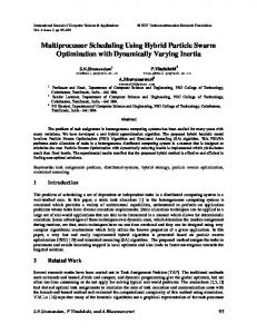
1. The CFG of the procedure is extracted. The basic control structures form subgraphs of the CFG. These subgraphs are identified according to the requirements of the encoding algorithm: that is, the number of successors of a vertex is limited in order to reduce the information to be encoded in the label identifying them. The subgraphs are composed to form the CFG of a procedure. 2. The edges of the CFG are collected into an edge trail. The problem of edge collection can be solved by well-known methods of Eulerian circuit generation. 3. A cyclic ordering of label values is defined and the edge trail is encoded. Adjacent vertices of the CFG are encoded by subsequent label values and different trails are separated by unused sublabels. After encoding the trail, all labels corresponding to the same vertex (called sublabels) are concatenated defining the statement label. In this way a statement label is a valid successor of a reference label if and only if one of its sublabels is successor of one of the sublabels of the reference label. This is the basic rule of the statement label checking. Fig. 1 presents an example C program, its CFG and the corresponding sublabel set. Using the simplest, natural ordering of the sublabels, a sublabel j is a valid successor of a reference sublabel i if and only if j=i+1. This rule is implemented by the successor function F which increases the reference sublabel value by one. The statement label sequence during the execution of the program is valid if the subsequent statement labels have successor sublabels. In the example vertex d is a valid successor of vertex b, since F(2,5,2)=(3,6,3) and (6,13,6) have 6 as common sublabel. 4. Intermittent signatures are used in the encoding of special control structures with a large number (>3) of successor or predecessor vertices. The number of such intermittent signatures (and the time overhead resulting from multiple signature transfers in a single vertex) is limited in a single signature per vertex by using a slightly modified encoding algorithm. This is based on the reuse of identical sublabels in different vertices without introducing ambiguity in the encoding [12]. a
b c a:for (j=0;j