IEEE TRANSACTIONS ON IMAGE PROCESSING, VOL. 18, NO. 2, FEBRUARY 2009
269
Multiresolution Image Representation Using Combined 2-D and 1-D Directional Filter Banks Yuichi Tanaka, Member, IEEE, Masaaki Ikehara, Senior Member, IEEE, and Truong Q. Nguyen, Fellow, IEEE
Abstract—In this paper, effective multiresolution image representations using a combination of 2-D filter bank (FB) and directional wavelet transform (WT) are presented. The proposed methods yield simple implementation and low computation costs compared to previous 1-D and 2-D FB combinations or adaptive directional WT methods. Furthermore, they are nonredundant transforms and realize quad-tree like multiresolution representations. In applications on nonlinear approximation, image coding, and denoising, the proposed filter banks show visual quality improvements and have higher PSNR than the conventional separable WT or the contourlet. Index Terms—Directional filter banks, directional wavelet transforms, image coding, multiresolution representation, nonlinear approximation, 2-D filter banks, wavelet transforms.
I. INTRODUCTION
T
HE traditional scheme to realize multiresolution image representation (MIR) is to apply 1-D filters separately in horizontal and vertical directions, commonly referred to as “separable” transform. In contrast, “nonseparable” transforms consist of 2-D filters and 2-D downsampling matrices which cannot be factorized into 1-D filter/downsampling pairs. The traditional wavelet transform (WT) is categorized as a separable transform, which is used in various applications [1], [2]. However, it has poor diagonal orientation selectivity since frequencies with different orientation are gathered into one subband in each resolution. For example, in image coding for low bit rates, reconstructed images often have blurred regions for diagonal orientations. To reduce the artifact, some combinations of 1-D separable and 2-D nonseparable filter banks (FBs) have been proposed.
Manuscript received February 22, 2008; revised September 18, 2008. First published December 16, 2008; current version published January 09, 2009. This work was supported in part by the JSPS (Japan Society for the Promotion of Science) and in part by the Global COE Program “High-Level Global Cooperation for Leading-Edge Platform on Access Spaces (C12)”. The associate editor coordinating the review of this manuscript and approving it for publication was Dr. Pier Luigi Dragotti. Y. Tanaka was with the Department of Electronics and Electrical Engineering, Keio University, Yokohama, Kanagawa, 223-8522 Japan. He is now with the Department of Information Science, Utsunomiya University, Utsunomiya, Tochigi, 321-8585 Japan (e-mail:
[email protected]). M. Ikehara is with the Department of Electronics and Electrical Engineering, Keio University, Yokohama, Kanagawa, 223-8522 Japan (e-mail:
[email protected]). T. Q. Nguyen is with the Department of Electrical and Computer Engineering, University of California, San Diego, La Jolla, CA 92093-0407 USA (e-mail:
[email protected]). Color versions of one or more of the figures in this paper are available online at http://ieeexplore.ieee.org. Digital Object Identifier 10.1109/TIP.2008.2008078
The contourlet transform [3] is one of the most well-known transforms in this category, which obtains MIR as Laplacian pyramid [4]. It is strongly related to curvelets [5]–[7] and it succeeded to represent images by using fixed (nonadaptive) implementation, which is suitable for simple representation of images. The method shows good results in nonlinear approximation (NLA); however, it is a redundant transform due to the Laplacian pyramid. Redundancy is not desirable in many practical signal processing applications, and, thus, its critically sampled improvement, CRISP-contourlet [8], was recently developed. However, it requires several sets of 2-D FBs which have specific (unusual) passband supports. A new multiscale decomposition instead of the Laplacian pyramid for the contourlet has been proposed [9]. It shows improvements on image denoising; however, it still has redundancy and does not use the traditional WT filters. This implies that we cannot apply it as a simple alternative of the WT. In [10], a simple tree-structure of 2-D FBs, called uniformquincunx directional FB (uqDFB), was presented where “quincunx” means the downsampling matrix for 2-D FBs and is defined as
. The uqDFB consists of only diamond
and fan support shape FBs. The uqDFB can also merge its two lowest frequency subbands to represent the low-frequency region effectively. It is called nonuniform quincunx directional FB (nuqDFB) and the low-frequency subband can be transformed by a separable WT. The nuqDFB shows better results in NLA than the contourlet due to its nonredundancy. However, it still remains a problem that the transformed image cannot generate the traditional quad-tree MIR, and, hence, the quad-tree coding cannot be used. To overcome this problem on the 2-D FB-based MIR, directional FB [11]–[13] is applied to the highpass subbands transformed by the separable WT in [14]. This hybrid wavelet and directional transform (HWD) is suitable for the conventional image coding method since every subband transformed by directional FBs corresponds to that of the separable WT. The HWD yields better visual quality in reconstructed images than the separable WT when the set partitioning in hierarchical trees (SPIHT) [15] is employed as an image encoder. However, many transforms by 2-D FBs are required when we need good orientation selectivity. Therefore, the computation cost for the HWD is much higher than that of the separable WT. Furthermore, a number of transforms classify and decompose images into blocks with similar directional features and process each decomposed block depending on directional information. Typical ones are directionlets [16], [17], wedgelets [18]–[20], bandelets [21], [22], and ridgelets [23]. They need the decomposition and directional features as side information, which has to be transmitted losslessly and managed carefully. Thus, one
1057-7149/$25.00 © 2008 IEEE Authorized licensed use limited to: Univ of Calif San Diego. Downloaded on December 15, 2009 at 14:43 from IEEE Xplore. Restrictions apply.
270
IEEE TRANSACTIONS ON IMAGE PROCESSING, VOL. 18, NO. 2, FEBRUARY 2009
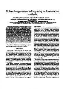
Fig. 1. Two TODFB frameworks where SepWT and DirWT referred to separable WT and directional WT, respectively. (Left) Q-TODFB (introduced in Section III). (Right) D-TODFB (introduced in Section IV).
needs nonadaptive and nonredundant transforms for some applications. Another method is not to discard high-frequency regions for image coding at low bit rates. It needs only 1-D WT filters and is based on transform along the “curves” in images [24]–[30]. In other words, 1-D filters are rotated (or skewed) to fit lines in images (such as edges between objects and background). We denote this type of WTs as “directional WT” hereafter. First, the directional WT transforms an original image with the vertical , and then transforms downsampling matrix (or vice versa). After with the horizontal one both downsamplings of the directional WT, one has four subbands corresponding to the traditional WT’s LL, LH, HL, and HH. Obviously the LL subband can be transformed recursively; thus, finally the quad-tree MIR is obtained. The directional WTs are suited for the conventional quad-tree coders. By transforming along the curves in images, the directional WTs preserve both high-frequency and low-frequency information even in low bit rates where the separable WTs often yield blurred artifacts. However, they have some drawbacks compared to the traditional separable WT. The main drawback is the computation cost to determine the curves in images. At each pixel, transforms are needed for several directions to decide the direction which maximizes the energy in LL subband (i.e., minimizes the energies in LH, HL, and HH subbands). Furthermore, some directional WTs support sub-pel and quarter-pel accuracy for each direction which would contribute to better representation of curves along with a significantly higher computation cost than that of the separable WTs. Furthermore, they need to transmit the side information of the curves to decoder. Although this barely affects the entire bit budget to be encoded, it usually requires a careful manipulation to store or transmit since it should be lossless data. To overcome the previously mentioned problems, we propose new combinations of 2-D and 1-D directional (TOD) FBs based on 2-D nonseparable FBs and the directional WT. In this paper, two TODFBs are provided to use the effective existing framework of the separable WT. Their frameworks are shown in Fig. 1. One of the TODFBs uses a combined FB before decomposing by the separable WT (left side of Fig. 1), whereas a combination is used to decompose high-frequency subbands obtained from the separable WT in the other TODFB (right side of Fig. 1). It is worth noting that these TODFBs use different 2-D FBs but have the same purpose: The first stage in the TODFB
Fig. 2. Multirate identity.
extracts the curves in the subbands by the 2-D FBs, and the second stage reduces the redundancy in these curves by the directional WTs. They do not require any adaptive processing as in the conventional directional WTs. The proposed combinations are simple, but preserve both low- and high-frequency information even after the quantization/truncation of many transformed coefficients. This paper is organized as follows. Section II gives reviews of the traditional 2-D FB-based MIRs and the directional WTs. The first TODFB shown in Fig. 1(a) is presented in Section III. In Section IV, the second approach, i.e., the structure of Fig. 1(b), is presented. Application results using TODFBs and their comparison with those of the traditional MIRs are shown in Section V. Finally, Section VI concludes the paper. II. BRIEF REVIEW A. 2-D Multirate Identity Multirate identity (often called noble identity) is a useful tool to analyze multidimensional multirate systems [1]. Its analysis side is illustrated in Fig. 2 where and are a filter and a 2 2 downsampling matrix, respectively. The synthesis one can be inferred similarly. With multirate identity, the order of a filter and a downsampling matrix can be interchanged. B. Directional Filter Banks and Contourlets The directional FB was first proposed by Bamberger and Smith [11], [12], and then their improved tree-structure version was presented in [13]. The key idea is to divide the frequency plane into several parts which correspond to the specific frequency directions. The frequency plane partition of a directional FB with eight subbands is represented in Fig. 3. With the improved structure [13], they are realized by using quincunx FBs and parallelogram ones. Their resulting downsampling matrix for the subband is
Authorized licensed use limited to: Univ of Calif San Diego. Downloaded on December 15, 2009 at 14:43 from IEEE Xplore. Restrictions apply.
(1)
TANAKA et al.: MULTIRESOLUTION IMAGE REPRESENTATION USING COMBINED 2-D AND 1-D DIRECTIONAL FILTER BANKS
271
Fig. 3. Frequency partition for the directional FB with eight subbands.
where is the decomposition level. They can divide orientations in images effectively, although all the subbands keep low-frequency energy. It often becomes a disadvantage in practical image processing such as compression, since images usually have large amounts of DC energy. In other words, to concentrate DC energy into the lowest subband is an important issue for such applications. The contourlet transform [3] can be realized by applying the directional FB to the highpass subband which is obtained from Laplacian pyramid [4]. It solves the problem of the directional FBs as mentioned previously. However, it is a redundant transform, i.e., it is regarded as a type of overcomplete transforms. Indeed, some image coding applications using the contourlet with its parent-children relationship were proposed [31], [32]. Unfortunately, they are inferior to the traditional WT image coder especially for natural images.
Fig. 4. Directional lifting steps for the directional WT. (Left) prediction step. (Right) updating step.
C. Directional Wavelet Transforms Directional WTs are based on the combination of 1-D downsampling and transforming by 1-D WT filters along the 2-D directions. Obviously lines in images, called “curves” in this paper, often flow toward diagonal orientations. A curve has similar information to its component; hence, the 1-D filtering along the curve is expected to concentrate the energy into the low-frequency subband. Some of the directional WTs [26], [28], [30] are based on the lifting implementation of the separable WTs [33]. We use this scheme for our proposed combination. The directional lifting steps are illustrated in Fig. 4. Let denote the pixel value . A prediction step for a direction with the vertical at downsampling [28] is represented as (2)
Fig. 5. Directions for the directional WT.
where
represents a lowpass branch and
(5) in which is an updating coefficient. Clearly, these lifting steps are perfect reconstruction and can be cascaded with other lifting steps similar to the separable WTs. In this paper, we use the lifting coefficients of the 9/7 WT in [33]
represents a highpass branch of the direcwhere tional lifting step and (6) (3) is a coefficient for this prediction step and in which nonnegative integer. An updating step is given by
is a
(4)
where and are scaling coefficients of lowpass and highpass branches, respectively. We define the notations of the transform directions by the directional WT as the relative pixel position from the pixel to be transformed. Some typical directions are illustrated in Fig. 5
Authorized licensed use limited to: Univ of Calif San Diego. Downloaded on December 15, 2009 at 14:43 from IEEE Xplore. Restrictions apply.
272
IEEE TRANSACTIONS ON IMAGE PROCESSING, VOL. 18, NO. 2, FEBRUARY 2009
Fig. 6. Q-TODFB decomposition.
Fig. 8. 2-D stage in the Q-TODFB framework. (Top) Frequency plane partition where numbers represent subband indices. (Bottom) Subband 2 after 1-level decomposition which represents the direction along ( 1, 1).
0
Fig. 7. Diamond FB presented as in [34].
where the direction for the separable WT is defined as (0, 1). In this paper, we consider only the directions for the vertical downsince the horizontal downsampling sampling version can be easily obtained as the transposition of the vertical downsampling one. Note that the even (odd) row to be transformed requires neighbor odd (even) rows in each lifting step for perfect reconstruction. Therefore, the directions (1, 2), ( 1, 2), etc., cannot be transformed without interpolating pixels. In the previous works [26], [28], [30], the half-pel and quarter-pel accuracies for the transform directions with pixel interpolation are permitted. Although it increases possibilities to obtain true curves, it may lead to an inefficient exploitation of correlation among pixels even if the optimal interpolation filter is designed since edges in images are generally sharp [30]. III. TODFB WITH QUINCUNX FBS This section introduces the TODFB using quincunx FBs as its 2-D stage. The image is primarily decomposed by the quincunx FBs, and then its high-frequency subbands are transformed by the directional WTs for specific directions. The entire decomposition is shown in Fig. 6. In this figure, arrowheads in “Directional WT Stage” represent the transform directions. For subbands 1, 2, and 3, the 9/7 directional lifting WT is applied in the direction (0, 1), ( 1, 1), and (1, 1) first, and then in the direction (1, 0), (1, 1), and ( 1, 1), respectively. The downsampling matrix for the low-frequency resolution (subband 0) is always
Fig. 9. Diagonally quadrant FB. (a) ideal passbands (gray areas). (b) Frequency responses presented in [35].
, which is the same as that of the separable WT. Consequently, the low-resolution image is transformed recursively by the TODFB or the separable WT. Hereafter, this kind of TODFBs is called Q-TODFB where “Q” stands on the initial letter of quincunx FB. To fit the obtained MIR for the TODFBs to the traditional quad-tree MIR, we consider one important condition. That is, where the entire downsampling matrix should be is a positive integer since the resulting subbands should keep
Authorized licensed use limited to: Univ of Calif San Diego. Downloaded on December 15, 2009 at 14:43 from IEEE Xplore. Restrictions apply.
TANAKA et al.: MULTIRESOLUTION IMAGE REPRESENTATION USING COMBINED 2-D AND 1-D DIRECTIONAL FILTER BANKS
273
Fig. 10. Finer directional WT [36]. (Left) Frequency plane partition. (Right) decomposition framework.
the aspect ratio of the original image. It will be useful in some applications. A. 2-D Stage in Q-TODFB In the Q-TODFB, the original image is first decomposed by two 2-D quincunx FBs, one consisting of a diamond filter and its complementary filter, and the other a fan filter pair. The fan FB is fundamentally realized to modulate horizontally (or ver; thus, we now consider required tically) the diamond FB by properties for a diamond FB. The most important property in the Q-TODFB or other image processing using FBs is regularity of filters since avoiding DC leakage in highpass filters is strongly desirable. In this paper, we employ the diamond FB proposed in [34] which is based on the direct optimization of its filter coefficients. Both lowpass and highpass filter sizes are 11 11 and there are two zeros at aliasing frequencies (Fig. 7). There are many methods to design 2-D diamond or fan FBs, however, the FB used here has a short highpass filter length. The regions containing high-frequency, e.g. edges and curves, usually exist locally. The short highpass filter will capture that high-frequency information well. The fan FB is determined as a modulated version of the diamond FB. Fig. 8 shows the frequency plane partition using quincunx FBs after 1-level decomposition1 and the subband 2 of Barbara by 2-D quincunx FBs. In the frequency partition, the indices refer to those in Fig. 6. For clear visualization, the magnitudes of transform coefficients are emphasized. Clearly, it captures the high-frequency coefficients which are distributed on the specific direction along ( 1, 1). Consequently, the 2-D stage in the Q-TODFB framework provides a new MIR with the downsampling matrix diag(2,2): lowpass, highpass with the horizontalvertical curves, highpass with the curves along ( 1, 1), and highpass with the curves along (1, 1). 1The
downsampling matrix of n-level decomposition is
2 0 0 2
.
B. Directional 1-D Stage in Q-TODFB The previous subsection shows that the 2-D quincunx FBs decompose directional high-frequency energy in the original image well. Then, the Q-TODFB performs the directional 1-D stage. The curve determining process required in the adaptive directional WTs no longer exists for the Q-TODFB since its 2-D stage divides the curves along the specific directions. In this stage, the subband 1 is further decomposed by the separable WT. It corresponds to transforming along the vertical and horizontal curves since the subband 1 can be classified into a subband with high-frequency components including these curves. Furthermore, the downsampling matrix for the subband 0 is diag(2, 2); thus, its size is one fourth of the original image. The Q-TODFB can be applied to the subband 0 recursively if needed. IV. TODFB WITH DIAGONALLY QUADRANT FBS In this section, another type of TODFBs is presented. It uses the separable WT as a preprocessing in each level, and then the 2-D FBs and directional WTs further decompose the highfrequency directions. For the 2-D stage, we employ a diagonally quadrant FB whose passbands are illustrated in Fig. 9(a). We describe the details of this TODFB called D-TODFB where “D” stands on the initial letter of diagonally quadrant FB. A. 2-D Stage in D-TODFB For the D-TODFB, the input image is first decomposed by the separable WT yielding four subbands LL, LH, HL and HH for each level. Traditionally, these three highpass subbands have a problem, that is, the different directional frequencies are gathered into one subband, which prevents from yielding an effective MIR. Especially two orthogonal diagonal frequencies with orientations ( 1, 1) and (1, 1) are in the HH subband. Therefore, we consider to improve its high-frequency decomposition using 2-D FBs and directional WTs as a postprocessing of the separable WT. The separable WT/diagonally quadrant FB pair was already proposed in [36] as the finer directional WT (shown
Authorized licensed use limited to: Univ of Calif San Diego. Downloaded on December 15, 2009 at 14:43 from IEEE Xplore. Restrictions apply.
274
IEEE TRANSACTIONS ON IMAGE PROCESSING, VOL. 18, NO. 2, FEBRUARY 2009
Fig. 12. Alternate directions for the HH resolution. Solid arrowheads denote the direction along Deg(1, 1) and dashed ones along Deg(1, 3).
Fig. 11. 1-level decomposition by the finer directional WT [36]. For clear visualization, the magnitudes of transform coefficients are emphasized.
in Fig. 10). However, any effective applications are not shown in it. We borrow its structure partially and add some effective features for practical image processing. The high-frequency subbands yielded by the separable WT are further decomposed by diagonally quadrant FBs. After that, six subbands compose the 1-level high-frequency resolution. In this paper, the diagonally quadrant FB is realized by using the transformation variables method proposed in [35, Example 6.2, p. 477]. Its frequency response is shown in Fig. 9(b). The MIR yielded by the finer directional WT is shown in Fig. 11. For clear visualization, the magnitudes of the transformed coefficients in high-frequency subband is emphasized. The resulting high-frequency subbands obtained by the diagonally quadrant FBs are required to have downsampling with a factor of 2. In [36], all the downsampling matrices are diag(2,1) (horizontal), however, there is an interesting property for downsampling matrices which is specific for diagonally quadrant FBs—they permit both of the downsampling matrices diag(2,1) and diag(1,2) without aliasing. Though this property is usually not important, it is very helpful for the D-TODFB to transform along the curves by the directional WTs. In the next subsection, we present the relationship between the downsampling matrices and the directional WTs.
Fig. 13. NLA comparison to determine the transform directions for D-TODFBs in the HH resolution.
B. Directional 1-D Stage in D-TODFB Similar to the Q-TODFB, the directional WT stage is required to transform the highpass subbands along the specific directions. We describe the transform directions for three high-frequency resolutions with taking into account downsampling matrices for diagonally quadrant FBs. 1) Directions for LH Subband: The frequency plane partitions for the LH region after the transform by the diagonally quadrant FBs are shown in Fig. 10. The main frequency directions are (1,2) and ( 1,2); hence, the main curve directions are (2,1) and ( 2,1), respectively. The horizontal downsampling
Fig. 14. Complete structure of the D-TODFB. (# H), (# V) are the horizontal and vertical downsamplings, respectively.
corresponding to the filtering by the diagonally quadrant FB is applied to this subband. After that, each subband in LH halves the number of columns. In other words, if we have the curve direction before the horizontal downsampling, it becomes after it. Finally, in this case, the curve directions are changed into (1,1) and ( 1,1). Consequently, the two down-
Authorized licensed use limited to: Univ of Calif San Diego. Downloaded on December 15, 2009 at 14:43 from IEEE Xplore. Restrictions apply.
TANAKA et al.: MULTIRESOLUTION IMAGE REPRESENTATION USING COMBINED 2-D AND 1-D DIRECTIONAL FILTER BANKS
275
Fig. 15. NLA results. (a) Barbara. (b) Zoneplate. (c) Lena.
sampled LH resolutions are further transformed by the directional WT along the directions (1,1) and ( 1,1), respectively, with vertical downsampling. The entire downsampling matrix for the diagonally quadrant FB and the directional WT becomes diag(2,2). 2) Directions for HL Subband: Similar to the LH subband, the curve directions after filtering by the diagonally quadrant FB are (2,1) and ( 2,1), respectively. With the vertical downsampling diag(1,2), they are changed into (1,1) and ( 1,1). Finally, these subbands are transformed by the directional WT along the directions (1,1) and ( 1,1) with horizontal downsampling. The entire downsampling matrix is also diag(2, 2). 3) Directions for HH Subband: In contrast to the other two high-frequency regions, the HH subband requires different manipulations for the directional WT. Before downsampling for the diagonally quadrant FB, the main frequency directions are (1,1) and ( 1,1), and their curve directions are ( 1,1) and (1,1), respectively. In this paper, the horizontal downsampling is considered. After that, the curve directions are changed into ( 1,2) and (1,2). The directional WT requires the vertical downsampling to yield the downsampling matrix diag(2, 2). Unfortunately, the directional WTs along ( 1,2) and (1,2) with the vertical downsampling are not permitted since the ( 1,2) and (1,2) require even (odd) rows for the even (odd) row to be transformed. Therefore, alternate methods have to be used. There are two solutions: 1) transforming along an alternative direction or 2) interpolating pixels.
Available alternative directions without interpolation are shown in Fig. 12 by using arrowheads. One is (1,1), and the other is (1,3) for the target direction (1,2). We define as the function which returns the degree of the pixel-wise , whereas direction . With this function, and . Deg(1,3) is nearer to Deg(1,2) than Deg(1,1). In contrast, the signal extension cost for Deg(1,1) at the image boundary is slightly smaller than that for Deg(1,3). The interpolating method is shown in Fig. 12 by using lines crossing dashed circles. In this figure, the dashed circles indicate the interpolated pixels. It is intuitive to transform along the direction Deg(1,2), unfortunately, the computation cost for interpolation is required for each row. The cost is depending on the interpolation filter length. For example, if we use the 6-tap FIR filter employed in the H.264/AVC motion prediction part [37], we need extra 5 additions and 5 multiplications for each interpolated pixels, and, thus, the cost will be higher than the other directions using integer pixels. V. APPLICATIONS In this section, we discuss applications using the TODFBs. For fair comparison, three benchmark results are presented. Those are the separable 9/7 WT, the contourlet and the HWD [14]. The 5-level decomposition is used for all of the transforms including the TODFBs. For the Q-TODFBs, the decomposition level for 2-D quincunx FBs can be changed, and also
Authorized licensed use limited to: Univ of Calif San Diego. Downloaded on December 15, 2009 at 14:43 from IEEE Xplore. Restrictions apply.
276
IEEE TRANSACTIONS ON IMAGE PROCESSING, VOL. 18, NO. 2, FEBRUARY 2009
Fig. 16. NLA reconstructed image comparison for 2% of kept coefficients (portions of Barbara). (Top row) From left to right: Original, 9/7WT (24.78 dB), contourlet (25.16 dB), and HWD (25.94 dB). (Bottom row) From left to right: Q-TODFB(1, 4) (25.33 dB), Q-TODFB(2, 3) (25.56 dB), D-TODFB(1, 4) (25.51 dB), and D-TODFB(2, 3) (25.66 dB).
the diagonally quadrant FB can be applied to any number of levels for the D-TODFBs. In this paper, we show results for the transforms listed as follows. • Q-TODFB with a 1-level decomposition for the quincunx FB/directional WT pair and a 4-level one for the separable WT, labeled Q-TODFB(1, 4). • Q-TODFB with a 2-level decomposition for the quincunx FB/directional WT pair and a 3-level one for the separable WT, labeled Q-TODFB(2, 3). • D-TODFB whose highest frequency resolution is decomposed by the diagonally quadrant FB/directional WT pair, labeled D-TODFB(1, 4). • D-TODFB whose two highest frequency resolutions are decomposed by the diagonally quadrant FB/directional WT pair, labeled D-TODFB(2, 3). A. Nonlinear Approximation Nonlinear Approximation (NLA) is a good measure to estimate the potential of transforms for MIR. All 5-level decomposed Barbara, Zoneplate, and Lena images are set to have the same number of the highest coefficients and the remaining coefficients are set to zeros. 1) Comparison of Transform Directions for D-TODFBs in HH: In the previous section, we showed three alternate methods to realize the transform along (1, 2) and ( 1, 2) in the HH region for the D-TODFBs. We compare these methods for several test images here and show the average of these results. Fig. 13 shows the comparison of NLA among the methods. In this figure, the alternate direction approach along (1, 1) is set as a benchmark. The other subbands have not been changed in all the methods. For the sub-pel interpolation to transform the direction along (1,2) and ( 1,2), we used the 6-tap FIR filter employed in the H.264/AVC motion prediction part [37].
Clearly, all the methods show very similar results. However, approach hereafter for the we choose the case, the filtering following reasons. In the process need slightly more signals at the boundaries than the . Furthermore, the interpolation filter will cause worse performance since the edges in images are generally sharp which is the same as describing the results in [30]. Consedirections quently, in this application, we adopt for HH due to the least computation cost. The complete analysis side of the D-TODFB is shown in Fig. 14. 2) Comparison to the Traditional Transforms: The comparison of the NLA results for various transforms is presented in Fig. 15. Clearly, the TODFBs always accomplish higher PSNR than the contourlet. They also outperform the 9/7 WT for Barbara and Zoneplate, and show comparable results to it for Lena. In the comparison with the HWD, the TODFBs have similar performance for Barbara, whereas they yield PSNR gains for Zoneplate and Lena. The reconstructed images of Barbara are shown in Fig. 16. The TODFBs preserve high-frequency regions (such as lines on the trousers) as well as the contourlets and the HWD. Furthermore, they keep smooth regions (such as skin areas) as well as the 9/7 WT. B. Image Coding Image coding is one of the key applications using MIR. Based on the NLA results, the TODFBs are expected to have good image coding performance. In this subsection, we compare the proposed TODFB with the 9/7 WT and the HWD using the SPIHT progressive image transmission algorithm [15]. Indeed, the TODFBs do not provide “true” quad-tree since high-frequency subbands have smaller sizes than a subband obtained by the separable WT. However, its aspect ratio is the same as the original image. Furthermore, the main purpose of TODFB is to
Authorized licensed use limited to: Univ of Calif San Diego. Downloaded on December 15, 2009 at 14:43 from IEEE Xplore. Restrictions apply.
TANAKA et al.: MULTIRESOLUTION IMAGE REPRESENTATION USING COMBINED 2-D AND 1-D DIRECTIONAL FILTER BANKS
277
Fig. 17. Image coding results. (a) Barbara. (b) Zoneplate. (c) Lena.
reduce energy in high-frequency subbands. It could contribute to construct an efficient coding tree in SPIHT; hence, we do not change any SPIHT algorithm. The results for various bitrates are shown in Fig. 17. The TODFBs outperform the 9/7 WT in low bit rates for rich textured images, Barbara and Zoneplate, and they shows slightly worse results at 0.4–0.5 bpp for the smoother image Lena. The TODFBs also show comparable performance to the HWD for Barbara and Zoneplate, furthermore, they uniformly outperform the HWD for Lena. Note that the distortions in reconstructed Lena are unnoticable at 0.4–0.5 bpp since all the reconstructed images keep high enough PSNR ( 35 dB) even in those bit rates. To compare the perceptual visual quality, the reconstructed images for 0.25 bpp are shown in Fig. 18 for Barbara, and Fig. 19 for Zoneplate. The diagonal lines are clearly visible in the reconstructed image using the TODFBs. Although the TODFBs(2, 3) sometimes have slightly worse PSNRs, they retain more detailed texture than the TODFBs(1, 4) (see the tablecloth area of Barbara). The HWD also shows clearer diagonal lines than the 9/7 WT; however, it distorted smooth regions obviously shown on the face and left arm of Barbara. This is because the HWD requires some levels of decompositions by directional FBs for its high-frequency subbands decomposed by the separable WT. The high-frequency information would spread into another regions caused by these convolutions by 2-D FBs in di-
rectional FBs. Finally, there will be distorted smooth regions in reconstruted images. In the papers about the adaptive directional WTs [26], [28], [30], there are more PSNR gains than that of the TODFBs compared to the 9/7 WT. However, all of these adaptive directional WTs are required to determine the optimal macro block sizes which has similar directional information. Lagrange multiplier is used to obtain the R-D optimal macro block size. It needs additional complexity to transform images. The TODFBs require smaller computation costs and memory requirements than the adaptive directional WTs since the TODFBs are a nonadaptive transform. However, the TODFBs maintain better representation for diagonal orientation in images than that of the 9/7 WT. C. Denoising The effective MIR also has potential for denoising. The denoising results are presented as the last application in this paper. The simple hard-thresholding method is used for denoising. Although there are many denoising methods including soft-thresholding, this simple method will clarify our scope of this paper which is to yield a good MIR. We set the threshold as , where is a variance of the noise and is estimated using robust median estimator [38]. Furthermore, in denoising, a new contourlet which yields sharp frequency localization has been proposed [9]. It uses multiscale decomposition instead of the Laplacian pyramid for the first-proposed contourlet. This new contourlet,
Authorized licensed use limited to: Univ of Calif San Diego. Downloaded on December 15, 2009 at 14:43 from IEEE Xplore. Restrictions apply.
278
IEEE TRANSACTIONS ON IMAGE PROCESSING, VOL. 18, NO. 2, FEBRUARY 2009
2
Fig. 18. Image coding results for 0.25 bpp (Barbara). The image on the left is the original. The remaining 2 3 images are the reconstructed ones whose transform methods are shown as follows: (Top left) 9/7WT, 26.92 dB. (Top middle) HWD, 27.37 dB. (Top right) Q-TODFB(1, 4), 27.30 dB. (Bottom left) Q-TODFB(2, 3), 27.41 dB. (Bottom middle) D-TODFB(1, 4), 27.42 dB. (Bottom right) D-TODFB(2, 3), 27.39 dB.
2
Fig. 19. Image coding results for 0.25 bpp (Zoneplate). The image on the left is the original. The remaining 2 3 images are the reconstructed ones whose transform methods are shown as follows: (Top left) 9/7WT, 10.68 dB. (Top middle) HWD, 12.62 dB. (Top right) Q-TODFB(1, 4), 13.04 dB. (Bottom left) Q-TODFB(2, 3), 12.82 dB. (Bottom middle) D-TODFB(1, 4), 12.94 dB. (Bottom right) D-TODFB(2, 3), 12.94 dB.
denoted as contourlet-MD (MD stands for multiscale decomposition), is also used for denoising. We employ the 4-level decomposition for each of the transforms. The notation of the decomposition levels for the TODFBs is similar to the previous applications. Although the contourlet-MD can have some redundancy ratios, it has been
set to 1.33 which is the same as that of the contourlet. The denoising results of Barbara and Lena for several values of are shown in Table I. Clearly, the TODFBs, especially the Q-TODFBs, have unifor Barformly better PSNRs than the 9/7 WT except bara. Furthermore, the Q-TODFB(2, 2) shows comparable re-
Authorized licensed use limited to: Univ of Calif San Diego. Downloaded on December 15, 2009 at 14:43 from IEEE Xplore. Restrictions apply.
TANAKA et al.: MULTIRESOLUTION IMAGE REPRESENTATION USING COMBINED 2-D AND 1-D DIRECTIONAL FILTER BANKS
TABLE I DENOISING RESULTS
sults to the contourlet even though the redundancy in the contourlet works well to analyze the curves in images. In contrast, the 9/7 WT shows better performance for Lena than that of the contourlet for small since the image has many smooth areas. However, the Q-TODFB(1, 3) performs comparable to or even better than the 9/7 WT in those . The contourlet-MD shows better performance than the other . The main reason is the filter choice. In transforms except this redundancy ratio, the difference between the contourlet and the contourlet-MD is only 1-D filters used. The contourlet used the 9/7 WT filters, whereas the contourlet-MD used a lowpass filter with a narrowed passband [9]. The selectivity of the filters for the redundant transforms is less restricted than that of the nonredundant ones. It would be effective for sharp frequency localization. However, the TODFBs yield good denoising results for various from the rich textured image to the smooth one among transforms using the 9/7 WT filters. VI. CONCLUSION In this paper, we propose new 2-D and 1-D diectional FB combinations named the TODFBs. They yield better results than those of the 9/7 WT, the contourlet or the HWD in the applications of NLA, image coding and denoising. Moreover, the proposed systems are very efficient. The traditional parent-children relationship for the separable WTs is straightforwardly applied to the MIRs of the TODFBs. Furthermore, the calculation of the curves in images is no longer needed in contrast to the adaptive directional WTs. In spite of the simplified structure, the proposed MIRs preserve the diagonal frequency information as well as the horizontal, vertical and low-frequency information. ACKNOWLEDGMENT The authors would like to thank Dr. Y. Lu for providing Matlab codes for his contourlet-MD [9] used in Section V-C and S. Kyochi for helping with the computer simulations.
279
REFERENCES [1] P. P. Vaidyanathan, Multirate Systems and Filter Banks. Englewood Cliffs, NJ: Prentice-Hall, 1993. [2] G. Strang and T. Q. Nguyen, Wavelets and Filter Banks. Boston, MA: Wellesley-Cambridge, 1996. [3] M. N. Do and M. Vetterli, “The contourlet transform: An efficient directional multiresolution image representation,” IEEE Trans. Image Process. vol. 14, no. 12, pp. 2091–2106, Dec. 2005 [Online]. Available: http://www.ifp.uiuc.edu/~minhdo/software/ [4] P. Burt and E. Adelson, “The Laplacian pyramid as a compact image code,” IEEE Trans. Commun., vol. COM-31, no. 4, pp. 532–540, Apr. 1983. [5] E. Candès and D. L. Donoho, “Curvelets—A surprisingly effective nonadaptive representation for objects with edges,” in Curves and Surfaces Fitting, A. Cohen, C. Rabut, and L. L. Schumaker, Eds. Nashville, TN: Vanderbilt Univ. Press, 1999. [6] J. L. Starck, E. J. Candes, and D. L. Donoho, “The curvelet transform for image denoising,” IEEE Trans. Image Process., vol. 11, no. 6, pp. 670–684, Jun. 2002. [7] E. Candès and D. L. Donoho, “New tight frames of curvelets and optimal representations of objects with piecewise C singularities,” Commun. Pure and Appl. Math., pp. 219–266, 2004. [8] Y. Lu and M. N. Do, “CRISP-contourlet: A critically sampled directional multiresolution image representation,” in Proc. SPIE Conf. Wavelet Applications in Signal and Image Processing, 2003, pp. 655–665. [9] Y. Lu and M. N. Do, “A new contourlet transform with sharp frequency localization,” in Proc. Int. Conf. Image Processing, 2006, pp. 1629–1632. [10] T. T. Nguyen and S. Oraintara, “A class of multiresolution directional filter bank,” IEEE Trans. Signal Process., vol. 55, no. 3, pp. 949–961, Mar. 2007. [11] R. H. Bamberger and M. J. T. Smith, “A filter bank for the directional decomposition of images: Theory and design,” IEEE Trans. Signal Process., vol. 40, no. 4, pp. 882–893, Apr. 1992. [12] R. H. Bamberger, “New results on two and three dimensional directional filter banks,” in Proc. 27th Asilomar Conf. Signals, Systems and Computers, 1993, pp. 1286–1290. [13] S.-I. Park, M. J. T. Smith, and R. M. Mersereau, “Improved structures of maximally decimated directional filter Banks for spatial image analysis,” IEEE Trans. Image Process., vol. 13, no. 11, pp. 1424–1431, Nov. 2004. [14] R. Eslami and H. Radha, “A new family of nonredundant transforms using hybrid wavelets and directional filter banks,” IEEE Trans. Image Process., vol. 16, no. 4, pp. 1152–1167, Apr. 2007. [15] A. Said and W. A. Pearlman, “A new, fast, and efficient image codec based on set partitioning in hierarchical trees,” IEEE Trans. Circuits Syst. Video Technol., vol. 6, no. 3, pp. 243–250, Mar. 1996. [16] V. Velisavljevic´, B. Beferull-Lozano, M. Vetterli, and P. L. Dragotti, “Directionlets: Anisotropic multi-directional representation with separable filtering,” IEEE Trans. Image Process., vol. 15, no. 7, pp. 1916–1933, Jul. 2006. [17] V. Velisavljevic´, B. Beferull-Lozano, and M. Vetterli, “Space-frequency quantization for image compression with directionlets,” IEEE Trans. Signal Process., vol. 16, no. 7, pp. 1761–1773, Jul. 2007. [18] D. L. Donoho, “Wedgelets: Nearly minimax estimation of edges,” Ann. Statist., vol. 27, no. 3, pp. 859–897, 1999. [19] M. Wakin, J. Romberg, H. Choi, and R. Baraniuk, “Rate-distortion optimized image compression using wedgelets,” in Proc. Int. Conf. Image Processing, 2002, pp. III-237–III-240. [20] A. Lisowska, “Second order wedgelets in image coding,” in Proc. EUROCON, 2007, pp. 237–244. [21] E. Le Pennec and S. Mallat, “Sparse geometric image representations with bandelets,” IEEE Trans. Image Process., vol. 14, no. 4, pp. 423–438, Apr. 2005. [22] G. Peyré and S. Mallat, “Surface compression with geometric bandelets,” in Proc. ACM SIGGRAPH, 2005, pp. 601–608. [23] E. Candès and D. L. Donoho, “Ridgelets: A key to higher-dimensional intermittency?,” Phil. Trans. Roy. Soc. Lond. A, pp. 2495–2509, 1999. [24] D. Wang, L. Zhang, and A. Vincent, “Curved wavelet transform and overlapped extension for image coding,” in Proc. Int. Conf. Image Processing, 2004, pp. 1273–1276. [25] D. Wang, L. Zhang, and A. Vincent, “Improvement of JPEG2000 using curved wavelet transform,” in Proc. ICASSP, 2005, pp. 365–368.
Authorized licensed use limited to: Univ of Calif San Diego. Downloaded on December 15, 2009 at 14:43 from IEEE Xplore. Restrictions apply.
280
IEEE TRANSACTIONS ON IMAGE PROCESSING, VOL. 18, NO. 2, FEBRUARY 2009
[26] D. Wang, L. Zhang, A. Vincent, and F. Speranza, “Curved wavelet transform for image coding,” IEEE Trans. Image Process., vol. 15, no. 8, pp. 2413–2421, Aug. 2006. [27] W. Ding, F. Wu, and S. Li, “Lifting-based wavelet transform with directionally spatial prediction,” in Proc. Picture Coding Symp., 2004, pp. 483–488. [28] W. Ding, F. Wu, X. Wu, S. Li, and H. Li, “Adaptive directional lifting-based wavelet transform for image coding,” IEEE Trans. Image Process., vol. 16, no. 2, pp. 416–427, Feb. 2007. [29] C.-L. Chang and B. Girod, “Direction-adaptive discrete wavelet transform via directional lifting and bandeletization,” in Proc. Int. Conf. Image Process., 2006, pp. 1149–1152. [30] C.-L. Chang and B. Girod, “Direction-adaptive discrete wavelet transform for image compression,” IEEE Trans. Image Process., vol. 16, no. 5, pp. 1289–1302, May 2007. [31] R. Eslami and H. Radha, “On low bit-rate coding using the contourlet transform,” in Proc. 37th Asilomar Conf. Signals, Systems and Computers, 2003, pp. 1524–1528. [32] R. Eslami and H. Radha, “Wavelet-based contourlet transform and its application to image coding,” in Proc. Int. Conf. Image Processing, 2004, pp. 3189–3192. [33] I. Daubechies and W. Sweldens, “Factoring wavelet transforms into lifting steps,” J. Fourier Anal. Appl., vol. 4, no. 3, pp. 247–269, 1998. [34] T. T. Nguyen and S. Oraintara, “Multidimensional filter banks design by direct optimization,” in Proc. ISCAS, 2005, pp. 1090–1093. [35] D. B. H. Tay and N. G. Kingsbury, “Flexible design of multidimensional perfect reconstruction FIR 2-band filters using transformations of variables,” IEEE Trans. Signal Process., vol. 2, no. 4, pp. 466–480, Apr. 1993. [36] Y. Lu and M. N. Do, “The finer directional wavelet transform,” in Proc. ICASSP, 2005, pp. IV-573–IV-576. [37] T. Wiegand, G. J. Sullivan, G. Bjntegaard, and A. Luthra, “Overview of the H. 264/AVC video coding standard,” IEEE Trans. Circuits Syst. Video Technol., vol. 13, no. 7, pp. 560–576, Jul. 2003. [38] D. L. Donoho and J. M. Johnstone, “Ideal spatial adaptation by wavelet shrinkage,” Biometrika, vol. 81, no. 3, pp. 425–455, 2003.
Masaaki Ikehara (SM’01) received the B.E., M.E., and Dr.Eng. degrees in electrical engineering from Keio University, Yokohama, Japan, in 1984, 1986, and 1989, respectively. He was Appointed Lecturer at Nagasaki University, Nagasaki, Japan, from 1989 to 1992. In 1992, he joined the Faculty of Engineering, Keio University. From 1996 to 1998, he was a visiting researcher at the University of Wisconsin, Madison, and Boston University, Boston, MA. He is currently a Full Professor with the Department of Electronics and Electrical Engineering, Keio University. His research interests are in the areas of multirate signal processing, wavelet image coding, and filter design problems.
Truong Q. Nguyen (F’05) is currently a Professor in the Electrical and Computer Engineering Deparment, University of California San Diego, La Jolla. His research interests are video processing algorithms and their efficient implementation. He is the coauthor (with Prof. G. Strang) of a popular textbook, Wavelets and Filter Banks (Wellesley-Cambridge, 1997) and the author of several Matlab-based toolboxes on image compression, electrocardiogram compression, and filter bank design. He has authored over 200 publications. Prof. Nguyen received the IEEE TRANSACTIONS ON SIGNAL PROCESSING Paper Award (Image and Multidimensional Processing area) for the paper he co-wrote with Prof. P. P. Vaidyanathan on linear-phase perfect-reconstruction filter banks (1992). He received the NSF Career Award in 1995 and is currently the Series Editor (Digital Signal Processing) for Academic Press. He served as an Associate Editor for the IEEE TRANSACTIONS ON SIGNAL PROCESSING (1994–1996), the IEEE SIGNAL PROCESSING LETTERS (2001–2003), the IEEE TRANSACTIONS ON CIRCUITS AND SYSTEMS (1996–1997, 2001–2004), and the IEEE TRANSACTIONS ON IMAGE PROCESSING (2004–2005).
Yuichi Tanaka (S’06–M’07) received the B.E., M.E., and Ph.D. degrees in electrical engineering from Keio University, Yokohama, Japan, in 2003, 2005, and 2007, respectively. He was a Postdoctoral Scholar at Keio University, Yokohama, Japan, from 2007 to 2008, supported by the Japan Society for the Promotion of Science (JSPS). From 2006 to 2008, he was also a visiting scholar at the University of California, San Diego (Video Processing Group supervised by Prof. T. Q. Nguyen). He is currently an Assistant Professor in the Department of Information Science, Utsunomiya University, Tochigi, Japan. His research interests are in the field of various and effective filter bank design and its image and video processing application.
Authorized licensed use limited to: Univ of Calif San Diego. Downloaded on December 15, 2009 at 14:43 from IEEE Xplore. Restrictions apply.