Multiresolution Techniques for the Simplification of Triangular and Tetrahedral Meshes Nikos Platis? Department of Informatics and Telecommunications University of Athens, Greece
[email protected] Abstract. We study the simplification of triangular and tetrahedral meshes using techniques based on successive edge collapses, as well as the exploitation of the generated multiple levels of detail for the effective processing of the models. Regarding triangular meshes, we present a method for the construction of progressive hulls, by suitable edge collapses; we use the generated hulls for the acceleration of intersection tests between the initial mesh and a line. Regarding tetrahedral meshes, we simplify meshes with associated vector fields; we construct progressive tetrahedral meshes by taking into account, while collapsing edges, both the geometry of the mesh and the associated field. Finally, we present an efficient algorithm for computing ray-tetrahedron intersection, which exploits Pl¨ ucker coordinates to accelerate computations; this algorithm may be used for the efficient processing of progressive tetrahedral meshes.
1
Introduction
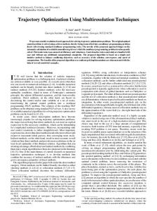
Simplification methods are used extensively as a means to face the ever increasing complexity of Computer Graphics scenes. They allow the efficient processing and display of highly complex surface and volume models, by eliminating unnecessary details given the viewing settings and other application requirements. Prominent among simplification v4 v4 edge methods are those based on iterv5 v3 v3 collapse v5 vd ative edge collapses [1]. The edge collapse operation contracts an edge fl fr vl vl vr vs vr to a single vertex (Fig. 1). Given an vo vertex ˆ , successive initial detailed mesh M split v1 v1 v2 v2 edge collapses produce a sequence of meshes with decreasing numbers Fig. 1. Edge collapse / vertex split operations of triangles, up to a coarse base mesh M 0 . The inverse of the edge collapse operation is termed a vertex split; performing vertex splits on the base mesh, in reverse order to the corresponding edge collapses, recovers the original mesh exactly. A progressive mesh is a ˆ consisting of the base mesh M0 and the sequence of vertex representation of M splits that produce the original mesh. The progressive mesh construction can be adapted for many purposes. The two issues that affect the resulting progressive ?
Supervisor: Assoc. Prof. Theoharis Theoharis
mesh are the order in which the edges are collapsed and, for each collapse, the position of the new vertex [1–6]. Progressive meshes can also be extended to support selective refinement [7–9], so that detail can be added only on specific parts of the mesh, as required by the application.
2
Progressive Hulls for Intersection Applications
In this section we focus on triangular meshes. We extend and refine an algorithm for the construction of progressive hulls, which are hierarchical nested hulls of triangle meshes, constructed by suitable adaptation of progressive meshes. We use a new, efficient formula for assigning priorities to edge collapses, and we propose several conditions in order to produce higher quality hulls that enclose the original mesh tightly. Furthermore, we present an algorithm that exploits progressive hulls and a selective refinement framework in order to considerably accelerate intersection queries on a given mesh [10]. 2.1
Background and Related Work
Hierarchical bounding volumes (or hulls) are essential tools for accelerating intersection queries on 3D surface models, and are thus used in various applications such as ray tracing and collision detection. Hierarchical bounding volumes enclose the original model in nested sets of “boxes” of various shapes, which successively restrict the areas of potential intersections. The choice of shape is a compromise between void space and simplicity of the bounding volume with the aim of maximizing the speed of intersection tests [11, 12]. Progressive hulls [13] are an application of progressive meshes for the generation of hulls of closed manifold meshes. The reasoning for their construction is straightforward: the edge collapse operation affects the mesh only locally, on the triangles at the neighborhood of the collapsed edge; thus if, for each edge collapse, the generated vertex is placed on the “outside” of all these triangles, then the resulting mesh will completely enclose the original mesh, forming an outer hull for it. 2.2
Progressive Hull Construction
The position of the vertex resulting from each edge collapse is computed by solving a linear programming problem: the constraints ensure that the vertex is on the outside of all the faces around the collapsed edge, and the objective function minimizes the volume (void space) between the faces around the edge and those around the new vertex (which is the only affected part of the model). The original progressive hull construction algorithm assigns this volume as the priority of each edge collapse. This 1st stategy for assigning priorities is obviously rational, however it is not very efficient since only a small fraction of the computed collapses are actually applied to the mesh while most are recomputed in the course of the algorithm.
For this reason, we propose a 2nd stategy for assigning edge collapse priorities. Specifically, we compute the “center” of the vertices around the collapsed edge and assign as collapse priority the volume between this center and the faces around the collapsed edge; this heuristic is based on the assumption that collapsing edges on areas where the faces of the mesh are small or relatively planar entails little simplification error. Using this strategy, the costly optimization problem is solved only when each collapse is applied to the mesh. In order to produce higher quality hulls, we propose several enhancements to the original algorithm. We ensure that candidate edge collapses do not modify the topology of the mesh [14]; we restrict the valence of each vertex up to a maximum number of faces; we ensure that the compactness of the faces of the mesh does not degrade significantly; and we reject collapses that change the orientation of the faces abruptly. Results We generated progressive hulls for various models using the two strategies described above for assigning edge collapse priorities. In terms of quality, the 1st strategy produced better results, but the 2nd strategy was always close (Fig. 2). In terms of speed, however, the 2nd strategy outperformed the 1st one almost six times for all models tested.
Fig. 2. Horse: Initial model (96,966 faces), hulls of 2,000 and 200 faces generated with the 2nd strategy.
2.3
Testing for Intersections Using Progressive Hulls
The progressive hulls constructed are used for the efficient testing of intersections between a triangle mesh and a ray. Our algorithm starts by checking for an intersection between the base hull, which has the least number of faces, and the ray. If an intersection exists, the algorithm selectively refines the progressive hull in the vicinity of the intersection(s) detected, via suitable vertex splits, and checks further the triangles affected by the refinement. Owing to the localized effect of vertex splits, the algorithm continuously restricts the areas of the mesh where intersections may
occur, up to individual faces on the original mesh (Fig. 3). This iteration is repeated until the original mesh is reached or no more intersections are found.
Fig. 3. A progressive hull of the balljoint model intersected by a line segment. The 2,000 face base hull has been locally refined around the intersection point.
We note that several schemes exist for the selective refinement of progressive meshes [7, 8]. The one that we use has the property to restore the intermediate levels of the progressive hull exactly; selective refinement schemes that do not possess this property are not suitable for our algorithm, since the intermediate levels that they produce may not retain the enclosing property of the progressive hull hierarchy.
Results The efficiency of our algorithm using progressive hulls for accelerating the intersection test between a ray and a triangle mesh, depends on three factors: how well the hull encloses the original model, the total number of ray-triangle intersection tests performed, and the number of vertex splits required. All three factors are a function of the base hull utilized: a base hull with few triangles leads to few ray-triangle tests but requires many vertex splits and encloses the mesh loosely, and vice versa. In our implementation, moderately sized base hulls (500–3000 faces) were proven the most efficient for all the models tested (Fig. 4).
60
Rocker Arm Screwdriver Dinosaur Horse Igea Balljoint
55
Times for intersection tests (ms)
In any case, our algorithm offers significant performance gains for ray-triangle mesh intersection tests. Progressive hulls generated with the two strategies described in the previous section demonstrated comparable performance, only a little worse for the 2nd strategy, but given the significantly less time required for their generation, they appear to be well suited for this task.
50 45 40 35 30 25 20 15 10 200 1000
2000
3000
4000
5000
10000
Number of faces of hull
Fig. 4. Times for intersection tests with pro-
Compared to k-DOPs, one of gressive hulls of various numbers of faces. the most efficient bounding volume hierarchies, our ray-triangle intersection test using progressive hulls proved faster for all test models used; it should be noted, though, that k-DOPs are optimized for intersection tests between triangle meshes.
3
Simplification of Vector Fields over Tetrahedral Meshes
In this section we shift our focus to the simplification of tetrahedral meshes. Such meshes are used for the representation of volume models, usually with scalar or vector fields associated with their vertices. We present a simplification method based on iterative edge collapses for tetrahedral meshes with associated vector fields, and provide several variations of the algorithm. We develop a general method that adapts edge collapse based surface simplification methods to vector fields over tetrahedral meshes, and use it to optimize the position and field value of the vertex resulting from an edge collapse. We enforce several conditions in order to maintain the mesh and field topology, as well as the mesh boundary [15, 16]. 3.1
Background and Related Work
Other authors have treated, thus far, either tetrahedral meshes with associated scalar fields or scattered data vector fields – isolated points with associated vector values but without connectivity information. Concerning scalar fields over tetrahedral meshes, most methods use simplification techniques based on iterative edge collapses [17–21]; the edge collapse operation may be extended in a natural way so that it can be applied to tetrahedral meshes, thus producing progressive tetrahedral meshes, which retain all the desirable properties of (surface) progressive meshes. Simplification of scattered data vector fields has mostly used vertex clustering techniques [22–25], aiming to preserve the topology of the field. 3.2
Vertex Placement Strategies
The first important element of a simplification method that uses edge collapses is the strategy by which the resulting vertex is defined. Half-Edge Collapses The first vertex placement strategy that we applied allows edges to contract only to either of their endpoints and retains the original field value at the target point. This simplification scheme is highly efficient, since no computations are made in order to determine the new vertex. Moreover, since the original vertices and field values are used throughout, the possibility to distort the field topology is reduced. Optimal Placement In spite of the advantages mentioned above, half-edge collapses are restricted and may not offer the optimal simplification result. For this, an optimization method is required in order to compute the position of the vertex resulting from an edge collapse and the corresponding field value. We propose a general technique that extends surface simplification methods that optimize the resulting vertex, to vector fields over tetrahedral meshes. In
(a)
(b)
(c)
Fig. 5. A vector field defined on a 2D mesh is embedded in 3D. The two generated surfaces are simplified concurrently in order to define the resulting vertex position and field value.
order to apply such methods to tetrahedral meshes, we must work in 4D space; thus we map the mesh and associated field to 4D, by constructing two 4D hypersurfaces using the relations: p = (px , py , pz , pw ) = (vx , vy , vz , 0) + (0, fx , fy , fz ) m = (mx , my , mz , mw ) = (vx , vy , vz , 0) + u0 (0, fx , fy , fz )
(1)
(where (vx , vy , vz ) is the position and (fx , fy , fz ) the field value at a vertex, and for convenience we use u0 = 12 ). We note that only one hypersurface is not sufficient to capture the directionality of the field. The two 4D hypersurfaces are simplified concurrently using any (3D) surface simplification algorithm that uses the equations of the planes around the collapsed edge, extended to 4D by the simple addition of one dimension (we have applied the Quadric Error Metric algorithm [2]). The two resulting points on the hypersurfaces can provide, by inverse mapping to 3D, the required vertex position and field value (Fig. 5). 3.3
Error Estimation
The second element of the simplification algorithm is the formula by which the error induced to the field by each edge collapse is approximated. Compound Error As a general metric of the simplification error, we propose a compound error metric as a weighted sum of several components: E = wFA EFA + wFL EFL + wD ED + wC EC + wV EV In brief, the first two components are estimates of the error induced on the vector field, measuring respectively the deviation angle (EFA ) and the vector difference (EFL ) of the field before and after the collapse; the third (ED ) is an estimate of the error on the mesh itself (only applicable when collapsing edges near the boundary), measuring the maximum dihedral angle of corresponding boundary faces; the last two components control the quality of the generated mesh in terms of tetrahedra compactness (EC ) and vertex valence (EV ).
Fig. 6. The pipe model, original and simplified at 50%, 25% and 10% using SC1 (half-edge collapses).
Quadric Error When applying our algorithm for optimal placement, it is possible to use a more direct approach for error estimation. The surface simplification algorithm employed optimizes the vertex resulting from an edge collapse with respect to some estimation of the simplification error. Given our mapping of the field to 4D, this estimation provides a measure of the impact of the collapse to the original field. In the case of the quadric error metric that we employ, the error estimation is the sum of squared distances of the resulting vertex to the set of faces around the collapsed edge. Our simplification algorithm computes two such distances, one for each of the surfaces constructed out of the p and m points. We arbitrarily choose to use the distance on the outer (p) surface for error estimation; alternatively, one could take the distance on the inner (m) surface or a combination of the two. 3.4
Results
We simplified several datasets (Fig. 6) using three simplification configurations: SC1 Half-edge collapses with the compound error metric. SC2 Optimal placement with the compound error metric. SC3 Optimal placement with the quadric error metric. SC1 was the fastest configuration, as expected, but in terms of quality its results varied considerably depending on the error weights chosen; in any case, the field error components proved most important. SC2 performed unsatisfactorily, both in terms of speed (it was by far the slowest configuration), which was expected since it computes both the quadric and the compound error, and in terms of quality, which may be due to the error weights tested. Finally, SC3 that uses our quadric error metric for optimized edge collapses, was always slower than SC1 but produced at least as good results as the best error weight combinations for SC1 without requiring any user intervention.
4
Fast Ray-Tetrahedron Intersection
Ray-tetrahedron intersection tests are at the heart of many algorithms for the processing and rendering of tetrahedral meshes. However, this problem is not treated directly in the current litterature. Motivated by our work with tetrahedral meshes in the previous section, in the current section we present a specialized algorithm for this test [26].
4.1
Background and Related Work
Ray-tetrahedron intersection tests can be perfomed either using a generic rayconvex polyhedron intersection test [27], or by combining the results of raytriangle intersection tests [28] for the four faces of the tetrahedron; our algorithm follows the second approach. 4.2
Ray-Tetrahedron Intersection Algorithm
Ray-Triangle Intersection using Pl¨ ucker Coordinates Pl¨ ucker coordinates [29, 30] are a way of specifying directed lines in three-dimensional space using six-dimensional vectors. Given a ray r determined by point p and direction `, its Pl¨ ucker coordinates are given by the six-vector πr = {` : ` × p} = {ur : wr }
(2)
Given two directed lines r and s, the permuted inner product πr ¯ πs = ur · ws + us · wr
(3)
indicates their relative orientation: πr ¯ πs > 0 ⇔ s goes counterclockwise around r πr ¯ πs < 0 ⇔ s goes clockwise around r πr ¯ πs = 0 ⇔ s intersects or is parallel to r This property is the basis of a ray-triangle intersection test. Suppose we are given a ray r and a (b) (c) triangle ∆ with edges e0 , e1 , e2 . (a) Then r intersects ∆ iff it has the same orientation (cw or ccw) rela- Fig. 7. (a) The ray enters the triangle; (b) The ray leaves the triangle; (c) The ray and the tive to all its edges or it intersects triangle do not intersect. at most two of its edges (Fig. 7). This test is robust and efficient since it requires few floating point operations, no division, and relies only on sign comparisons; moreover, calculations for an edge can be shared among neighboring triangles. Ray-Tetrahedron Intersection Algorithm and Optimizations Our raytetrahedron intersection algorithm tests each face of the tetrahedron in turn and determines if the ray intersects and enters or leaves the tetrahedron through it, according to the above test; if either of the entering or leaving face has been found, the relevant sign tests need not be performed for the remaining faces. This basic algorithm can be optimized in several ways. On a first level, as already mentioned, calculations for each edge can be shared among the two neighboring faces. Moreover, computations pertaining to some of the faces of the tetrahedron may be omitted once the first of the intersected faces is determined.
On a second level, in several cases it is sufficient to compute and examine, for each face considered, only some of the permuted inner products of the ray and the face edges; this optimization level increases the code complexity of the algorithm considerably, but leads to significant performance gains. 4.3
Results
Time per intersection test (µs)
Test results for our algorithm 2.0 are summarized in Fig. 8. Pl¨ ucker1 1.8 and Pl¨ ucker2 correspond to the two 1.6 optimization levels of our basic al1.4 gorithm, as described briefly above; Pl¨ ucker3 corresponds to another form 1.2 1.0 of optimization that we considered, but which did not offer any further 0.8 Plücker 1 Plücker 2 improvements; Haines corresponds 0.6 Plücker 3 Haines to the ray-convex polyhedron algoMöller−Trumbore 0.4 0 10 20 30 40 50 60 70 80 90 100 rithm of [27]; and M¨ oller-Trumbore Percentage of intersected tetrahedra corresponds to our optimized algoFig. 8. Results for ray-tetrahedron intersecrithm but with the ray-triangle intion tests. tersection tests substituted by the test of [28] which is considered one of the most efficient general-purpose raytriangle intersection tests. It is obvious that our fully optimized ray-tetrahedron intersection algorithm is the fastest in all cases. The gains relative to a generic ray-convex polyhedron intersection algorithm are obvious, as is the suitability of our ray-triangle intersection test based on Pl¨ ucker coordinates for this specific problem.
References 1. Hoppe, H.: Progressive Meshes. In: SIGGRAPH 96 Conference Proceedings. (1996) 99–108 2. Garland, M., Heckbert, P.S.: Surface Simplification Using Quadric Error Metrics. In: SIGGRAPH 97 Conference Proceedings. (1997) 209–216 3. Gu´eziec, A.: Locally Toleranced Surface Simplification. IEEE Transactions on Visualization and Computer Graphics 5(2) (1999) 168–189 4. Lindstrom, P., Turk, G.: Fast and Memory Efficient Polygonal Simplification. In: Proceedings of IEEE Visualization ’98. (1998) 279–286 5. Garland, M.: Multiresolution Modeling: Survey & Future Opportunities. State of the Art Report, Eurographics ’99 (1999) 6. Puppo, E., Scopigno, R.: Simplification, LOD and Multiresolution — Principles and Applications. Eurographics ’97 Tutorial Notes (1997) 7. Hoppe, H.: View-Dependent Refinement of Progressive Meshes. In: SIGGRAPH 97 Conference Proceedings. (1997) 189–198 8. Xia, J.C., Varshney, A.: Dynamic View-Dependent Simplification for Polygonal Models. In: Proceedings of IEEE Visualization ’96, IEEE (1996) 327–334
9. De Floriani, L., Magillo, P., Puppo, E.: Building and Traversing a Surface at Variable Resolution. In: Proceedings of IEEE Visualization ’97. (1997) 103–110 10. Platis, N., Theoharis, T.: Progressive Hulls for Intersection Applications. Computer Graphics Forum 22(2) (2003) 107–116 11. Klosowski, J.T., Held, M., Mitchell, J.S., Sowizral, H., Zikan, K.: Efficient Collision Detection Using Bounding Volume Hierarchies of k-DOPs. IEEE Transactions on Visualization and Computer Graphics 4(1) (1998) 21–36 12. Gottschalk, S., Lin, M.C., Manocha, D.: OBBTree: A Hierarchical Structure for Rapid Interference Detection. In: SIGGRAPH 96 Conference Proceedings. (1996) 171–180 13. Sander, P.V., Gu, X., Gortler, S.J., Hoppe, H., Snyder, J.: Silhouette Clipping. In: SIGGRAPH 2000 Conference Proceedings. (2000) 327–334 14. Dey, T.K., Edelsbrunner, H., Guha, S., Nekhayev, D.V.: Topology Preserving Edge Contraction. Publications de l’Institut Math´ematique (Beograd) 66(80) (1999) 23– 45 15. Platis, N., Theoharis, T.: Simplification of Vector Fields over Tetrahedral Meshes. In: Proceedings of Computer Graphics International 2004, Crete (2004) 174–181 16. Platis, N., Theoharis, T.: Techniques for Simplification of Vector Fields over Tetrahedral Meshes with Error Evaluation (2004) (Under review). 17. Staadt, O.G., Gross, M.H.: Progressive Tetrahedralizations. In: Proceedings of IEEE Visualization ’98. (1998) 397–402 18. Chiang, Y.J., Lu, X.: Progressive Simplification of Tetrahedral Meshes Preserving All Isosurface Topologies. Computer Graphics Forum 22(3) (2003) 493–504 19. Trotts, I.J., Hamann, B., Joy, K.I.: Simplification of Tetrahedral Meshes with Error Bounds. IEEE Transactions on Visualization and Computer Graphics 5(3) (1999) 224–237 20. Cignoni, P., Constanza, D., Montani, C., Rocchini, C., Scopigno, R.: Simplification of Tetrahedral Meshes with Accurate Error Evaluation. In: Proceedings of IEEE Visualization 2000. (2000) 85–92 21. Trotts, I.J., Hamann, B., Kenwright, D., Joy, K.I.: Simplification of Tetrahedral Meshes Using a Quadratic Error Metric. In: NSF/DoE Lake Tahoe Workshop on Hierarhical Approximation and Geometrical Methods for Scientific Visualization. (2000) 22. Heckel, B., Weber, G., Hamann, B., Joy, K.I.: Construction of Vector Field Hierarchies. In: Proceedings of IEEE Visualization ’99. (1999) 19–25 23. Telea, A., van Wijk, J.J.: Simplified Representation of Vector Fields. In: Proceedings of IEEE Visualization ’99. (1999) 35–42 24. Tricoche, X., Scheuermann, G., Hagen, H.: A Topology Simplification Method For 2D Vector Fields. In: Procedings of IEEE Visualization 2000. (2000) 359–366 25. Garcke, H., Preußer, T., Rumpf, M., Telea, A., Weikard, U., van Wijk, J.J.: A Phase Field Model for Continuous Clustering on Vector Fields. IEEE Transactions on Visualization and Computer Graphics 7(3) (2001) 230–241 26. Platis, N., Theoharis, T.: Fast Ray-Tetrahedron Intersection Using Pl¨ ucker Coordinates. journal of graphics tools 8(4) (2003) 37–48 27. Haines, E.: Fast Ray–Convex Polyhedron Intersection. In Arvo, J., ed.: Graphics Gems II. Academic Press (1991) 247–250 oller, T., Trumbore, B.: Fast, Minimum Storage Ray/Triangle Intersection. jour28. M¨ nal of graphics tools 2(1) (1997) 21–28 29. Erickson, J.: Pl¨ ucker Coordinates. Ray Tracing News 10(3) (1997) 30. Shoemake, K.: Pl¨ ucker Coordinate Tutorial. Ray Tracing News 11(1) (1998)