Cybernetics and Systems: An International Journal, 33 : 69± 99, 2002 Copyright # 2002 Taylor & Francis 0196 - 9722/ 02 $12.00 + .00
MULTIVARIABLE FUZZY GENERALIZED PREDICTIVE CONTROL
ZHANG HUAGUANG Department of Automatic Control, Northeastern University, Shenyang, P. R. China LILONG CAI Department of Mechanical Engineering, Hong Kong University of Science and Technology, ClearWater Bay, Kowloon, Hong Kong
A Takagi-Sugeno (T-S) fuzzy model is used to express non-linear dynamic systems with time-delay in this paper, and an on-line identi® cation algorithm is presented regarding its parameters and structures. A multivariable fuzzy generalized predictive control approach is proposed based on the identi® ed fuzzy model by means of the generalized predictive control principle. The closed-loop stability is analyzed in detail. A simulation study for the multivariable load system of a boiler-turbine unit shows that the approach is superior to convention load control systems.
INTRODUC TION There are many complex industrial processes, such as the load control system of a power plant, that have non-linear dynamics with time-varying parameters and with large time delays. It is usually very dif® cult to design a satisfactory control system for such processes (Hecker, 1997). This work was supported by the Foundation for University Key Teachers and the Foundation for Doctoral Special Branch by the Ministry of Education of P. R. China. The authors would like to thank the reviewers for their constructive comments. Addresscorrespondence to Dr. ZhangHuagang, Department of Automatic Control, Northeastern University, Shenyang, 110006, P.R. China. Fax: 852-23581543 , E-mail:
[email protected] 69
70
Z. HUAGUANG AND L. CAI
The adaptive control of non-linear systems is one of the most often presented methods. The central concept of this approach is to transform non-linear system dynamics into an appropriate linear model around an equivalent point (at the origin, usually), so that conventional linear control techniques can be applied (for details, see Tong, Tang, and Wang 2000). A key assumption in these studies is that the system nonlinearities are known a priori and they are linerizable. This creates a limitation in the theory because the real system may always contain uncertain disturbance and unmodeled dynamics. The design of a highly accurate modelling method for non-linear systems and a non-linear model-based adaptive control methods help to deal with these limitations. A fuzzy model is a non-linear model and is suitable for expressing non-linear dynamic properties with uncertainty. T-S fuzzy models have been proved to be universal approximators for any non-linear system (Zhang, Cai, and Bien, 2000; Buckley, 1993; Wang, 1995). In this paper, a fast, on-line identi® cation method of a T-S fuzzy model is developed that can be used to model the time-varying, non-linear dynamic processes with high accuracy. In addition, the identi® ed T-S fuzzy model can be equivalently transformed into a linear model with time-varying parameters at each sample-instant. A novel multivariable generalized predictive control (GPC) based on a T-S fuzzy model is developed in this paper. This is because GPC is a long-range predictive controller (Clark, Mohtadi, and Toffs, 1987). Its feature lies in the long-range prediction of the future outputs of processes, i.e., when we assert the near future control u(t ± 1) at each sample-instant t, all the future output responses along some horizon that is signi® cantly affected by the current control are also determined. By longrange prediction, GPC can be used to control complex processes with either varying dead-time or whose model is overparameterized (Clark, Mohtadi, and Toffs, 1987). On the other hand, the main problem in using traditional GPC is how to obtain the exact mathematical model of the controlled process. Obtaining an exact mathematical model is usually very dif® cult in practice. But the fuzzy model of a process is easy to obtain by means of experts’ experience, judgment, and (or) input=output data of the process. Therefore, the fuzzy model-based generalized predictive control (FMC) may be a powerful and advanced control approach in the future. Stability analysis of the fuzzy control systems is very dif® cult. A puzzling problem is how to construct a suitable Lyapunov function V (x)
FUZZY GENERALIZED PREDICTIVE CONTROL
71
when using the Lyapunov direct method (Dai, 1993; Spooner, 1997). Tanaka and Sugeno suggest a stability checking condition (Tanaka and Sugeno, 1992) that a designer can use to design a fuzzy control law. Unfortunately, the stability condition enquires that for all the local linear models a common positive-de® nite matrix P must be found to satisfy the Lyapunov equation. However, in many cases, this is a dif® cult problem to solve, if not an impossible one. One way of getting round the problem of determining the common P is suggested in Cao (Cao, 1997). This method conveys the stability analysis of a fuzzy control system to the stability analysis of linear time-varying ``extreme’’ subsystems. Unfortunately, these results may tend to give a more conservative controller design. In addition, all the above methods only give suf® cient conditions for stability of the fuzzy control systems, and for many systems the stability conditions are very dif® cult to satisfy. Sezer presented a method to check the stability by the interval matrices, but the research result was limited to Morishima-type interval matrices (Sezer and Siljak, 1994). This paper presents a new and effective method to use the interval matrices that can also be used in other complex discrete systems directly. FUZZY MODELLING METHOD Algorithm of Fuzzy Identification A typical discrete-time fuzzy model for a multi-input single-output (MISO) system with p inputs may be expressed by n fuzzy rules (Takagi and Sugeno, 1985) of the following form Ri : if
y(t) is Mi1 ; y(t ± 1) is Mi2 ; . . . y(t ± ny ) is Miny ‡1 ;
u1 (t ± d1 ) is Miny ‡2 ; . . .
u1 (t ± n1 ± d1 ) is Miny ‡n1 ‡2;...; up (t ± np ± dp ) is Miny ‡n1 ‡¢¢¢‡np ‡p‡1 then yi = Pi0 ‡ Pi1 y(t) ‡ Pi2 y(t ± 1) ‡ ¢ ¢ ¢ ‡ Piny ‡1 y(t ± ny )
‡ Pin ‡2 u1 (t ± d1 ) ‡ ¢ ¢ ¢ ‡ Pny ‡n1 ‡¢¢¢‡np ‡p‡1 up (t ± np ± dp ) ‡ x(t); y i = 1; 2; . . . ; n:
(1)
In (1), Ri means the ith rule, Mij is a fuzzy subset, yi is the output from the ith rule, Pij is a parameter of the consequence part and Pi0 is a
72
Z. HUAGUANG AND L. CAI
constant term in the consequence part, u1 (:); . . . ; up (:) are input variables, y(:) is an output variable, di is the dead-time of the ith input variable, and x(t) is uncorrelated noise disturbance. For convenience, let: x1 (t) = y(t) x2 (t) = y(t ± 1) .. . xny ‡1 (t) = y(t ± ny )
xny ‡2 (t) = u1 (t ± d1 )
xny ‡3 (t) = u1 (t ± 1 ± d1 ) .. . xm (t) = up (t ± np ± dp )
(2)
Pp where m = ny ‡ 1 ‡ i= 1 (ni ‡ 1). Then we get Equation (3) from Equation (1): Ri : if x1 is Mi1 ; x2 is Mi2 . . . xm is Mim ; then yi = Pi0 ‡ Pi1 x1 ‡ Pi2 x2 ‡ ¢ ¢ ¢ ‡ Pim xm ‡ x(t)
(3)
where xj is a generalized input variable. The membership function of a fuzzy variable, expressed by premise parameters, will be of a convex type and formed by straight lines. Here the noise x(t) is supposed to be white noise with a zero mean and variance s2x . Given an input vector (x10 ; x20 ; . . . ; xm0 ), the output y^ can be inferred by taking the weighted average of the yi ; i = 1; 2; . . . ; n: , n n X X i i y^ = Gy Gi (4) i= 1
i= 1
where n is the number of fuzzy rules, yi is obtained from the input vector by the equation of the ith rule, and the weight Gi signi® es the truth value of the premise of the ith rule for the input calculated by Gi =
m ^
j= 1
Mij (xj0 )
where the symbol
(5) V
denotes a fuzzy minimum operator.
FUZZY GENERALIZED PREDICTIVE CONTROL
73
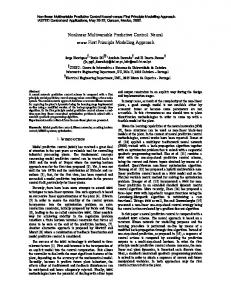
Many papers have appeared recently about the identi® cation methods about the T-S fuzzy model. In the original paper by Takagi and Sugeno (Takagi and Sugeno, 1985), an effective premise structure identi® cation method is presented based on a fuzzy partition of the input variable space into some subspaces using IF-T HEN rules. The complex method is used for the premise parameter identi® cation, which is very effective, but consumes too much computing time. Pokorny and Osmera present a parameter identi® cation method using genetic algorithms (GA) that has satisfactory precision, but is too sensitive to the parameter uncertainty (Pokorny and Osmera, 1997). A high-order neural network (HONN) is proposed (Park, 1998), and its approximation capability to non-linear dynamical systems is powerful, but the initial states must be selected carefully. For practical control engineering, an identi® cation approach that is highly accurate and uses less computing time is very important. The latter is especially necessary for on-line modelling and control of a fast industrial process. In this paper, we develop an effective identi® cation approach to the fuzzy model in order to apply it to a load control system of a 200 MW boiler-turbine unit in a power plant. The outline of the algorithm is shown in Figure 1.
Figure 1. The outline of the algorithm.
74
Z. HUAGUANG AND L. CAI
Premise Structure Identification. There are two problems concerned with premise structure identi® cation. One is how to ® nd which variables are necessary in the premise of a rule. The other is how to form the optimal fuzzy partition of the input space. Each fuzzy rule expresses a local input=output relation that holds in the fuzzy subspace de® ned by its premise. The performance index PER is de® ned as the mean square error between the model output and the measured real output, i.e.,
PER =
"
mi 1X ( y^ (k) ± y(k)) 2 n k= 1
#1=2
(6)
where y(k) is real plant output, y^ (k) is the fuzzy model output, and m i , is total identi® ed time. The premise structure identi® cation algorithm is given as follows: (1) An ordinary linear model is identi® ed by means of the linear stepwise regression method. Its PER is solved and written as PER (1). (2) A fuzzy model consisting of two fuzzy rules is constructed by ® rst dividing the range of x 1 into small and large fuzzy subspaces R1 : if x1 is small then . . . R2 : if x1 is large then . . . Then, the premise parameters, the consequence structure, and the parameters are identi® ed, and the PER of the model is obtained. Similarly, a fuzzy model dividing the range of xi ; i = 1; 2; . . . ; m; is identi® ed and its PER is calculated. Among the m models, the one with the least PER is found. Its PER and premise structure are denoted as PER (2) and ST R (2), respectively. (3) Suppose the premise variable of ST R (2) is xi , as shown in Figure 2(a) . At this step, each premise structure consists of three fuzzy subspaces. There are two ways to construct a premise structure. One is that the range of xi itself is divided into three fuzzy subspaces as shown in Figure 2(b). The other is that another variable (xj , say), is put in ST R (2) and its range is divided into two fuzzy subspaces as shown in Figure 2(c), (d). The premise structure of Figure 2(b) is
FUZZY GENERALIZED PREDICTIVE CONTROL
75
Figure 2. A group of premise structures.
R1 : if xi is small then . . . R2 : if xi is medium then . . . R3 : if xi is large then . . . and the premise structure of Figure 2(d) is R1 : if xi is large 1 xj is small2 then . . . R2 : if xi is large 1 xj is large2 then . . . R3 : if xi is small1 then . . . For each premise structure that can be constructed at this step, a fuzzy model is identi® ed and its PER is calculated. A fuzzy model with the least PER is found among those. Its PER and premise structure are written as PER (3) and ST R (3), respectively. (4) Suppose we have searched out a premise structure ST R (i ± 1) at step i ± 1; i > 3. At step i, fuzzy models consisting of i fuzzy rules are constructed in two ways. One is that one of the fuzzy subspaces of ST R (i ± 1) is divided into two fuzzy subspaces with respect to one of the premise variables of ST R (i ± 1) as in Figure 2(b). The other is that another new premise variable is put into ST R (i ± 1), and one of the fuzzy subspaces of ST R (i ± 1) is divided with respect to the new premise variable just as in Figure 2(c), (d). For each premise structure, a fuzzy model is identi® ed and its PER is obtained. The one with the least PER is selected. Its PER and premise structure are written as PER (i) and ST R (i), respectively.
76
Z. HUAGUANG AND L. CAI
(5) If any of the following criteria is satis® ed, the search is stopped and the optimum premise structure in the model is ST R (i). Otherwise go to step (4). a. PER (i) becomes less than the predetermined value. b. PER (i) is larger than PER (i ± 1). c. The number of rules exceeds the predetermined number. If the number of input variables is rather large, the number of the possible premise structure at each step becomes combinatorially large. Then, the required computer capacity and time for implementing the proposed algorithms are signi® cantly increased. Therefore, it is necessary to heuristically search the optimum premise structure. If a model at step 2 has a larger PER than PER (2), its premise variable will no longer be allowed to appear in the premises at the steps after step 2, but it still can appear in the consequences. In a similar way, if a model at step i has a larger PER than PER (i), its premise structure will no longer be regarded as a candidate structure at the steps after step i. Premise Parameter Identification. In this paper, we are concerned with three kinds of fuzzy subsets, i.e., small (Figure 3(a)), medium (Figure 3(b)), and large (Figure 3(c)). Their membership functions are of a convex type and formed by stepwise straight lines as shown in Figure 3.
Figure 3. Three kinds of membership function.
where p1 , p2 (or p1 ; p2 ; p3 ; p4 ) are the premise parameters corresponding to the vertices. Every two neighborhood membership functions of a fuzzy variable are assumed to overlap. The degree of membership of a parameter is either zero or one. There are two premise parameters in the small or large fuzzy subsets and four premise parameters in the medium fuzzy subset. When input=output data are given out, the problem of the premise parameters identi® cation is a non-linear programming problem minimizing the performance index; which can be solved by the complex method.
FUZZY GENERALIZED PREDICTIVE CONTROL
77
However, it is dif® cult to use in the on-line modelling of a fast dynamic system. Here, we introduce a novel, fast identi® cation algorithm. The ef® ciency of this algorithm has been veri® ed by some numerical examples. When a piece of input=output data (x10 ; x20 ; . . . ; xm0 ; y0 ) is obtained, the model output y^ can be calculated from Equations (3), (4), (5). The error D e between the measured output and the model output becomes , n Y m n Y m X X i i Aj (xj0 )y Aij (xj0 ) : (7) D e = y0 ± y^ = y0 ± i= 1 j= 1
i= 1 j= 1
It is obvious that the smaller the D e, the higher the modelling accuracy. From this point of view, we develop an identi® cation algorithm for the premise parameters as follows.
1. Suppose we have inferred an model by using past data. For the new input (x10 ; x20 ; x30 ; . . . ; xm0 ; y0 ), the degree of membership of each premise fuzzy variable is calculated and the output yi (i = 1; 2; . . . ; n) is inferred from each rule of the model. 2. For a premise variable (xj , say), select fuzzy subsets and their premise parameters are adjusted. Two fuzzy subsets are chosen for each premise variable. When there are m premise variables, the number of fuzzy subsets to be chosen is 2 ¤ m. Suppose the new input value for xj is xj0 , then one of the following three cases must appear. a. There exists a fuzzy subset that has a degree of membership greater than zero and smaller than one as shown in Figure 4(a). b. The degree of membership of Anj is one and the degrees of membership of others are zero as in Figure 4(b). c. The degree of membership of Am j is one and the degrees of membership of others are zero as in Figure 4(c).
Figure 4. The N-subset and the M-subset of xj .
78
Z. HUAGUANG AND L. CAI
In each case, we select two fuzzy subsets Anj and Am j , which have premise parameters nearest to xj0 , as the objects to be adjusted. The left one is Anj ; the right one is Am j . 3. A classi® cation of fuzzy subsets about xj . A fuzzy subset about xj is marked as an N-subset if it has the premise parameters p1 and p3 , and is marked as an M-subset if it has the premise parameters p2 and p4 . 4. Adjust the degrees of membership of the selected fuzzy sets. For simplicity, the present values of Anj (xj0 ) and Am j (xj0 ) are written as W nj0 and W mj0 , respectively. If the error is equal to zero, we can obtain Equation (8) from Equation (7). " n Y m X i= 1 j= 1
#
Aij(xj0 ) y0 ±
n Y m X i= 1 j= 1
Aij (xj0 )yi = 0:
(8)
By substituting the values obtained at step (1) for Anj (xj0 ) and yi (i = 1; 2; . . . ; m), except for the N-subset and the M-subset, we obtain Equation (9): c1 W nj ‡ c2 W mj ‡ c3 = 0
(9)
where W nj and W mj are the degrees of membership of the N-subset and the M-subset of the jth variable xj respectively. c1 ; c2 ; and c3 are constants. Find the nearest solution (W nj1 ; W mj1 ) to (W nj0 ; W mj0 ) from Equation (9). W mj1 =
1 (c2 W mj0 ± c2 c3 ± c1 c2 W nj0 ) c21 ‡ c22 1
W nj1 = W nj0 ‡
c1 (W mj1 ± W nj0 ) : c2
(10)
(11)
Next, check if the following three limits have been met: 0 < W nj1 < 1
(12)
0 < W mj1 < 1
(13)
FUZZY GENERALIZED PREDICTIVE CONTROL
0 < W nj1 ‡ W mj1 < 1
79
(14)
If nothing satis® es the limits, Anj (xj0 ) and Am j (xj0 ) are not adjusted. Since y0 usually contains noise, it is reasonable to ® lter the solution (W nj1 ; W mj1 ) further to reduce the effect of measurement noise on the model. The new degrees of membership (W nj2 ; W mj2 ) are calculated from (W nj0 ; W mj0 ) and (W nj1 ; W mj1 ): W nj2 = aW nj1 ‡ (1 ± a)W nj0 W mj2 = aW mj1 ‡ (1 ± a)W mj0
(15) a 2 [0; 1]:
(16)
We usually keep a < 1. In this case, a compromise is made between the old degrees of membership and the new ones. A larger a will result in a faster modi® cation rate, but the model is more easily affected by noise. On the other hand, a smaller a can reduce the effect of noise on the model, but it will also result in a slower modi® cation rate. 5. Adjust the premise parameters by using the new degrees of membership. There are only two premise parameters to be adjusted for the N-subset or the M-subset (Figure 4). Adjust the parameters of the N-subset and the M-subset so that their degrees of membership for xj0 become W nj2 and W mj2 , respectively. One of the following three cases may appear for the N-subset, each with different processes to be followed. a. For the case in Figure 5(a) . When W nj2 > 0:5, adjust the parameter p1 of which the degree of membership is one, as shown in Figure 6, and when W nj2 µ 0:5, adjust the parameter p2 of which the degree of memberships is zero, as shown in Figure 7. b. For the case in Figure 5(b) adjust the parameter p2 of which the degree of membership is zero, as shown in Figure 8(a). c. For the case in Figure 5(c) adjust the parameter p1 of which degree of membership is one, as shown in Figure 8(b). For the M-subset, an analogous process should be followed. 6. Check the rationality about the new premise parameters. If the following two constraints have not been met, then the new premise parameters are invalid, and the last premise parameters are used as the premise parameters again.
80
Z. HUAGUANG AND L. CAI
Figure 5. Three cases for the N-subset or the M-subset.
Figure 6. The adjustment when W nj2 > 0:5.
Figure 7. The adjustment when wnj2 µ 0:5.
a. Each of the premise parameters to be adjusted lies in the domain of the determination of the premise variable xj . b. Keep the completeness of the fuzzy subspaces of variable xj. Intuitively, a fuzzy model should always be able to infer a rational output for every input vector of the process. This property is ``completeness.’’ For example, the subspaces in Figure 9(a) do not represent completeness, while those in Figure 9(b) do.
FUZZY GENERALIZED PREDICTIVE CONTROL
81
Figure 8. The adjustment for other two cases.
Figure 9. Two examples of the completeness.
7. Stop, if all the premise variables have been treated, otherwise select another premise variable as xj , return to (2). Consequence Structure and Parameters Identification. All the input variables do not always appear in the consequence of a rule. Actually, we have to choose some necessary variables as the consequence variable in order to reduce the computing burden and execution time. A general linear equation can be obtained from the Equations (3)± (5):
y^ =
n X i= 1
i i
Gy
,
n X i= 1
Gi =
n X i= 1
Gi (Pi0 ‡ Pi1 x1 ‡ Pi2 x2 ‡ ¢ ¢ ¢ ‡ Pim xm
‡ x(t))
,
n X
Gi :
(17)
i= 1
In Equation (17) the term x(t) is white noise and unmeasureable. For convenience, we temporarily do not consider the noise effect when
82
Z. HUAGUANG AND L. CAI
we identify the consequence structure and parameters. Therefore, we have y^ = [P10 G1 ‡ P20 G2 ‡ ¢ ¢ ¢ ‡ Pn0 Gn
,
‡ P11 G1 x1 ‡ P21 G2 x 2 ‡ ¢ ¢ ¢ ‡ Pnm Gn x m ]
n X
Gi
i= 1
= b0 z0 ‡ b1 z1 ‡ b2 z2 ‡ ¢ ¢ ¢ ‡ bt zt
(18)
where b0 = P10 ; b1 = P20 . . . ; bt = Pnm ; z0 = G 1
,
n X
Gi ; z1 = G2
i= 1
,
n X i= 1
G i ; . . . zt = G n x m
,
n X
Gi :
i= 1
As a method for sequentially choosing the consequence structure and identifying the consequence parameter, we use the stepwise regression method (for details, see Box and Jenkins, 1970).
A Numerical Example The industrial gas furnace data of Box and Jenkins is well known and is frequently used as a benchmark example for different identi® cation algorithms (Box and Jenkins, 1970). The data set consists of 296 pairs of input=output observations where the input is the gas ¯ ow rate into the exhaust gas and the output is the concentration of CO2 in the exhaust gas. The sampling interval is equal to nine seconds. In order to verify the effectiveness of the proposed algorithm, we also assume that (Xu and Lu, 1987) x1k = uk± 4 ; x2k = yk± 1 and the perforP296 1 ^ k)2. mance index of the model is PER = 286 k= 11 (yk ± y For the three rules, the identi® ed best fuzzy model is:
83
FUZZY GENERALIZED PREDICTIVE CONTROL
Since the model has minimal PER among the three rules, it is adopted as ST R (3), and PER (3) is 0.138. The correlation coef® cient between the measured output and the model output is equal to 0.9935. Table 1 shows a comparison result from the proposed model and the some other published models. This numerical example indicates a better performance of the proposed algorithm.
Table 1. A comparison among the ® ve methods
Model name
Literature
Model
Number of inputs
Number of rules
PER
Pedrycz
Pedrycz, 1984
Fuzzy
2
81
Xu
Xu and Lu, 1987 Fuzzy
2
25
2
±
0.4555 (unmodi® ed) 0.328 (modi® ed) 0.776 0.320 0.71
2
2
0.161
2
3
0.138
Box
Box and Jenkins, Non-Fuzzy 1970 The proposed Fuzzy algorithm
84
Z. HUAGUANG AND L. CAI
THE DESIGN OF THE GENERALIZED PREDIC TIVE CONTROLLER BASED ON A FUZZY MODEL Output Prediction of a Multivariable Process Intuitively, since a fuzzy model is essentially a non-linear model, the model-based design of a fuzzy controller seems to be very dif® cult. However, we notice the fact that the consequences of a fuzzy process law is a linear equation so that we can try to use the linear control theory to design the controller. When the process has only one output and m inputs, we can infer Equation (19) from Equations (2)± (5) 1
y(t ‡ 1) = Pn
i= 1
Gi
"
i X i= 1
(Gi Pi0 ‡ Gi Pi1 y(t) ‡ Gi Pi2 y(t ± 1):
‡ ¢ ¢ ¢ ‡ Gi Pin ‡1 y(t ± ny ) ‡ Gi Pin ‡2 u1 (t ± d1 ) y y ‡ Gi Pin ‡n ‡2 u1 (t ± n1 ± d1 ) ‡ ¢ ¢ ¢ y 1 ‡Gi Pin ‡n ‡¢¢¢‡n ‡p‡1 up (t ± np ± dp ) ‡ x(t)) y 1 p
#
= a0 (t) ‡ a1 y(t) ‡ a2 y(t ± 1) ‡ ¢ ¢ ¢ ‡ any ‡1 y(t ± ny )
‡ b11 u1 (t ± d1 ) ‡ b21 u1 (t ± 1 ± d1 ) ‡ ¢ ¢ ¢
‡ bn11 u1 (t ± n1 ± d1 ) ‡ b12 u2 (t ± d2 ) ‡ b22 u2 (t ± 1 ± d2 ) ‡ ¢ ¢ ¢ ‡ bn22 u2 (t ± n2 ± d2 ) ‡ ¢ ¢ ¢ ‡ b1m um (t ± dm )
‡ b2m um (t ± 1 ± dm ) ‡ ¢ ¢ ¢ ‡ bnmm um (t ± nm ± dm ) ‡ x1 (t) where a0 (t) =
n X i= 1
a1 =
n X i= 1
¢¢¢
(G
i
Pi0 )
(Gj Pi1 )
, ,
n X
Gi
i= 1
n X i= 1
Gi
(19)
85
FUZZY GENERALIZED PREDICTIVE CONTROL
bnmm = x1 (t) =
n X i= 1
n X
(Gi Pim )
,
i
(G x(t))
i= 1
n X
Gi
i= 1
, n X
Gi
i= 1
Because the process has m outputs and m inputs, which can be regarded as m MISO-system, the multivariable process can be described as: A(q ± 1 )Y (t) = B(q± 1 )u(t ± 1) ‡ A0 (t ± 1) ‡ x1 (t)
(20)
where A(q ± 1 ) = I ‡ A1 q ± 1 ‡ ¢ ¢ ¢ ‡ Ana q± na 0
q ± d1
B 0 B B(q± 1 ) = (B0 ‡ B1 q ± 1 ‡ ¢ ¢ ¢ ‡ Bnb q ± nb ) B @ ¢¢¢ 0
= B0 ‡ B1 q
±1
‡ ¢ ¢ ¢ ‡ B nb q
0
0
q ± d2
0
0
0
± nb
1
¢¢¢
0
0
¢¢¢
0
¢¢¢
0
0 C C C A
q ± dm
A0 (t ± 1) = diag{a10 (t ± 1); a20 (t ± 1); . . . ; am 0 (t ± 1)}; (Ai ; Bi ; Bi 2 Rm¤m )
(21)
and Bi (i = 1; 2; . . . ; nb ) is the coef® cient matrix from m CARIMA equations like (19), Y (t); u(t ± 1) are m ¤ 1 output, and input; A(q ± 1 ); B(q± 1 ) are two matrix polynomials of the backward operator q ± 1 ; A0 (t ± 1) is a constant matrix obtained at the sample-instant (t ± 1), and ai0 (t ± 1) is a constant term in the output expression format of the ith MISO subsystem. Equation (19) is a non-linear equation but can be seen as an ordinary linear equation at each sample-instant. When an equation or a set of equations such as (19) has been formed, the controller can be designed by any linear control method (e.g., a minimum-variabl e predictive control, or an optimal control under a quadratic performance index). In this paper, the GPC is used to design
86
Z. HUAGUANG AND L. CAI
the controller. Therefore, we need to deduce the k-step ahead output prediction law in the following. From Equation (20), we can get A(q ± 1 ) DY (t) = B(q ± 1 ) D u(t ± 1) ‡ x(t)
(22)
where D = 1 ± q± 1 ;
x(t) = D x1 (t):
(23)
In order to predict future process outputs, we de® ne Definition 1: The matrix polynomials F; F[k]; B[k] is de® ned as follows: F = q[I ± A(q ± 1 ) D] =
nn X j= 0
Fj q ± 1 = F0 ‡ F1 q ± 1 ‡ ¢ ¢ ¢ ‡ Fna q ± na
F[k] =
qk [F ± 0
Pk± 1
Fj q ± j ]; k = 1; 2; . . . ; na k ¶ na ‡ 1
B[k] =
qk [B ± 0
Pk± 1
Bj q ± j ];
j= 0
j= 0
k = 1; 2; . . . ; nb k ¶ na ‡ 1
(24)
In Def. 1 F; B; F[k]B[k] are matrix polynomials of q ± 1 ;Fj ; Bj denote the coef® cient matrix of q ± j in the polynomials F; B. Definition 2: Suppose that the uncertain term D A0 (t) is a function of the input action as follows D A0 (t) = f(u(t); u(t ± 1)) º k 0 ‡ k 1 u(t) ‡ k 2 u(t ± 1)
(25)
where k 0 = f(0; 0) @f D A0 (t) ± D A0 (t ± l) = u(t) ± u(t ± 1) @u(t) u(t)= 0 @f DA0 (t) ± D A0 (t ± l) k2 = = : u(t ± 1) ± u(t ± 2) @u(t ± 1) u(t± 1)= 0 k1 =
(26)
FUZZY GENERALIZED PREDICTIVE CONTROL
87
For a slow time-varying industrial process like the load system of the boiler-turbine unit in this paper, the term k 0 º 0 in Def. 2. Definiton 3: The matrix polynomials Y k± 1 ; Uk± 1 and the matrix Hk± 1 is de® ned by the following recursive relationship: Y k± 1 = F[k± 1] ‡
k± 2 X
Fj Y k± 2± j
j= 0
U0 = B[1] ‡ k 2 Uk± 1 = B[k] ‡
k± 2 X
Fj Uk± 2± j
(k = 2; 3; . . .)
j= 0
H0 = B 0 ‡ k 1 H1 = B1 ‡ F0 H0 ‡ k 2 Hk± 1 = Bk± 1 ‡
k± L X
Fj H k± 2± j
(k = 3; 4; . . .):
(27)
j= 0
Theorem 1: The k-step ahead prediction of the system in Equation (22) can be expressed by Y ¤ (t ‡ k) = S(t ‡ k) ‡ H0 D u(t ‡ k ± 1)
‡ H1 D u(t ‡ k ± 2) ‡ ¢ ¢ ¢ ‡ Hk± 1 D u(t)
S(t ‡ k) = Y k± 1 Y (t) ‡ Uk± 1 D u(t ± 1):
(28) (29)
Proof. Based on Equations (22) and (24), the future one-step ahead output is: Y (t ‡ 1) = FY (t) ‡ BD u(t) ‡ D A0 (t) ‡ x(t ‡ 1)
= FY (t) ‡ B[1]Du(t ± 1) ‡ B0 D u(t) ‡ D A0 (t) ‡ x(t ‡ 1) = Y 0 Y (t) ‡ U0 D u(t ± 1) ‡ H0 Du(t) ‡ x(t ‡ 1)
(30)
88
Z. HUAGUANG AND L. CAI
where, Y 0 = F; U0 = B[1] ‡ k 2 ; H0 = B0 ‡ k 1 ¢ x(t ‡ 1) is an unmeasurable component in the future so that the one-step prediction is clearly Y ¤ (t ‡ 1) = S(t ‡ 1) ‡ H0 D u(t)
(31)
where S(t ‡ 1) is the predictive information that can be estimated at time t and denoted as S(t ‡ 1) = Y 0 Y (t) ‡ U0 D u(t ± 1):
(32)
The future 2-step ahead output prediction is: Y (t ‡ 2) = FY (t ‡ 1) ‡ BDu(t ‡ 1) ‡ x(t ‡ 2) ‡ D A0 (t ‡ 1) = F0 [Y 0 Y (t) ‡ U0 Du(t ± 1) ‡ H0 D u(t) ‡ x(t ‡ 1)]
‡ F[1]Y (t) ‡ B0 D u(t ‡ 1) ‡ B1 D u(t) ‡ B[2]D u(t ± 1) ‡ x(t ‡ 2) ‡ D A0 (t ‡ 1) = [F[1] ‡ F0 Y 0 ]Y (t) ‡ B[2] ‡ F0 U0 ]Du(t ± 1)
‡ [B0 ‡ k 1 ]D u(t ‡ 1) ‡ [B1 ‡ F0 H0 ‡ k 2 ]Du(t) ‡ [ f 0 x(t ‡ 1) ‡ x(t ‡ 2)]
= Y 1 Y (t) ‡ U1 Du(t ± 1) ‡ H0 D u(t ‡ 1) ‡ H1 D u(t)
‡ [F0 x(t ‡ 1) ‡ x(t ‡ 2)]
(33)
where Y 1 = F[1] ‡ F0 Y 0 ; U1 = B[2] ‡ F0 U0 ; H0 = B0 ‡ k 1 ; H1 = B1 ‡ F0 H0 ‡ k 2 :
(34)
x(t ‡ 2) is an unmeasurable component in the future so that the two-step prediction is clearly Y ¤ (t ‡ 2) = S(t ‡ 2) ‡ H0 D u(t ‡ 1) ‡ H1 Du(t)
(35)
where S(t ‡ 2) is the predictive information that can be estimated at time t and denoted as
89
FUZZY GENERALIZED PREDICTIVE CONTROL
S(t ‡ 2) = Y 1 Y (t) ‡ U1 D u(t ± 1):
(36)
Working in a similar manner, the k-step ahead prediction can be written as (28) and (29) in Theorem 1. This proof is now completed. Theorem 1 indicates that the output prediction of a multivariable plant consists of two parts: one being S(t ‡ k) estimated at time t; the other depending on future control actions yet to be determined. The Predic tive Control Law for Multivariable Processes Given the uniformly bounded reference trajectory Y r (t), the objective is to design a controller that minimizes both the generalized output tracking error variance and input energy consumption as follows: J= E
(
N X j= 0
‡
[Y (t ‡ j) ± Y r (t ‡ j)]t [Y (t ‡ j) ± Y r (t ‡ j)]
N n± 1 X j= 0
D u (t ‡ j ± d)l(j) Du(t ‡ j ± d) t
)
t ¶ max m j= 1 {dj }
(37)
where T
D u(t ‡ j ± d) = [D u1 (t ‡ j ± d1 ); D u2 (t ‡ j ± d2 ); . . . ; D um (t ‡ j ± dm )] ;
(38)
and N, Nu are respectively the prediction horizon and the control increment horizon of a multivariable process; l( j) is the weighting sequence of the control increment, which is in general taken as a constant matrix; and Y r (t ‡ j) is the vector of the reference trajectory at the future time instant j and denoted by t
Y r (t ‡ j) = [Y r1 (t ‡ j); Y r2 (t ‡ j); . . . ; Y rm (t ‡ j)]
(39)
where Y ri (t ‡ j)(i = 1; 2; . . . ; m) is the ith reference sequence at time instant t, which is obtainable from the simple ® rst-order lag model: Y ri (t ‡ j) = ai Y ri (t ‡ j ± 1) ‡ (1 ± ai )oi
(40)
90
Z. HUAGUANG AND L. CAI
where oi , is the ith output set-point of a multivariable system; ai stands for the adjustable parameter of the ith reference trajectory, 0 µ ai µ 1. Notice that the output Y (t) in Equation (37) cannot be affected by the ® rst dj ( j = 1; 2; . . . ; m) control action uj (t) if its dead-time is dj . The predictive control law can be easily obtained by minimizing the cost function in Equation (37) 1
± D U = [Ht H ‡ lI] Ht (Y r ± S)
(41)
where S = [S(t ‡ 1); S t (t ‡ 2); . . . ; S t (t ‡ N)]t stands for the output prediction vector of dimension mN, which can be estimated at time t; D U = [D ut (t); Dut (t ‡ 1); . . . ; D ut (t ‡ Nu ± 1)] is the control increment vector of dimension mNu ; H is a matrix of dimension mN ¤ mNu given by 2
H0 6 H1 6 H= 6 6 H2 4 ¢¢¢ H N± 1
¢¢¢ H0 H1 ¢¢¢ HN± 2
¢¢¢ ¢¢¢ H0 ¢¢¢ ¢¢¢
3 ¢¢¢ 0 ¢¢¢ 0 7 7 ¢¢¢ 0 7 7 ¢¢¢ ¢¢¢ 5 ¢ ¢ ¢ H N± Nu
(Hi 2 Rm£m ):
(42)
l is a weighting matrix of dimension mNu ¤ mNu given by l = diag{l(0); l(1); . . . ; l(Nu ± 1)}
l(i) 2 Rm£m (i = 1; 2; . . . ; Nu ± 1): (43)
Mark the former m rows of [Ht ‡ H ‡ lI]± 1 Ht in Equation (41) by a submatrix Rg , i.e., Rg = [Rg1 Rg2 ¢ ¢ ¢ RgN]
(44)
where Rgi is a matrix of dimension m ¤ m. Therefore, we can obtain from Equation (41): D u(t) = Rg [Y r ± S] =
N X i= 1
Rgi Y r (t ‡ i) ±
N X i= 1
Rgi S(t ‡ i):
(45)
From Equation (29) we have D u(t) = R(q)Y r (t) ± Ry (q ± 1 )Y (t) ± Ru (q ± 1 ) D u(t ± 1)
(46)
FUZZY GENERALIZED PREDICTIVE CONTROL
91
where D u(t) = u(t) ± u(t ± 1)
R(q) =
N X
Rgi qi
i= 1
Ry (q ± 1 ) =
N X
Rgi Y i± 1
i= 1
Ru (q ± 1 ) =
N X
Rgi Ui= 1 :
(47)
i= 1
The closed-loop feedback con® guration of a multivariable fuzzy control system (MFC) can be drawn as in Figure 10.
Figure 10. A closed-loop feedback con® guration.
where Gp (q ± 1 ) is the transfer function matrix of the multivariable process, for which mathematical model comes from the fuzzy identi® cation, as mentioned above. Gp (q ± 1 ) = A ± 1 (q± 1 )B(q ± 1 )
(48)
where the parameters in A(q ± 1 ) and B(q ± 1 ) are slowly time-varying and dynamically identi® ed by the fuzzy method.
92
Z. HUAGUANG AND L. CAI
A STABILITY ANALYSIS OF THE FUZZY GENERALIZED PREDIC TIVE CONTROL SYSTEM From Equation (46), we can deduce u(t) = Ryr (q± 1 )Y r (t) ± Ryy (q ± 1 )Y (t)
(49)
where Ryr (q± 1 ) and Ryy (q± 1 ) are two matrix polynomials. Then Equation (20) can be expressed as [A(q ± 1 ) ‡ B(q ± 1 )Ryy (q ± 1 )q ± 1 ]Y (t) = B(q ± 1 )Ryr (q± 1 )Y r (t ± 1) ‡ A0 (t ± 1) ‡ x1 (t):
(50)
Equation (50) can be transformated into the following state-space equations: X(k ‡ 1) = As X(k) ‡ Bs Y r (k)
(51)
Y (k) = Cs X(k) where As = Ass ‡ D Ax , Ass is a nonsingular matrix with an appropriate dimension, and D Ax is the uncertain term from x(t). NOMENCLATURE r(A) is the spectral radius of the matrix A. |A| is the modulus of matrix A, i.e., a matrix with modulus elements of A. l(A) is the eigenvalue of matrix A. A < B means aij < bij , where A{aij }, B = {bij }. Definition 4: For two n £ n matrices A and B, A ¶ B denotes an elementby-element inequality. A family of interval matrices is de® ned as (Sezer and Siljak, 1994): L (A; A) = {A 2 Rn£n ; A µ A µ A}
(52)
where A = (aij ) and A = (aij ) are ® xed matrices. We say that a family L is stable (Schur or Hurwitz stable) if every A 2 L is stable.
93
FUZZY GENERALIZED PREDICTIVE CONTROL
Theorem 2: The system Xk‡1 = (E ‡ F)Xk (|F| µ U)
(53)
is stable if r(|E| ‡ U) < 1:
(54)
The proof can be found in (Dai, 1993). Theorem 3: If |U| µ e|E|
(e < 1);
(55)
then the system Xk‡1 = (E ‡ U)Xk
(56)
is stable iff (which means if and only if)
e
0, then E ‡ U ¶ E(1 ± e) > 0. Thus (56) is stable iff r(E ‡ U) < 1, i.e., e < dR . (b) If E < 0, then the system (56) is stable with |U| < e|E| r(E ‡ U) = r(± (E ‡ U)) µ r(± E ‡ e|E|) = (1 ‡ e)r(± E) = (1 ‡e) r(|E|) < 1, i.e., e < dR .
iff
94
Z. HUAGUANG AND L. CAI
Corollary: Considering the system in (51), we usually have: As 2 [AA]
(58)
i.e., aij µ asij µ aij . Let E=
1 (A ‡ A) 2
U=
1 |(A ± A)|; 2
(59)
then the stability of the MFC system can be judged by Theorem 3. The algorithm for on-line stability checking is: 1. Calculate and save A and A by the sampled data at each sample-instant. In order to reduce the effect from the white noise disturbance x(t) the real sampled data should be pre-treated ® rstly by a ® ltering algorithm. 2. If t ¶ tc (tc is a predetermined constant) 1 (A ‡ A) 2 1 U = |(A ± A)| 2 E=
r(|E|) = max l(|E|) dR =
1 ± r(|E|) : r(|E|)
Otherwise, continue to U 3. e = max Eijij , 1 µ i; j µ n If e < dR , return to 1. Otherwise end the checking. As the calculations of r(|E|) and dR are more complex than those of e, the constant tc should be carefully chosen. A large tc will result in some degree of uncertainty about the stability and a small tc will increase the computing time.
FUZZY GENERALIZED PREDICTIVE CONTROL
95
THE FUZZY GENERALIZED PREDIC TIVE CONTROL OF A 200 M W BOILER -TURBINE UNIT The load system of the boiler-turbine unit is the most important production process in a power plant. It is usually controlled by a two-loop PID method. The two-loop PID method is sometimes called the boilerfellow mode in power plants. The normal PID control method for the load system needs great improvement because its control effectiveness is poor and it is necessary to develop a high-quality control system to save on coal consumption and reduce production costs. The load system of a 200 MW boiler-turbine can be simply regarded as a 2*2 multivariable process with greater interaction (for details, see (Chen 1991)). The relation between the input and output can be expressed by NE PT
=
W 11 (s) W 21 (s)
W 12 (s) W 22 (s)
uT uB
(60)
where NE is the power output, PT is the steam pressure, uT is the governor valve position, uB is the fuel and air ¯ ow rate, and W ij (s) is a transfer function (i; j = 1; 2). As a study of a practical system we give the transfer function matrix as the following: 68:81 e ± 2s (1 ‡ 12s)(1 ‡ 82s) 0:064 ‡ 0:936 e± 8s W 12 (s) = ± 2:196 1 ‡ 3s 1 ‡ 124s 1 W 21 (s) = e± 2s (1 ‡ 83s) 2 2:194 W 22 (s) = e± 8s (1 ‡ 80s) 2 W 11 (s) =
(61)
Now we make a full excitation of the load system by introducing an uncorrelated PRBS (pseudo-random-binary-signal ) in the two inputs. The changing period of the two PRBS signals is 16 seconds, their magnitude is .5, and their orders are 5 or 6 respectively. For the NE subsystem, we take
96
Z. HUAGUANG AND L. CAI
x1 = NE (t ± 1); x2 = NE (t ± 2); x3 = NE (t ± 3); x4 = NE (t ± 4); x5 = UT (t ± 1); x6 = UT (t ± 2); x7 = UT (t ± 3); x8 = UT (t ± 4); x9 = UB (t ± 2); x10 = UB (t ± 3); x11 = UB (t ± 4); x12 = UB (t ± 5): For the PT subsystem, we take x01 = PT (t ± 1); x02 = PT (t ± 2); x03 = PT (t ± 3); x04 = PT (t ± 4); x05 = UT (t ± 1); x06 = UT (t ± 2); x07 = UT (t ± 3); x08 = UT (t ± 4); x09 = UB (t ± 2); x010 = UB (t ± 3); x011 = UB (t ± 4); x012 = UB (t ± 5): Afterwards, two linear differential equations can be obtained by the equivalent transformation: NE (t) = f 11 NE (t ± 1) ‡ f 12 NE (t ± 2) ‡ f 13 NE (t ± 3) ‡ f 14 NE (t ± 4)
‡ f 15 UT (t ± 1) ‡ f 16 UT (t ± 2) ‡ f 17 UT (t ± 3) ‡ f 18 UT (t ± 4) ‡ f 19 UB (t ± 2) ‡ f 1;10 UB (t ± 3) ‡ f 1;11 UB (t ± 4) ‡ f 1;12 UB (t ± 5) PT (t) = f 21 PT (t ± 1) ‡ f 22 PT (t ± 2) ‡ f 23 PT (t ± 3) ‡ f 24 PT (t ± 4) ‡ f 25 UT (t ± 1) ‡ f 26 UT (t ± 2) ‡ f 27 UT (t ± 3) ‡ f 28 UT (t ± 4) ‡ f 29 UB (t ± 2) ‡ f 2;10 UB (t ± 3) ‡ f 2;11 UB (t ± 4) ‡ f 2;12 UB (t ± 5)
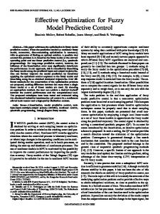
which can be simply expressed as: A(q ± 1 )Y (t) = B(q ± 1 )u(t ± 1) h i h i uT E where Y (t) = N PT , u(t ± 1) = uB . Next, we use the above fuzzy generalized predictive control method to control the boiler-turbine unit system. The control period is eight seconds, with N = 2, Nu = 5, P1 ( j) = 1; P2 ( j) = 1; l1 (i) = :1, l2 (i) = 1 ( j = 1; . . . ; N; i = 1; . . . ; Nu ). Figure 11 shows the response of the fuzzy generalized predictive control method when the magnitude of the PRBS is 0.5. In Figure 11, M1 and M2 are uncorrelated random disturbances (PRBS). In order to check the effectiveness of the fuzzy generalized predictive control method, we apply it to the control of a boiler-turbine unit control, assuming the power
FUZZY GENERALIZED PREDICTIVE CONTROL
97
Figure 11. The responding curves of the MFC system.
Figure 12. A comparison between the MFC system and the normal control system.
demand with 9 MW step increases. As a comparison, the normal boilerfellow-mode unit control system has been simulated as shown in Figure 12. CONCLUSIONS This paper presents an on-line identi® cation approach for MISO fuzzy models that has fairly high accuracy. By using this identi® cation method in a load system of the boiler-turbine unit, an ideal control result has been achieved.
98
Z. HUAGUANG AND L. CAI
A multivariable fuzzy model-based predictive control approach is suggested by means of the principle of Clark’s GPC. The simulation study has shown that this approach has a higher tracking speed to the change of load and a more steady dynamic response to pressure, and it is less sensitive to external disturbances than the conventional boiler-fellow load control system, as seen in Figure 12. By using the proposed interval matrix analysis method the stability of the system can be immediately checked. The MFC also has the advantage that the design procedure and the tuning of the controller parameters are simple to understand and implement. It can effectively control a multivariable non-linear plant with large time-delays and with time-varying parameters. REFERENCES Box, G. E. P., and G. M. Jenkins. 1970. T ime series analysis, forecasting and control. San Francisco: Holden Day. Buck1ey, J. J. 1993. Sugeno type controller, are universal controller. Fuzzy Sets and System 52:299± 303. Cao, S. G. 1997. Analysis and design for a class of complex control systems, Part II: fuzzy controller design. Automatica 33:1029± 1039. Chen Laijiu. 1991. Automatic Control Principle of the T hermal Process and its Application. Beijing, China: Chinese Power Press Company. Clark, D. W., Mohtadi, C., and P. S. Toffs. 1987. Generalized predictive controlPart I: the basic algorithm. Automatica 23: 137± 148. Dai Changguo. 1993. L inear Algebra in Control Systems. China: Southeastern University Publisher. Driakov, D. 1998. Advances in Fuzzy Control. New York: Physica Verlag. Hecker, Oliver. 1997. Non-linear system identi® cation and predictive control of a heat exchanger. Proceedings of the ACC, 3294± 3298. Park, S. W. 1998. Identi® cation and Control Using Dynamic Neural Systems. In 1998 IEEE W orld Congress Neural Networks. 958± 962. Pedrycz, W. 1984. An identi® cation algorithm in fuzzy relational system. Fuzzy Sets and Systems 13:153± 167. Pokorny, Miroslav, and Pavel Osmera. 1997. Fuzzy Models and Controllers Tuning Using Genetic Algorithms. In Seventh IFSA W orld Congress. Prague, 324± 329. Sezer, M. E., and D. D. Siljak. 1994. Stability of interval matrices. IEEE T rans. on Automatic Control 139:368 ± 371. Spooner, Jeffrey T. 1997. Direct adaptive fuzzy control for a class of discrete-time systems. Proceedings of the ACC, 1814± 1818.
FUZZY GENERALIZED PREDICTIVE CONTROL
99
Takagi, T., and M. Sugeno. 1985. Fuzzy identi® cation of systems and its application to modelling and control. IEEE T rans on SMC 15:116± 133. Tanaka, K., and M. Sugeno. 1992. Stability analysis and design of fuzzy control systems. Fuzzy Sets and Systems 45:135± 156. Tong, Shaocheng, Tang, Jiaotao, and Wang Tao. 2000. Fuzzy adaptive control of multivariable non-linear systems. Fuzzy Sets and Systems 111:153± 167. Wang, L. X. 1995. Design and analysis of fuzzy idendi® ers of non-linear dynamic systems. IEEE Trans. Automatic Control 40:111± 117. Wen, C., and Zhang Huaguang. 1998. Input=output linearization for non-linear systems with uncertainties and disturbances using TDC. Cybernetics and Systems 28:625± 634. Xu, Chenwei, and Lu, Yongzai. 1987. Fuzzy model identi® cation and selflearning for dynamic systems. IEEE T rans on SMC 13:153± 167. Zhang Huaguang, and Chen Laijiu. 1991. A technique for handling fuzzy decisionmaking problems concerning two kinds of uncertainty. Cybernetics & Systems 22:681± 698. Zhang Huaguang, Cai Lilong, and Bien Zeungnam. 2000. Multivariable adaptive fuzzy controller for non-linear systems. IEEE T rans on SMC 30: 167± 176.