Proceeding of International Conference on Electrical Machines and Systems 2007, Oct. 8~11, Seoul, Korea
New Configuration of Flux Reversal Linear Synchronous Motor Shi-Uk Chung, Do-Hyun Kang, Jung-Hwan Chang, Ji-Won Kim and Ji-Young Lee Transverse Flux Machine Research Group, Korea Electrotechnology Research Institute, Changwon, Korea E-mail:
[email protected] Abstract —This paper proposes and investigates a new configuration of flux reversal linear synchronous motor(FRLSM). Two models are introduced and analyzed by 2-D finite element method(FEM) for simulation comparisons. Finite element analysis(FEA) shows that the proposed model generates about 239% higher thrust density than the basic model.
10/3τp
g y
U τp
V
W
U
V
W
hm ws
x
Mover
Lbasic
2τp
Stator
(a) Basic model
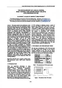
I. INTRODUCTION Conventional linear motion mechanism suffers losses in motion conversion and maintenance problems of wear-prone parts such as gears and ball-screws. Permanent magnet linear synchronous motors(PMLSM) have been successfully adopted as a new mechanism for linear motion system due to less maintenance, better precision, higher acceleration and speed of moving part. In spite of the excellent characteristics of PMLSMs, this solution often results in significant cost increase due to a large amount of permanent magnet(PM) in the stationary part. Therefore, a new design concept needs to be developed to reduce manufacturing cost while retaining some of the advantages of PMLSMs. This paper suggests a cost-effective linear synchronous motor using flux reversal machine(FRM) configuration since FRM adopts a passive rotor where there is no PM or winding. FRM belongs to the class of doubly-salient permanentmagnet machines(DSPMMs) which were originally introduced to incorporate the advantages offered by switched-reluctance and permanent-magnet machines [1], [2]. FRM can exhibit servo quality characteristics when driven by 3-phase sinusoidal vector control [3]. However, most of previous research works related to FRM concentrated mainly on rotary machine, even though there was an attempt to build a flux reversal linear oscillomachine for short stroke application [4]. For long stroke application, FRLSM and its design variants are recently proposed and investigated to show feasibility [5]. II. ANALYSIS MODELS When a conventional FRM is unwrapped, what was the stator now becomes the moving part and the rotor becomes the stationary part. Therefore, passive rotor configuration can be implemented. The conventional 3-phase FRM can be linearized and then modified to have different PM array and winding direction from the conventional FRM as shown in Fig. 1 (a) [5], [6]. Fig. 1 (b) illustrates the proposed design in this paper for higher thrust density. It should be noted that the proposed FRLSM in Fig. 1 (b) adopts middle salient tooth
16/3τp
g y
x
τp ws
U
Mover
Lproposed V
W
hm 2τp
Stator
(b) Proposed model Fig. 1 Configurations of analysis models
between two adjacent PMs, and each PM is of the same polarity. With this unique configuration, the proposed model can reduce flux leakage and generate a large amount of reluctance force, thus increasing thrust density. The proposed model can allow easier PM handling during manufacturing process since unmagnetized PMs can be easily glued to the mover teeth and magnetized afterwards. For simulation comparisons, two models are made to be of the same pole pitch, materials, and electrical ratings. Number of turns per phase is all the same for the given two models, however, coil end turns are not considered in the simulation. All dimensions for the two models are the same except mover length. Major specifications of each model are summarized in Table I.
Symbol τp hm g hs ws R N Br μr Lbasic Lproposed -
- 864 -
TABLE I SPECIFICATIONS OF ANALYSIS MODELS Item Pole-pitch PM thickness Mechanical airgap Stack length Tooth width Phase resistance Number of turns/phase PM residual flux density PM relative permeability Effective mover length of basic model Effective mover length of proposed model Copper wire cross section Mover/stator core material Rated phase current Winding fill factor Coil connection
Value 12.0 4.0 1.0 100.0 12.0 0.169 100 1.2 1.05 224 164 2×1 S23 10 65 WYE
Unit mm mm mm mm mm Ω T mm mm mm A % -
III. FEA RESULTS
2.5
A. Magnetic Field Computation For a steady state, 2-D FEA has been performed using commercial software ANSYS to obtain flux density distribution by applying (1). Back electromotive force (backEMF) can be obtained by (2); detent force, thrust and normal force are calculated by Maxwell stress as in (3) and phase inductance by (4).
2.0
S23
1
μ0
∫
∫
L=
Δλ Δi
B [T]
1.0 0.5
(1)
0.0
(2)
0
10
20
30
40
50
60
20
24
20
24
H [kA/m] Fig. 3 B-H curve of S23
(3)
45
(4)
Basic model Proposed model
30 Detent force [N]
Fx =
r r B = curl A dλ e= dt 1 Bx By dl, Fy = ( By2 − Bx2 )dl 2μ0
1.5
where, B, A, e, λ, Fx, Fy, μ0 Bx, By, L and i denote flux density, magnetic vector potential, back-EMF, flux linkage, thrust, normal force, air permeability, x and y component of airgap flux density, phase inductance, and phase current, respectively. B. Simulation Results Fig. 2 gives no load flux distribution of the analysis models illustrating flux flows in the magnetic circuit. It should be noted that the flux flow of the basic model periodically repeat every 3 slots due to periodic magnetic circuit. This implies that the basic model needs 3 slots to build a 3-phase machine while the conventional FRM needs at least 6 slots for a 3-phase machine due to anti-periodic magnetic circuit. Hence, one can intuitively know that the proposed model also needs only 3 slots for a 3-phase machine since it also shows similar flux distribution to the basic model. It should be also noticed in Fig. 2 (b) that the flux concentrates at the middle salient tooth which is between two adjacent PMs, resulting in thrust increase.
15 0 -15 -30 -45
0
4
8
12
16
Displacement [mm] Fig. 4 Detent force 15 Basic model Proposed model
Back-EMF [V/(m/s)]
10 5 0 -5 -10 -15
0
4
8
12
16
Displacement [mm] Fig. 5 No-load back-EMF of phase U (after skewing) (a) Basic model
(b) Proposed model Fig. 2 No load flux lines of analysis models
The mover and stator material for the given models is S23 whose B-H curve is illustrated in Fig. 3. The detent force appeared in Fig. 4, like in other PM machines, needs to be reduced. Each detent force period in Fig. 4 is equally 8mm (=2/3τp), and 8mm skewing either of stator or mover core can effectively reduce detent force and higher back-EMF harmonics. No load back-EMF of each model induced by phase U after skewing is compared in Fig. 5, showing that the proposed model generates higher back-EMF than the other by 212% in rms value since the proposed configuration
- 865 -
500 Proposed model Basic model
Thrust [N]
400
300
200
100
0
4
8
12
16
20
24
Displacement [mm] Fig. 6 Thrust at rated current (before skewing) 500 Proposed model Basic model
Thrust [N]
400
300
200
100
0
4
8
12
16
20
24
Displacement [mm] Fig. 7 Thrust at rated current (after skewing) 3000 Basic model Proposed model
2700 Normal force [N]
effectively increases flux linkage. For force calculation, 3-phase sinusoidal current is assumed to be applied in phase with each phase back-EMF. Fig. 6 shows thrust of each model at rated current, indicating that the proposed model generates higher thrust with larger ripple than the other due to reluctance force. It should be noticed that the period of thrust ripple is equal to that of detent force, therefore, skewing can reduce thrust ripple as shown in Fig. 7. Normal force and the skewing effect on the normal force are shown in Fig. 8 and 9, respectively, showing that the skewing can also reduce normal force ripple. For the basic model, the thrust ripple can be reduced within 0.6%, and the normal force ripple within 0.2% through skewing. The proposed model generates about 197% higher average thrust than the other with 50% use of PM material while average normal force is about 21% lower. Fig. 10 illustrates phase inductance variations after skewing. All two models experience inductance fluctuation every 24mm(=2τp). However, the basic model displays almost constant phase inductance within 1.4% ripple and the proposed model shows 22.4% ripple. The inductance variation of the proposed model seems to be inevitable like other reluctance assisted PM machines since it introduces middle salient tooth which causes reluctance variation of the magnetic circuit. Further comparison of the average thrust and the average normal force with respect to applied phase current are illustrated in Fig. 11 and 12, respectively. Applied phase current, current density, thrust constant(Kf) defined as the ratio between thrust and applied phase current, thrust density(Fxd) defined as the ratio between thrust and force generating area(=effective mover length×stack length), and thrust ripple are summarized in Table II. The table shows that the proposed model generates 186% higher thrust on average. The proposed model achieves notable increase of 239% in thrust density since it generates higher thrust in smaller force generating area than the basic model. Therefore, the proposed configuration can be made more compact. The normal force of the proposed model increases as applied phase current increases; however, it is relatively lower than the other below about 180% of the rated current as shown in Fig. 12. This implies that the proposed model can alleviate load on linear bearings and further extend linear bearing’s life span. It is especially true for linear motion systems with long constant speed region, since the system only needs to overcome frictional force resistance in the constant speed region. The thrust needed in that region typically ranges below about 30% of motor rated thrust. For the overall characteristics, the basic model exhibits good thrust linearity and very low force ripple and the proposed model generate higher thrust with acceptable force ripple, however it displays nonlinear characteristics in thrust and normal force since it uses a large amount of reluctance force and its magnetic circuit becomes saturated as applied current increases.
2400 2100 1800 1500
0
4
8
12
16
20
24
Displacement [mm] Fig. 8 Normal force (before skewing) TABLE II THRUST CONSTANT AND RIPPLE COMPARISON Kf [N/A] / Fxd [kN/m2] / Ripple [%] Phase Current current [A] density [A/mm2] Basic model Proposed model 16.7 / 1.90 / 2.0 35.6 / 5.40 / 1.1 2.50 1.25 16.8 / 3.90 / 1.0 35.3 / 10.8 / 0.7 5.00 2.50 16.8 / 5.60 / 0.7 34.5 / 15.8 / 0.6 7.50 3.75 16.8 / 7.50 / 0.6 33.2 / 20.2 / 0.8 10.0 5.00 16.8 / 9.40 / 0.5 31.2 / 23.7 / 2.1 12.5 6.25 16.8 / 11.3 / 0.5 28.8 / 26.4 / 3.8 15.0 7.50 16.8 / 13.1 / 0.5 26.6 / 28.3 / 5.0 17.5 8.75 16.8 / 15.0 / 0.5 24.5 / 29.8 / 6.3 20.0 10.0 Average 16.8 / 8.40 / 0.8 31.2 / 20.1 / 2.6
- 866 -
3000
3500
Basic model Proposed model
2400 2100 1800 1500
0
4
8
12
16
Basic model Proposed model
3000 Avg. normal force [N]
Normal force [N]
2700
20
2500 2000 1500 1000
24
0
25
50
75
100
125
150
175
200
Current [%] Fig. 12 Average normal force with respect to applied phase current (after skewing)
Displacement [mm] Fig. 9 Normal force (after skewing)
20 Proposed model Basic model
Inductance [mH]
16
V. [1]
12
[2] 13.3mH(Avg. value)
8
[3] 4.3mH(Avg. value)
4 0
[4]
0
4
8
12
16
20
24
[5]
Displacement [mm] Fig. 10 Phase inductance at rated current in all phases (after skewing)
[6]
600 Proposed model Basic model
Avg. thrust [N]
500 400 300 200 100 0
0
25
50
75
100
125
150
175
200
Current [%] Fig. 11 Average thrust with respect to applied phase current (after skewing)
IV. CONCLUSION This paper proposes and investigates a new configuration of FRLSM to increase thrust density. Typical motor characteristics are obtained by 2-D FEM. Analysis shows encouraging results that the proposed model can provide 239% higher thrust density and relatively lower normal force than the basic model even with the half amount of PM. However, further studies on design and optimization of FRLSM considering dynamic characteristics have yet to be followed both theoretically and experimentally.
- 867 -
REFERENCES
Y. Liao, F. Liang, and T. A. Lipo, “A novel permanent-magnet motor with doubly-salient structure,” IEEE Trans. Ind. Appl., vol. 31, pp. 1069078, Sept.-Oct. 1995. R. Deodhar, S. Anderson, I. Boldea, and T. J. E Miller, “The fluxreversal machine: A new brushless doubly-salient permanent magnet machine,” IEEE Trans. Ind. Appl., vol. 33, pp. 925-934, July-Aug. 1997. I. Boldea, J. Zhang and S. A. Nasar, “Theoretical characterization of flux reversal machine in low-speed servo drives-The pole-PM configuration,” IEEE Trans. Ind. Appl., vol. 38, pp. 1549-1557,Nov.-Dec. 2002. I. Boldea, I. Congxiao Wang, Bin Yang and S.A. Nasar, “Analysis and design of flux-reversal linear permanent magnet oscillating machine,” 33rd IAS Annual Meeting. vol.1, pp.136 – 143, Oct. 1998. S.U. Chung, H. J. Lee and S. M. Hwang, “A Novel Design of Linear Synchronous Motor Using FRM Topology,” in Proc. Compumag ’2007, Aachen, Germany, June 2007, pp. 365-366. T. H. Kim, “A novel design method for flux-reversal machine and characteristics analysis under PWM drives,” Ph.D. dissertation, Hangyang University, Korea, 2004, pp. 109-112.