New Node Integration in TTP/A Networks W. Elmenreich, W. Haidinger, P. Peti, and L. Schneider Institut f¨ ur Technische Informatik TU Vienna, Austria
[email protected] May 14, 2001
Abstract
substantial savings in the labor required to identify new nodes, record serial numbers, calibration factors and data for transducers and reduces the chance of error. Plug and Play functionality is already integrated in the personal computer world. In the fieldbus world, the many existing protocol standards complicate the introduction of consistent and vendor-spanning plug and play systems. There exist software tools working on Profibus, Ethernet [2], CAN and the Foundation Fieldbus [3]. Standard configuration interfaces are presented by the IEEE P1451 [4] standard and the Common Object Request Broker Architecture (CORBA) [5]. The smart transducer interface standard IEEE P1451 supports self-identification via a memory chip physically attached to the node. This chip stores information such as manufacturer name, identification number, device type, and calibration data. This information is called the transducer electronic data sheet (TEDS) [6]. CORBA offers object services (Naming/Trading, Events, etc.) that provide important features to plug and play components. CORBA can be used to implement a consistent interface to whole fieldbus clusters [7] but most smart transducer node resources, especially for low-cost solutions in mass markets, would not suffice for the implementation of CORBA interfaces. A plug and play configuration consists of at least three tasks: to identify the new nodes, to obtain the documentation, and to download the configuration. The second task is assigned to configuration tools that access electronic documentation from databases at a higher level than the fieldbus level. This paper deals with node identification and configuration programming that rely on the fieldbus network level. While new node identification is trivial in many networks it is a difficult task in networks where determin-
The industry calls for fieldbus architectures that allow transducer nodes to be connected into a network in a true “plug and play” fashion. A plug and play configuration consists of at least three tasks: to identify the new nodes, to obtain the documentation, and to download the configuration. This paper deals with node identification and configuration programming for the TTP/A fieldbus. We present a method for identification and configuration of new nodes that is suitable for masterslave fieldbus networks with deterministic timing behavior. The method integrates well with the TTP/A protocol and is implementable in standard TTP/A slave and master nodes. Even though configuration of new components is normally not time critical, our method inherits a deterministic timing behavior from the TTP/A protocol and can be used in parallel with real-time traffic for hot plug and play of new nodes. Keywords: TTP/A, Plug and Play, Smart Sensor, In-System Configuration, Fieldbus, Embedded Systems.
1
Introduction
The installation and configuration of a new network is a difficult task. The system integrator must identify many different nodes, access their specification and integrate them into the network according to their specification. Currently these steps are often performed manually, with high human resource costs and a fair probability of misconfiguration due to human errors [1]. With large data acquisition systems, there is a need for self-identification of nodes. This means that a node can describe itself to the network, thus facilitating an automatic system configuration. This feature provides 1
istic behavior is achieved by master-slave addressing. In case of new nodes, the master doesn’t have knowledge of the identifiers of new nodes, because addressing of such is not supported. If the new nodes are connected one by one, a special command for addressing any new node can be used for assigning a node identifier (baptizing). However when a number of new nodes are expected, a different addressing among the new nodes has to be implemented. The linear search through the name space is often impossible because of the high number of possible nodes (e. g. in the TTP/A protocol nodes own an eight byte identifier, yielding 264 iterations!). For the TTP/A network we searched for (and found) a method that integrates well with the existing TTP/A communication features at an expense of about 64 iterations. The rest of the paper is organized as follows: Section 2 gives an overview on the TTP/A protocol and describes especially the mechanism that is used for the node identification function. Section 3 describes a method for automatic node identification and address configuration called baptizing. Section 4 examines requirements for transducer nodes supporting plug and play. Section 5 discusses the application scope of the presented approach, suggests some optimizations and gives some implementation experiences. Finally, the basic ideas of this paper are summarized in Section 6.
2
munication is organized into rounds. Bus access conflicts are avoided by a strictly TDMA schedule for each round. A round consists of several slots. A slot is a unit for transmission of one byte of data. Data bytes are transmitted in a standard UART format. Each communication round is started by the master with a so-called fireworks byte. The fireworks byte defines the type of round. Slot 0
A multipartner round (see Figure 2) consists of a configuration dependent number of slots and an assigned sender node for each slot. The configuration of a round is defined in the RODL (ROund Descriptor List). The RODL defines which node transmits in a certain slot, the semantics of each individual slot, and the receiving nodes of a slot. RODLs must be configured in the slave nodes prior to the execution of the corresponding multipartner round.
Master-Slave Rounds A master-slave round establishes a connection between the master and a slave for reading/writing monitoring or configuration data, e. g. the RODL information. The action and the memory addressing is encoded in three parameter bytes of a master-slave round. In a further part the addressed data bytes are transmitted between master and slave. FB
a)
MSR
Alias
b)
MSD
Rec#
OP /File #
Check
Time
Record Data Bytes
FB
TTP/A Master
DB0
DB1
DB2
DB3
Check
Time FB MSR MSD Alias Rec # OP File # Check
TTP/A Bus
TTP /A Slave
Slot n DataByte
Figure 2: A TTP/A Multipartner Round
TTP/A is a time-triggered master-slave communication protocol for fieldbus applications that uses a time division multiple access (TDMA) bus arbitration scheme [8].
TTP /A Slave
Slot 3
Time
Basic Principles
TTP /A Slave
Slot 2
DataByte DataByte DataByte
FB Fireworks Byte, sent by master DataByte sent either by master or slave
The TTP/A Protocol
TTP /A Slave
Slot 1
FB
TTP /A Slave
Figure 1: TTP/A Cluster
Fireworks Byte, sent by master Code for Master/Slave Request Code for Master/Slave Data Alias of adressed node Record number of addressed file Operation Code ( Read , Write , eXecute ) File number of addressed node Checksum byte of round
Figure 3: TTP/A Master-Slave Round
It is possible to address up to 254 nodes on a bus. One single node is the active master. This master provides the time base for the slave nodes. The com-
Figure 3 depicts the fixed layout of a master-slave 2
round. A master-slave round consists of two parts. In the addressing part (Figure 3 a)) the action and the memory addressing is encoded in three parameter bytes. In a further part (Figure 3 b)) the addressed data bytes are transmitted between master and slave. The fireworks byte (MSD) is always sent by the master, while the data bytes are either sent by master or slave depending on the action defined in the addressing part. The last byte of each round contains a checksum byte that protects the communication from bus failures. Master-slave rounds have idempotent semantics, thus it is possible to repeat the action in case of communication failures. Thus a master-slave round has a fixed layout. The address scheme is derived from the Interface File System that is explained later in this Section. MP round
MS round
MP round
MS round
Round Descriptor List (RODL): Each node contains at least one and up to six RODLs that contain TDMA schedules for the TTP/A multipartner rounds. TTP/A Configuration File: This file contains at least an 8 bit alias which is the slave’s name within its cluster. Documentation File: This file consists of the node’s unique identifier. This value is assigned invariably to each node. The number identifies the node’s type while the serial number distinguishes nodes of equal type. Optionally this documentation file contains the ASCII text of an uniform resource locator (URL) pointing to a file containing the node’s data sheet. Documentation files are read-only from the master’s viewpoint. To support ultra-low-cost implementations of TTP/A slave nodes, it is also possible to omit the implementation of the file system and hard-code the TDMA schedule for the TTP/A multipartner rounds. Such a node would not respond to any master-slave round and does not support configurability. It is possible to build heterogeneous networks with ultra-lostcost nodes and configurable nodes together but this might have an negative effect for the system overview because the maintenance program is “blind” on the ultra-low-cost nodes.
MP round
Time
Figure 4: Recommended TTP/A Schedule At startup the master uses master-slave (MS) rounds for determining the types of the connected nodes and configuring them. The multipartner (MP) round is intended to establish a periodical, predictable and efficient real-time communication. To support a diagnosis and maintenance access concurrent to the real-time traffic it is recommended to schedule multipartner rounds and master-slave rounds interleaved (see Figure 4).
3
Baptize Algorithm
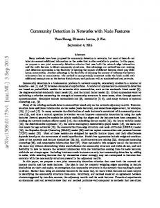
The baptize mechanism performs a binary search on all node identifiers.
The Interface File System For unique addressing of the slave’s internals all relevant data of a TTP/A node like round definitions, application specific parameters and I/O properties are organized into a structure called Interface File System (IFS) [9]. The IFS is structured in a recordoriented format. Each record is addressable separately by master-slave rounds. The Interface File System was introduced for two reasons:
Binary Search The binary search is done by the master. The identification of a new node takes 64 iterations of the algorithm depicted in Figure 5. The master has to keep three 64 bit integer variables, lo, hi and the comparison identifier ci. The values of lo and hi are only needed internally for the calculation of new ci values. The variables lo and hi are initialized to the minimum and maximum value of the expected identifiers (lo:=0x00000000 00000000, hi:=0xFFFFFFFF FFFFFFFF ). During the iterations the values of lo and hi move towards each other until lo equals hi. Then, the identifier of a node is found and the master assigns an alias (different to 0xFF) to this node. The assigning of the new alias is supported by a particular Baptize Operation described later.
• Provide a consistent view of the transducer properties. • Decouple subsystems from the point of view of temporal control. All nodes contain several files that can be accessed over the TTP/A protocol in a unified manner. The minimal set-up for a smart transducer is: 3
New Node Search
a)
FB
Alias
Rec #
OP /File #
MSR
0xFF
0x02
W/0x08
lo:= 0x 0000 0000 0000 0000 hi:= 0x ffff ffff ffff ffff
FB
b)
write 0 into comparison identifier execute compare
any Node Identifier >=0
c) F
No New Node
d)
T
ci:=
e)
hi+lo 2
DB0
DB1
DB2
FB
Alias
Rec #
OP /File #
MSR
0xFF
0x03
W/0x08
lo:=ci
f)
DB0
DB1
DB2
FB
Alias
Rec #
OP /File #
MSR
0xFF
0x02
X/0x08
F any Node Identifier >=ci
T New Node’s Id := ci
Check
Check
DB3
Time Check
Time Check
Node Answer
Time
0x00 Time
FB MSR MSD Alias Rec # OP File # Check
F T
Time
Time
hi:=ci-1
execute compare
ci>=hi
MSD
DB3
Comparison Serial Number
MSD
FB write ci into comparison identifier
Comparison Series Number
MSD
FB
Check
F ci>=hi
T New Node’s Id := lo
Fireworks Byte, sent by master Code for Master/Slave Request Code for Master/Slave Data Alias of adressed node Record number of addressed file Operation Code ( Read , Write , eXecute ) File number of addressed node Checksum byte of round
Figure 6: Identifier Comparison
Figure 5: New Node Identification Algorithm
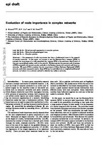
slave’s own hard-coded identifier to the comparison identifier written before.
Identifier Comparison The master performs identifier comparisons as follows:
• The fireworks byte of the second part of the master-slave round initiates a round where all nodes with alias 0xFF whose hard-coded identifier is higher or equal than the comparison identifier write a data frame with content 0x00 in the first slot (see Figure 6 f)). If there are no nodes fulfilling this condition, there are no further bytes sent in this round.
• First, the master sets a lower limit of a node identifier in the nodes to be baptized. The memory for this lower limit is located in the slave node’s IFS described as the comparison series number and the comparison serial number. Henceforth the combination of this value will be called comparison identifier.
The TDMA rounds for the comparison depicted in Figure 6 a)-f) may be interleaved by other multipartner rounds (The blocks a)-b), c)-d), and e)-f) may even be interleaved by other master-slave rounds. Thus it is possible to perform identifier comparisons concurrently with real-time operation of the already integrated nodes.
The initial value for the comparison identifier is (0x00000000,0x000000). Figure 6 a)-d) depicts the bus interactions for setting a comparison identifier with a master-slave round. The master-slave round normally communicates only between the master and a single slave, but in this case there are several slaves addressed, because all unbaptized slaves have the node alias 0xFF.
Baptize Operation When the Series and Serial number of an unbaptized node are known, either derived from the above presented binary search algorithm or entered on a console by a system manager, the master has to change
• Then the master broadcasts an execute command on the comparison series number file (Figure 6 e)). The special action assigned with an execute command on that file/record is the comparison of the 4
4
the node alias of the particular node from unbaptized (0xFF) to its intended alias. Because there may multiple unbaptized nodes in the network, a simple masterslave write access will not success in this task, because the addressing with the alias 0xFF will not be unique. Therefore the nodes have to support a mechanism to overwrite only the alias of the node with a special Series and Serial number.
a)
FB
Alias
Rec #
OP /File #
MSR
0xFF
0x01
W/0x08
b) c)
There are some few requirements for nodes to support an in-system plug and play functionality (There are no extra requirements for all other nodes except that they may not use the node alias 0xFF):
Protocol Requirements The TTP/A protocol includes a generic smart transducer interface with an interface file system (IFS) that offers versatile possibilities for configuration management. The presented approach does not require modifications on the protocol.
Check
Time
FB MSD
0x00
0x00
New Alias
FB
Alias
Rec #
OP /File #
MSR
0xFF
0x01
X/0x08
0xFF
Check
Slave Node Requirements
Time Check
Plug-and-Play configurable nodes must support master-slave rounds with the read, write and execute command and contain at least the following entries in its file system:
Time FB MSR MSD Alias Rec # OP File # Check
Requirements For Baptizing
Fireworks Byte, sent by master Code for Master/Slave Request Code for Master/Slave Data Alias of adressed node Record number of addressed file Operation Code ( Read , Write , eXecute ) File number of addressed node Checksum byte of round
• Documentation File No. 0x3E (read only) containing – Record 0x01: Most significant 4 bytes of node identifier – Record 0x02: Least significant 4 bytes of node identifier
Figure 7: Baptize Operation
• Configuration File No. 0x08 (all records read- and writeable) containing
The Baptize operation includes the setting of the Comparison Identifier to the Series and Serial number of the node desired to baptize. This is done by two master slave write rounds (Figure 6 a)-b) and 6 c)d)). Afterwards the desired new alias is written into the node alias buffer which resides in the same record as the node alias (See Section 4: the node alias buffer occupies byte 0x02, the node alias occupies byte 0x03) by a normal master-slave write round (Figure 7 a)-b)). Because a master-slave write round accesses always a whole record, all four bytes are overwritten. As depicted in Figure 7 a) the values to be written are 0x00, 0x00, the desired node alias, and 0xFF.
– Record 0x01: Byte 0x00 and 0x01 are reserved, Byte 0x02 contains a node alias buffer, Byte 0x03 contains the node alias, must be initialized to 0xFF – Record 0x02: Comparison Series Number, this record has assigned an execute function – Record 0x03: Comparison Serial Number Experiences from TTP/A slave protocol implementations on various platforms [10, 11, 12] have shown that the hardware requirements are moderate. The minimal TTP/A slave protocol needs about 1.5 kB of program memory, 64 bytes RAM and 1 MIPS processing speed (for networks up to 19200 Bit/sec). Because the demanding parts of the node identification algorithm are executed in the master node, the slave nodes stay slim and need just about 10 more bytes of RAM memory for the comparison identifier, the node alias buffer and some state flags.
For setting the alias in the desired node we use an execute command on file 0x08, record 0x01 (Figure 7 c)). This command causes the nodes whose comparison identifier is equal to its hard-coded node identifier to copy the value of the new alias to the alias byte. Thus the node responds to future requests on its new alias. It is the task of the master to keep an account of assigned aliases. 5
Task Initial baptizing (10 nodes) Writing configuration (10 nodes) Identifying a new node during operation Writing configuration for 1 node during operation
Not Optimized 23,77 sec 0,244 sec 5,92 sec 0,079 sec
Optimized 15,97 sec 0,244 sec 5,14 sec 0,079 sec
Table 1: Durations for Node Identification and Configuration
Master Node Requirements
operation we assumed, that each of the 10 integrated nodes periodically sends two bytes of data. Between this communication rounds the parts of a master-slave round are scheduled. The third column in the table depicts the improvements achieved by the acceleration of the baptize algorithm as proposed above. Another application of the approach is automatic new node detection. Figure 5 shows that the algorithm terminates in the first iteration if no new node is present. This property can be used to build a system with automatic new node detection where the master polls periodically for new slaves during real-time operation. Furthermore the algorithm can be used for repairing a cluster where several nodes have assigned the same alias. While such an erroneous configuration is not solvable in a standard TTP/A system, the application of the presented algorithm on such a cluster can reassign different aliases if the concerned nodes support identifier comparison and baptize operations.
The hardware requirements for a typical TTP/A master are between 3.5 kB and 8 kB programm memory and about 1 kB RAM additional to the RAM used by the files. The filesystem must at least contain one RODL (≈ 40 bytes), three special RODLs (12 bytes), documentation file (12 bytes) and the configuration file (16 bytes). The implementation of the baptize mechanism incorporates functions for the binary search, baptize algorithm and communication structures for accessing a configuration database. These functions can easily be supported with the typical TTP/A master hardware.
5
Discussion
The complexity order of the presented approach has the same magnitude as the best possible. However the implementation of the communication between master and slaves has not been optimized for speed. The breakdown of the method in master-slave rounds costs some time, but is justified by:
6
• The configuration phase is normally not time critical.
Conclusion
We presented a method for new node identification and configuration that is suitable for master-slave fieldbus networks with deterministic timing behavior. The method integrates well with the TTP/A protocol and is implementable in standard TTP/A slave and master nodes. Even though configuration of new components is normally not time critical our method inherits a deterministic timing behavior from the TTP/A protocol and can be used in parallel with real-time traffic for hot plug and play of new nodes.
• The presented method integrates well with the TTP/A protocol without changes to the specification. • Interleaving multipartner and master-slave rounds enable hot plug and play during real-time system operation. The presented algorithm can be accelerated by omitting the rewriting of comparison serial or series numbers that did not change from one iteration to the next. For a comparison we defined a test network running at 19200 Bit/sec containing 10 transducer nodes and one master. Table 1 shows the calculated durations for different tasks. For the initial baptizing and configuration writing we assumed that all 10 nodes are new and need to be detected, and the full bandwidth is available for detection. For node detecting and configuring during
Acknowledgments This work was supported in part by the Austrian Ministry of Science, project TTSB and by the European IST project DSoS under contract No IST-1999-11585. 6
References [1] S. K. Raza, B. Pagurek, and T. White. Distributed computing for plug-and-play network service configuration. Network Operations and Management Symposium (NOMS), pages 933–934, 2000. [2] M. T. Hoske. Software tools ease network setup and use. Control Engineering, June 1999. [3] J. Berge and S. Mitschke. Building better open networks using foundation fieldbus and OPC. Sensors Magazine, Feb. 2000. [4] L. H. Eccles. A brief description of IEEE P1451.2. Sensors Expo, May 1998. [5] J. Siegel. CORBA 3: Fundamentals and Programming. John Wiley and Sons, Heidelberg, 1999. [6] K. B. Lee and R. D. Schneeman. Internet-based distributed measurement and control applications. IEEE Instrumentation and Measurement Magazine, 2(2):23–27, June 1999. [7] O. Barheine the usage of chitectures. on Advances many.
and K. D. M¨ uller-Glaser. Concepts for real-time CORBA in time-triggered arProceedings of the 3rd IFAC Workshop in Automotive Control, Karlsruhe, Ger-
[8] H. Kopetz et al. Specification of the TTP/A protocol. Technical report, Technische Universit¨ at Wien, Institut f¨ ur Technische Informatik, March 2000. Available at http://www.ttpforum.org. [9] H. Kopetz, M. Holzmann, and W. Elmenreich. A universal smart transducer interface: TTP/A. Proceedings of the 3rd International Symposium on ObjectOriented Real-Time Distributed Computing (ISORC), March 2000. [10] M. Holzmann and W. Elmenreich. Implementation details on the TTP/A slave protocol. Technical Report 4, Technische Universit¨ at Wien, Institut f¨ ur Technische Informatik, July 1999. [11] R. Obermaisser and A. Kanitsar. Application of TTP/A for the Otto Bock Axon bus. Technical Report 27, Technische Universit¨ at Wien, Institut f¨ ur Technische Informatik, July 2000. [12] P. Peti and L. Schneider. Implementation of the TTP/A slave protocol on the Atmel ATmega103 MCU. Technical Report 28, Technische Universit¨ at Wien, Institut f¨ ur Technische Informatik, August 2000.
7