New Operators for the TURTLE Real-Time UML Profile 2
Christophe Lohr1, Ludovic Apvrille , Pierre de Saqui-Sannes1,3, and Jean-Pierre Courtiat1 1
LAAS-CNRS, 7 avenue du Colonel Roche, 31077 Toulouse Cedex 04, France {lohr,courtiat}@laas.fr 2 Concordia University, ECE department, 1455 de Maisonneuve W., Montreal, QC, H3G 1M8 Canada
[email protected] 3 ENSICA, 1 place Emile Blouin, 31056 Toulouse Cedex 05, France
[email protected]
Abstract. In a previous paper, we defined TURTLE, a Timed UML and RTLOTOS Environment which includes a real-time UML profile with a formal semantics given in terms of translation to RT-LOTOS, and a model validation approach based on the RTL toolset. This paper presents an enhanced TURTLE with new composition operators (Invocation, Periodic, Suspend / Resume) and suspendable temporal operators which makes it possible to model scheduling constraints of real-time systems. The proposed extension is formalized in terms of translation to native TURTLE. Thus, we preserve the possibility to use RTL to check a real-time system model against logical and timing errors. A case study illustrates the use of the new operators.
1 Introduction The Unified Modeling Language provides a general purpose notation for software system description and documentation. The fathers of the OMG standard [7] expected UML to evolve and to be specialized for specific classes of systems. Therefore, they introduced the concept of profile1 to specialize the UML meta-model into a specific meta-model dedicated to a given application domain [10]. Further, several lobbyists at OMG have worked on a profile for real-time systems, published in early 2002 [8] and on the next version of UML, UML 2.0, an enhanced UML with real-time oriented features [12]. Although UML 2.0 opens promising avenues for real-time system modeling, the draft document [12] does not provide enhanced UML with a methodology or a formal semantics. Also, the expression power 1
A profile may contain selected elements of the reference meta-model, extension mechanisms, a description of the profile semantics, additional notations, and rules for model translation, validation, and presentation.
E. Najm, U. Nestmann, and P. Stevens (Eds.): FMOODS 2003, LNCS 2884, pp. 214–228, 2003. © IFIP International Federation for Information Processing 2003
New Operators for the TURTLE Real-Time UML Profile
215
of UML 2.0 in terms of real-time constraints modeling remains limited and compares to the one offered by SDL language [11]. UML’s limitations in terms of real-time system design [10] have also stimulated research work on joint use of UML and formal methods. In [1], we defined TURTLE (Timed UML and RT-LOTOS Environment), a real-time UML profile with a formal semantics expressed in RT-LOTOS [4] and a model validation tool (RTL [9]). TURTLE addresses the structure and behavioral description of real-time systems. A TURTLE class diagram structures a system in so-called “Tclasses”. A Tclass behavior is described with an activity diagram enhanced with synchronization and temporal operators à la RT-LOTOS. Also, unlike UML 1.4, associations between Tclasses are not used for documentation purpose, but are attributed with a composition operator that gives them a precise semantics. The core of what we call “native TURTLE” includes four composition operators (Sequence, Parallel and Synchro, and Preemption). If these four operators enable description of various systems [2] [5], their application to complex mechanisms such as task scheduling remains fastidious. The designer’s burden is important since he or she must describe the details of mechanisms that might advantageously be modeled by high-level and “compact” operators. Suspending tasks is an example of such mechanisms commonly used in real-time systems. The purpose of this paper is to define new high-level operators whose semantics is given in terms of native TURTLE: Invocation, Periodic and Suspend / Resume,. Invocation can be compared to a method call, but applies to inter-task and rendezvous communications through so-called “gates.” Periodic and Suspend / Resume are used to model task scheduling. The paper is organized as follows. Section 2 presents native TURTLE. Sections 3, 4 and 5 introduce the Invocation, Periodic, and Suspend / Resume operators, respectively. Section 6 illustrates the use of these operators. Section 7 concludes the paper.
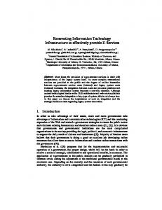
2 The TURTLE Profile 2.1 Methodology The purpose of the TURTLE profile is not to support the entire development of realtime systems. The goal remains “a priori validation” or, in other words, the possibility for a system designer to check a model against errors before the coding phase begins. Fig. 1 depicts an incremental life cycle where a priori validation follows the design and specification phases. A system specification is expressed as a combination of usecase and sequence diagrams. The purpose of the design phase is to produce a class diagram describing the structure of the system under design. The internal behaviors of active classes are modeled by means of activity diagrams. At last, class activity diagrams are combined together and then translated to a RT-LOTOS specification using the algorithms published in [5]. The so-obtained RT-LOTOS specification can be validated using RTL [4]. Also, a correspondence table between actions on the reachability graph and the TURTLE actions is built during the translation process [5]. Thus, system analysis may be done without any knowledge of RT-LOTOS.
216
Christophe Lohr et al. +
(1 ) S p ecifica tio n
U se cases (sy stem e n v iro n m en t)
(3) (2 )
(2 ) D esig n
+ A ctiv ity D ia g r a m (b eh a v io r)
C la ss D ia g ra m (a rch itectu re)
(1 )
S eq u en c e d ia g ra m s (serv ice scen a rio s)
R ea ch a b ility g ra p h (lo g ica l a n d tim in g e rr o r d e tectio n )
(3 ) V alid a tion
Fig. 1. TURTLE-based life cycle
2.2 Extended Class Diagram A TURTLE class diagram is made of “normal” classes and stereotyped ones that we call Tclass. A Tclass is pictorially identified by a “turtle” icon located in the upper right corner of the Tclass symbol. Two Tclasses can synchronize with each other and exchange data using so-called “gates” (Fig. 2a). TURTLE introduces the InGate and OutGate abstract types to distinguish between input and output gates, respectively. The profile enables precise description of synchronization and parallelism relations between Tclasses. An association between two Tclasses must be attributed with the associative class of a composition operator. Operators available with native TURTLE are Sequence, Parallel (Fig. 2b), Synchro, and Preemption. The first three operators make it possible to express tasks that execute in sequence, tasks that run in parallel without communicating and task that synchronize2 on gates. Preemption gives a task the possibility to interrupt another task forever. Tclass Id
Parallel
Composition operator
Attributes
Association
Gates ( Gate, InGate, OutGate ) Methods Behavioral description
T1
T2
(a)
(b)
Fig. 2. Structure of a Tclass (a) and composition between two Tclass (b)
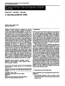
TURTLE extends UML activity diagrams to describe synchronized data sending and receiving, fixed (deterministic) delay, variable (non-deterministic) delay, timelimited offer, and time capture. Fig. 3 depicts the symbols associated with these operators (AD stands for Activity Diagram, the activity sub-diagram following the considered operator). The @ operator stores the amount of time elapsed between the offer of an action and its execution. 2
Synchro must be accompanied by an OCL formula to express “connections” between the
gates involved in the synchronization (E.g.{T1.g1 = T2.g2}).
New Operators for the TURTLE Real-Time UML Profile
g !x ?y
d
t AD
AD
AD
g
t
AD1 AD2
Synchronization Deterministic on g delay
Non-deterministic delay
Time-limited offer
217
g@ d A D
Time capture
Fig. 3. New symbols for activity diagrams
3 Invocation Operator 3.1 Principle Method call is a fundamental feature of object-oriented languages and of UML class diagrams in particular. With native TURTLE, the modeling of method call requires the use of two Synchro operators. Moreover, the activity diagram of the two Tclasses involved in the two synchronizations must check for the validity of data exchange performed during that synchronization. For example, when returning from a method call, data should be exchanged only from the callee to the caller. Such complexity leads us to introduce a novel operator –called Invocation – which makes it possible for a Tclass to insert the activity of another Tclass in its execution flows. Invocation differs from Synchro since the latter characterizes synchronization between two separate execution flows.
Fig. 4. Association attributed with an Invocation operator
Fig. 4 depicts an Invocation associative class. The class is attached to an association starting at Tclass T1 (Invoker) to heading to Tclass T2 (Invoked). Then, we say that T2 can be invoked by T1. Like synchronization, an invocation involves one gate in each class it concerns. Let us call g1 and g2 two gates ofT1 and T2, respectively. Let us assume the OCL formula {T1.g1 = T2.g2} is attached to the relation. Then, when T1 performs a call on g1, T1 must wait for T2 to perform a call on g2. When T2 performs the expected call, data can only be exchanged from T1 to T2, following the direction indicated by the arrow. In other words, parameters can be passed from T1 to T2. T1 is blocked until T2 performs a new call on g2. Call return values and other data can be passed from T2 to T1. Finally, controlled data exchange makes the Invocation operator far more complex that the use of two basic synchronization operators.
218
Christophe Lohr et al.
3.2 Example Fig. 5 depicts a browsing system model. It contains an Invocation between a BrowserWindow and a communication network Comm, playing Invoker and Invoked roles, respectively. The values passed by Invoker are prefixed by “!”. The return value expected by Invoker is prefixed by “?”.
Fig. 5. Use of an Invocation operator in a browsing system
3.3 Translation to Native TURTLE Let us consider a TURTLE modeling whose class diagram contains an Invocation operator. The translation of this modeling to native TURTLE requires modifications at class and activity diagrams level (Fig. 6). Class Diagram. The Invocation operator is substituted with a Synchro operator which
uses the same synchronization gate as the Invocation operator. Activity Diagram. Let us consider Invoker, the Tclass at the origin of the navigation arrow. The call on the gate related with Invocation is replaced by two synchronization calls. First synchronization includes a data offer (“!” prefix) which corresponds to a parameter passing in a method call. Second synchronization consists in waiting for return values (variable prefixed by “?”). The diagram of the Invoked class is not modified.
4 Periodic 4.1 Principle The native TURTLE profile lacks a high-level operator for the description of periodic tasks. Usually, a periodic task executes its main activity in a timely and regular basis. But we propose to introduce a more powerful Periodic composition operator. Indeed,
New Operators for the TURTLE Real-Time UML Profile
219
Periodic makes it possible to specify that a Tclass T2 starts t units of time after another Tclass T1 has started. Also, a Periodic operator attached to an association linking a Tclass to itself describes a “periodic class” i.e. a class whose main activity is periodically started.
Fig. 6. Translating an Invocation into native TURTLE
4.2 Example Let us consider a Periodic associative class attached to an association directed from a Tclass T1 to a Tclass T2 (Fig. 7). T2 is activated 100 units of time after T1’s completion (cf. the keyword “period” in the OCL formula). The keyword “deadline” specifies a maximal execution time for T2. Note that “deadline” is optional. Also, T3 is a periodic class i.e. its activity is started every 100 time units and each activity must have completed within 50 time units.
Fig. 7. Association attributed by a Periodic operator
4.3 Translation to Native TURTLE Be two Tclasses T1 and T2 linked by an association attributed with a Periodic operator. This association is characterized by a navigation arrow from T1 to T2. The proposed translation algorithm inserts a new Tclass named Deferment between T1 and T2, and two composition operators: one Parallel operator between T1 and Deferment and one Sequence operator between Deferment and T2. The value of the delay operator in Deferment’s activity diagram is equal to the value of the “period” keyword in the original diagram. Also, T2 execution time should not exceed the “deadline” value
220
Christophe Lohr et al.
if the latter is specified. If so, a non-intrusive observer is added to the diagram (see the Tclass Observer on Fig. 8). Thus, if T2’s execution time goes beyond the value specified by “deadline” keyword, then the observer preempts T2 and performs a synchronization on gate error. The occurrence of that synchronization is easy to point out at verification step. Indeed, “error” appears as a transition label in the reachability graph of the RT-LOTOS code derived from the TURTLE model.
Fig. 8. Translating the Periodic operator into native TURTLE
5 Suspend/Resume 5.1 Principle The native TURTLE profile defined in [1] includes a Preemption operator which allows a Tclass T1 to abruptly interrupt a Tclass T2 without any possibility for T2 to keep track of its activity and resume later on. Thus, TURTLE lacks a high-level operator to express the possibility for a Tclass to be suspended and subsequently resumed. The Suspend3 operator introduced in this section answers that need. Fig. 9 depicts a Suspend associative class attached to an association directed from a Tclass T1 (Suspender) to a Tclass T2 (Suspended). T2 can be suspended and reactivated by T1. Both operations require a call on gate s (s appears in the OCL formula associated with the relation from T1 to T2). When T1 performs a call on s, T2’s activity is suspended. Then, the next call on s performed by T1 resumes T2. T1 can suspend and resume T2 as many times as needed. 5.2 Example TaskManager (see Fig. 10) implements a basic scheduler which switches TaskA and TaskB, two tasks sharing a same processor resource. Indeed, TaskManager can suspend (or resume) TaskA and TaskB using gates SwitchA and SwitchB, respectively. 3
Suspend is an abbreviation for Suspend/Resume.
New Operators for the TURTLE Real-Time UML Profile
221
When the application starts, both tasks are in the active state. But they are immediately suspended by TaskManager (cf. the calls on SwitchA and SwitchB at the beginning of TaskManager’s activity diagram). Then, TaskA and TaskB are activated one after the other during a quantum of time. The attribute quantumA (resp. quantumB) denotes the quantum of time allocated to TaskA (resp. TaskB).
Fig. 9. Association attributed with a Suspend operator
Fig. 10. Example of a basic scheduler modeled using the Suspend operator
5.3 Suspendable Temporal Operators The native TURTLE temporal operators presented at Fig. 3 assume a universal time. Time continuously progresses and can’t be suspended. Further, it uniformly applies to all components of the system under design. These temporal operators can be used to model, for example, a timer but also to model the execution time of an algorithm. But now, because of the introduction of the Suspend composition operator, a TURTLE Tclass execution might be interrupted. When interrupted, the timer of a class should continue to elapse. Conversely, a temporal operator modeling the execution time of an algorithm should be stopped when the class is interrupted. This leads us to introduce temporal operators that support the concept of time suspension and resume. We call them “suspendable temporal operators”. Fig. 11 depicts the three new suspendable temporal operators: a “suspendable” deterministic delay, a “suspendable” non-deterministic delay, and a “suspendable”
222
Christophe Lohr et al.
timed-limited offer. A small hourglass is added to the original symbols to express the concept of time suspension.
Suspendable deterministic delay
Suspendable non-deterministic delay
Suspendable time-limited offer
Fig. 11. Suspendable deterministic delay, non-deterministic delay, and time-limited offer
Fig. 12 illustrates the use of the deterministic (rectangle box) and non-deterministic (spring) delay operators in their original and “suspendable” versions. The system under design is a DVD player for Personal Computer. First, the DVD player takes a disk and then, it checks it. The access time to tracks depends on the mechanical properties of the device. Mechanical operations cannot be interrupted. Therefore, they are completed independently of any other computations on the PC. Conversely, TaskManager can suspend data decoding which follows synchronization on getData. As a consequence, we associate an hourglass with the deterministic and non-deterministic delays on the left branch of DVD_Player’s activity diagram.
Fig. 12. Example of using basic and suspendable delays
5.4 Translation to Native TURTLE In order to manage the Suspend composition operator, the system should take into account: • The state of all objects that can be suspended. The state is either active or suspended. • The actions that were currently being executed when the suspension was invoked. In particular, the amount of time already consumed by temporal operators should be memorized when a suspension occurs
New Operators for the TURTLE Real-Time UML Profile
223
Detecting the state of an object can be done as follows. If s denotes the gate used by a Tclass T1 to suspend a Tclass T2, the state of T2 can be computed from the number of calls on gate s. The first call on s suspends T2. The second one resumes T2. And so on. In practice, the state of an object can be obtained from the parity of the number of calls performed on s: if the parity is odd, the object is in active state. Otherwise, it is in suspended state. As a consequence, we propose to translate class and activity diagrams as follows. A Synchro operator takes the place of each Suspend operator. The OCL formula of Suspend is not modified because Synchro operates on the same gate s. An association attributed by Synchro is also created between the Suspended Tclass T2 and a new Tclass named ParitySig. T2 and ParitySig synchronize with each other on gates quest and s (Fig. 13). ParitySig checks the parity p of the number of occurrences of action s. Parameter p is odd when T2 is suspended and is even when T2 is active. T2 uses quest to question ParitySig about p (a boolean value exchanged at synchronization time on quest).
Fig. 13. Translation of the Suspend composition operator
T2’s activity diagram is modified as follows. The sub-diagram depicted on Fig. 14 is inserted before each “suspendable” operator symbol. This sub-diagram checks the parity of p. If p is true (even parity) then T2’s activity goes on. Otherwise, T2 waits on gate s for a resume action.
Fig. 14. Testing interruption parity
A second problem is to memorize the action currently executed by T2 when the suspension occurred. A translation scheme is now proposed for every action that needs to be memorized in suspended state.
224
Christophe Lohr et al.
• Synchronization on gates. The synchronization action on a gate a (left part of Fig. 15) is replaced by a sub-diagram involving gates a and s (suspension gate, see right part of Fig.15). On this diagram, the empty diamond represents a nondeterministic choice between gates a and s. When T2 is suspended by a synchronization action on s, it must wait for a resume action modeled by a second synchronization on s.
Fig. 15. Translation of gates for suspendable Tclasses
• Suspendable Temporal intervals. The left part of Fig. 16 depicts a deterministic delay of value dmin, followed by a non-deterministic delay of value dmax-dmin. The two operators in sequence represent a time interval equals to [dmin, dmax]. The temporal interval on the left part of Fig. 16 is translated to the sub-diagram on the right part of Fig. 16. The diamond models a non-deterministic choice between a “non-suspendable” temporal interval and a synchronization action on s. This first synchronization on s suspends T2’s activity. The synchronization on s is limited to DMAX time units. The @ operator stores in variable d the time elapsed since the synchronization on s was offered. When the second synchronization action on s is performed, the new values of DMIN and DMAX are computed: DMIN and DMAX are decremented by d, where d denotes the time consumed within the temporal interval before suspension; and T2 resumes its execution (recursive call).
Fig. 16. Translation of suspendable time intervals
New Operators for the TURTLE Real-Time UML Profile
225
• Time-limited offer. A suspendable time-limited offer is depicted on the left part of Fig. 17. If no synchronization on gate a (left branch) occurs before L units of time, then, the sub-diagram AD2 is executed. Otherwise, AD1 is executed. The translation of the suspendable time-limited offer is depicted on the right part of Fig. 17: a choice is introduced between a “non-suspendable” time-limited offer on gate a (time limit of L) and a synchronization on action s. This first synchronization on s suspends T2’s activity. The @ operator stores in variable d the time at which the suspension occurred (first synchronization on s). When a second synchronization on s is performed, the value of L is computed. Then, T2 resumes its execution (recursive call).
Fig. 17. Translating a suspendable time-limited offer
Note. To translate suspendable temporal operators, we use the @ RT-LOTOS operator to save the time at which suspension and resume actions occur. But the verification algorithms of RTL, the RT-LOTOS toolset, don’t yet support the @ operator. As a consequence, only intensive simulations can be performed from TURTLE models containing Suspend composition operators.
6 Case Study We propose to reuse a case study presented in [6]. The system under design is a protocol entity composed of Sender and Receiver. The purpose of the design depicted on Fig. 18 to model the communication functions of a user terminal and not to validate an end-to-end communication architecture. Therefore, we assume that Sender and Receiver run on the same processing unit. Sender is submitted to the following requirements: 1) The sender must accept a request message from the user every ts time units. 2) The sender must process each message within t ∈ [es, Es] time units before sending it.
226
Christophe Lohr et al.
3) The sender must start processing the message by us time units after the user requested it (us < ts). 4) A message must be sent before xs time units after the request (Es < xs ≤ ts). 5) Receiver is constrained by similar requirements for processing, delivering and accepting received messages: 6) Two received messages are separated by at least tr time units. 7) Processing a received message takes t ∈ [er, Er] time units. 8) A message must be accepted before ur time units since its arrival (ur < tr). 9) A message must be processed and delivered before "xr" time units after its arrival (Er < xr ≤ tr). Fig. 18 depicts three software components implemented on the same processing unit, namely Sender, Scheduler and Receiver. Receiver’s activity diagram is built upon the same principle as Sender’s. Receiver is not described for space reasons. Scheduler implements the following resource allocation politics. A receive request has priority over a sending request. When the processor is allocated to Sender, Scheduler is still ready to give the control to Receiver. Thus, if a receive request arrives, Sender is suspended and Receiver can execute till completion. Scheduler synchronizes on gate send in order to wait for Sender to complete its ongoing activity. Requirements 2, 3 and 4 and their counterparts in 6, 7 and 8 are implemented by three parallel sub-activities within Sender's activity (and similarly within Receiver's activity). Each parallel branch contains an i error action which represents a violation of the th i requirement. Requirements 2, 3, 4 and 6, 7, 8 correspond to constraints related to computation time. Consequently, these constraints are modeled by “suspendable” temporal operators. Conversely, requirements 1 and 5 are not implemented by any processing subject to suspension. Indeed, their implementation use the deterministic delay operator defined in Section 2. Requirements 1 and 5 are checked against violation using the deadline value associated with the Periodic operator (using an observer, as depicted on Fig. 8). Using the TURTLE extensions discussed in this paper dramatically reduces the size of class and activity diagrams. The size of Sender’s activity diagram is divided by four and the size of the class diagram is divided by two in terms of class and relation number. Clearly, the proposed high-level operators make the use of TURTLE more comfortable for complex real-time-system design.
7 Conclusions In [1], we defined TURTLE, a real-time UML profile which improves the OMGbased notation in terms of real-time system modeling, formal semantics, and formal verification. The profile was successfully applied to various case studies, including an industrial application in the framework of the dynamic reconfiguration of software embedded on board satellites [2].
New Operators for the TURTLE Real-Time UML Profile
227
Fig. 18. TURTLE class and activity diagrams of the case study
Despite of its expressiveness, TURTLE was missing high-level operators to model the scheduling of tasks in real-time systems. To address this issue, this paper enhances the TURTLE profile with three composition operators named Invocation, Periodic, and Suspend/Resume. Suspend/Resume leads to introduce the concept of “suspendable” temporal operators in activity diagrams. The proposed extensions are formalized in terms of translation to native TURTLE. This preserves the possibility to use RTL [9] to check a real-time system model against logical and timing errors. As shown in the case study, the use of new these new reduces TURTLE designs complexity. Also, powerful abstractions offered by such operators make them well suited for the modeling and validation of large-scale systems. TURTLE extends class and activity diagrams of UML 1.4. In [3], we defined TURTLE-P, a profile that enhances TURTLE with component and deployment diagrams. TURTLE-P better meets the needs of protocol and distributed architecture modeling and validation because it
228
Christophe Lohr et al.
makes it possible to explicitly model the various execution sites of applications, and communication constraints between theses sites. Again, the TURTLE-P semantics is given in terms of RT-LOTOS.
References 1. Apvrille, L., de Saqui-Sannes, P., Lohr, C., Sénac, P., Courtiat, J.-P.: A New UML Profile for Real-time System Formal Design and Validation in Proceedings of the Fourth International Conference on the Unified Modeling Language (UML’2001), Toronto, Canada, October 1 – 5, 2001. 2. Apvrille L.: Contribution to Dynamic Reconfiguration of Embedded Real-Time Software: Application to a Satellite Telecommunication Environment, Ph.D. dissertation (in French), June 2002. 3. Apvrille L, de Saqui-Sannes, P., Khendek, F.: TURTLE-P : a UML Profile for Distributed architecture Validation (in French). Submitted for publication. 4. Courtiat, J.-P., Santos, C.A.S., Lohr, C., Outtaj, B.: Experience with RT-LOTOS, a Temporal Extension of the LOTOS Formal Description Technique, Computer Communications, Vol. 23, No. 12. (2000) p. 1104-1123. 5. Lohr, C.: Contribution to Real-Time System Specification Relying on the Formal Description Technique RT-LOTOS. Ph.D. dissertation (in French), December 2002. 6. Hernalsteen, C.: Specification, Validation and Verification of Real-Time Systems in ETLOTOS. Ph.D. thesis, Université Libre de Bruxelles, Belgium (1998). 7. Object management Group : Unified Modeling Language Specification, Version 1.4, http://www.omg.org/cgi-bin/doc?formal/01-09-67, 2001. 8. Object Management Group : UML Profile for Scheduling, Performance, and Time, Draft Specification, ftp://ftp.omg.org/pub/docs/ptc/02-03-02.pdf . 9. Real-time LOTOS. http://www.laas.fr/RT-LOTOS . 10. Terrier, F., Gérard, S., Real Time System Modeling with UML: Current Status and Some Prospects, Proceedings of the 2nd Workshop of the SDL Forum society on SDL and MSC, SAM 2000, Grenoble, France, 2000. 11. Tau Generation 2. http://www.telelogic.com/products/tau/index3.cfm . 12. UML 2.0. http://www.u2-partners.org Baldonado, M., Chang, C.-C.K., Gravano, L., Paepcke, A.: The Stanford Digital Library Metadata Architecture. Int. J. Digit. Libr. 1 (1997) 108–121.