AbstractâThis paper proposes a novel technique, known as the variable-height timing window (TW), for rejecting noise in an active source detection system.
666
IEEE TRANSACTIONS ON INSTRUMENTATION AND MEASUREMENT, VOL. 55, NO. 2, APRIL 2006
Noise Rejection Using Variable-Height Timing-Window Technique for Pulse Signals With Variable S/N Ratio Zhaoqing Wang, Bo Chen, Harry H. Cheng, Member, IEEE, Benjamin D. Shaw, Joe Palen, and Ping Feng
Abstract—This paper proposes a novel technique, known as the variable-height timing window (TW), for rejecting noise in an active source detection system. The basic principle of a TW and a methodology of using a microprocessor to dynamically adjust the height of the TW are presented. This variable-height TW technique has been applied to a laser-based detection system (LBDS) for detecting vehicle information on highways. Field-test results of the LBDS showed that the adaptive nature of the proposed TW approach can effectively reject various types of noise under different environmental conditions. This variable-height TW technique can also be used to remove out-of-window noise and suppress the effect of in-window noise in various field environments in which the signal/noise (S/N ) ratio is variable. Index Terms—Laser-based detector, microprocessor control, noise rejection, pulse-signal detection, timing window (TW). Fig. 1.
I. I NTRODUCTION
T
HE EMERGING applications in the detection of physical phenomena enable large-scale cognition and reconstruction of the real world. These applications include but are not limited to areas such as contamination and purification, climate prediction, building structures, transportation and traffic control, and even remote harsh environments. Active source detection systems are more reliable in obtaining signals of real phenomena when applied to unpredictable environments, since detection signals vary within different application environments such as indoor/outdoor, day/night, and even with different testing sites. Most systems utilize a repetitive pulse signal as a source to cut down on energy consumption and to be safer for people. Since these systems utilize a pulsed source, they have intrinsic special features for noise processing. All detection systems are subject to several different types of noise, such as impulse noise [1], interference noise [2], and offset noise for capacitive systems [3]. Any of these types of noise may seriously affect the tolerance, precision, and accuracy of Manuscript received January 23, 2004; revised December 12, 2005. This work was supported by the California Department of Transportation through the Partners for Advanced Transit and Highways Program. Z. Wang, B. Chen, H. H. Cheng, and P. Feng are with the Integration Engineering Laboratory, Department of Mechanical and Aeronautical Engineering, University of California, Davis, CA 95616 USA (e-mail: hhcheng@ ucdavis.edu). B. D. Shaw is with the Department of Mechanical and Aeronautical Engineering, University of California, Davis, CA 95616 USA. J. Palen is with the Office of New Technology and Research, California Department of Transportation, Sacramento, CA 94273 USA. Digital Object Identifier 10.1109/TIM.2006.870329
Principle of a TW.
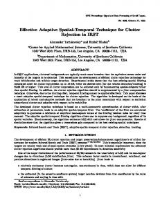
detection and can be classified broadly as either a systematic noise or a random noise [4]. Systematic noise arises from changes in the running conditions, e.g., temperature, humidity, or the aging of sensors. A random noise may include random external sources, random hardware noise, environmental effects, etc. The addition of noise rejection and/or cancellation into any detection system with an ability to change its sensitivity to the source signal would improve its performance and increase its reliability. The example given in this paper is the integration of a variable-height timing window (TW) technique into a laserbased detection system (LBDS) [5] that is developed to detect the velocities and lengths of vehicles on the highway. The system is used outdoors and must adapt to changes in weather and climate, which affects the signal/noise (S/N ) ratio of the detection system through the addition of noise, and changes in the magnitude of the reflected signal. This example shows that the use of a variable-height TW to reject noise makes the detection system not only more adaptive to its environment but also more reliable. In this paper, the basic principle behind TWs is described first. Then, an adaptable noise-rejection method to handle variable S/N -ratio pulse signal using a variable-height TW is presented. Finally, this method is applied to the LBDS, and field-testing results from the highway are presented. II. W ORKING P RINCIPLE OF TW S A TW is just a narrow pulse that is used to extract a small regime from an input source, as shown in Fig. 1. Signals outside
0018-9456/$20.00 © 2006 IEEE
WANG et al.: NOISE REJECTION USING VARIABLE-HEIGHT TIMING-WINDOW TECHNIQUE
667
by modifying the potentiometer in order to pick up the signal and filter out the noise. Since r(t) is dependent on Mi (t) and Mn (t), the measurement of Mi (t) and Mn (t) is extremely important and will be discussed in Section III-B. III. A UTOMATIC C ONFIGURATION OF THE TW
Fig. 2.
Circuit implementation of a TW.
the TW are ignored. In Fig. 1, signal i(t) is the original input pulse signal. Signal r(t) is a variable bottom TW signal that is synchronized with i(t). Signal u(t) is the digital output. Signal r0 (t) is the input reference signal. This simple principle can be used to reject most noises and extract the portion of the signal that is wanted. This paper assumes that all inputs and outputs follow the transistor-to-transistor-logic (TTL) standard in which the highest voltage is 5 V and the lowest is 0 V. If i(t) > r(t), then the output u(t) will be low; otherwise, u(t) will be high. The variable reference pulse signal r(t) should be synchronized to i(t) time t0 . Assume that the period of the signal is T , the magnitude of signal is Mi (t), and the magnitude of noise is Mn (t). Then i(t) = Mi (t) + Mn (t) u(t) =
(1)
(1 − sign (i(t) − r(t))) . 2
(2)
When no signal is input, the output should be high. Mi (t) = 0, and u(t) = 1. This gives r(t) as Mn (t) − r(t) < 0 ⇒ r(t) > Mn (t).
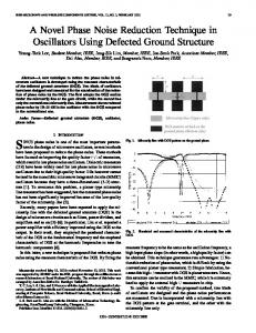
As mentioned in the previous section, the TW pulse r(t) is adjusted by a potentiometer (R). To automatically set the value of R1 to a proper value that makes r(t) have the value expressed in (6), a microprocessor has been introduced into the system to control a digitally controlled potentiometer (DCP). This section introduces the basic working principle of a DCP and how the microprocessor sets a proper DCP value based on step numbers corresponding to the laser signal and noise. A. Digitally Controlled Potentiometer (DCP) A DCP is controlled by two digital inputs in the form of pulses. One input determines whether to increase or decrease the DCP while the other one is a control signal. The resistance of a DCP is quantized into small steps, allowing users to slowly increase or decrease the DCP but not as smoothly as a stepless potentiometer. The amount of steps the DCP can take is DCP dependent. Let us assume n is the total amount of available steps, ni is the current step number, R is the total resistance of the DCP, and R1 is the set resistive value. In Fig. 2, if R1 = 0, then r(t) = 0 V (r0 (t) = 0 V in the TW), and if R1 = R, then r(t) = 5 V, and r(t) can vary from 0 to 5 V. Therefore r(t) =
(3)
In order for the output to be low inside of the TW, t ∈ [t0 + nT, t0 + tw + nT ] and u(t) = 0, we find that r(t) must be Mi (t) + Mn (t) − r(t) > 0 ⇒ r(t) < Mi (t) + Mn (t). (4)
(5)
Typically, we set (6), shown at the bottom of the page. Fig. 2 shows the implementation of a simple TW using a comparator in order to produce a digital output. A potentiometer and a variable reference signal are used to change the height of the TW pulse. Having a static resister would make the TW’s height static. Knowing the magnitude of the input noise and signal, we can then set the appropriate height of the TW (r(t))
Mn (t) + r(t) =
Mi (t) 2
=
� ni =
�
n 10 Mn (t)
∀,
� S , t ∈ [t0 + nT, t0 + nT + tw] 2+ N t �∈ [t0 + nT + tw, t0 + (n + 1)T ] (8)
where ∀ is any value from 0 to n, because r0 is equal to 5 V outside the TW. Therefore � � n S Mn (t) 2 + ni = . (9) 10 N The value r(t) depends on the current step of the DCP (ni ). From (9), we get ni from Mn and the S/N . Therefore, measuring Mn and S/N is a key issue. We will discuss this in the next section.
S Mn (t)(2+ N ) , 2
t ∈ [t0 + nT, t0 + tw + nT ] (6)
when 5V,
(7)
From (6) and (7), we can get the required DCP position (ni ).
From (3) and (4), we can get r(t) ∈ (Mn (t), Mi (t) + Mn (t)) .
5ni R1 ×5= . R n
t ∈ [t0 + tw + nT, t0 + (n + 1)T ]
668
IEEE TRANSACTIONS ON INSTRUMENTATION AND MEASUREMENT, VOL. 55, NO. 2, APRIL 2006
Fig. 3. Block diagram of the configuration circuit.
B. Configuration Procedure The microprocessor sets the proper value of r(t) according to the feedback from the output. Fig. 3 shows the block diagram of the configuration circuit. The microprocessor increases one step of DCP when u1 (t) is high(=1). Thus, we get r(t) as 5 ∗ u1 (t − T ) n (sign (i(t) − r(t)) + 1) . u1 (t) = 2 r(t) = r(t − T ) +
(10) Fig. 4. Configuration algorithm. (a) Procedure for finding Nsi . (b) Procedure for setting DCP.
(11)
Here, the initial condition is r(0) = 0, and 5/n is the step value of the DCP. When the system reaches steady state, t = ts , u1 (ts ) = 0, and the DCP is at a step number of Ns . Rs is the steady-state value of the TW signal r(t) when u1 (t) is zero. Therefore Rs = r(ts ) = r(0) + Ns ∗
5 5 = Ns ∗ . n n
(12)
The height of the bottom line of r(t) is determined by the number of steps that the DCP requires from the initial condition r(0) = 0 to the final proper height. This step count (Nr ) is calculated by two numbers Nsn and Nsi . Nsn stands for the step count of DCP when the bottom line of r(t) increases from zero to the magnitude of noise under the condition of lasersource OFF, while Nsi stands for the step count of DCP when the bottom line of r(t) increases from zero to the magnitude of laser signals. The algorithm of setting the proper step value of r(t) is shown in Fig. 4. Fig. 4(a) is the procedure for finding the step number Nsi , and Fig. 4(b) is the procedure for setting the step number for the TW. When the procedure is initiated in Fig. 4(b), the microprocessor first finds the value of Nsn by increasing the DCP and monitoring the output of the monostable. Then, it finds the value of Nsi in a similar way. Finally, the microprocessor calculates the step number of TW according to the values of Nsn and Nsi . The interrupts of the microprocessor are used to find Nsi and Nsn . The output from the monostable is connected to the interrupt pin of the microprocessor. The microprocessor keeps incrementing the DCP until an interrupt is detected, which occurrs when the output of the DCP goes over the magnitude of noise under the condition of signal-source OFF or over the magnitude of signal with the signal source ON. The number of steps counted is the value of Nsn or Nsi . The value of Nsn is obtained when the laser is OFF, while Nsi is obtained when the laser is ON and the laser beam is unblocked.
The signal i(t) consists of Mi (t) and Mn (t), i.e., i(t) = Mn (t) + Mi (t). The signal Mn (t) is determined by environmental conditions, such as climate, season or the time of day, and electronic noise, which are uncontrollable. The signal Mi (t) is the pure signal generated by the laser source that can be controlled by the microprocessor. When the microprocessor gets the values of both Nsn and Nsi , the proper value of the TW signal r(t) can be obtained by setting Nr = (Nsi + Nsn )/2 The signal r(t) is calculated as follows: � r(t) =
5(Nsi +Nsn ) , 2n
t ∈ [t0 + nT, t0 + nT + tw]
5,
t �∈ [t0 + nT + tw, t0 + (n + 1)T ] . (13)
IV. A PPLICATION OF N OISE R EJECTION U SING M ICROCHIP -C ONTROLLED TW IN LBDS The LBDS project is supported by the California Department of Transportation. The optical and electronic designs for a field prototype have been described in [5] and [6], and a patent for this detection system has been approved by the U.S. Patent Office [7]. This project aims to acquire parameters from moving vehicles such as speed and length. One of the most serious problems in the transportation system is traffic congestion. In order to solve this problem, transportation systems should be more intelligent, which is known as the “intelligent transportation system” (ITS). ITS uses intelligence to enhance the operation of the transportation system based on survey information [8]–[10]. Travel time is a key quantitative parameter for ITS surveillance systems [11]. In addition, travel time is a major indicator of other direct constraints on ITS efficiency: environmental emissions, fuel costs, accident risk, and driver stress. Since travel time is the parameter that travelers most want to know, the detection of this parameter will always be of a very high value. The LBDS is used to measure the speed, which is commonly used as an indicator of the travel
WANG et al.: NOISE REJECTION USING VARIABLE-HEIGHT TIMING-WINDOW TECHNIQUE
Fig. 5.
669
LBDS schematic.
time across a link of highway, and other parameters such as the length and profile of vehicles on the highway. The TW and its algorithms were applied to a recent version of the LBDS. The results of the system showed improvements. Much of the highway field-testing noise was rejected and adjustments to the system were easier and faster compared to older versions [12].
reflected laser light from the asphalt road surface, is very small (about 0.9 µA) [13], [14]. Furthermore, sunlight includes light of the same wavelength as the laser beam. In order to pick up the weak signal from the noisy environment, the TW concept is introduced to eliminate the negative effects of the noise. B. Circuitry Implementation
A. System Architecture of LBDS The working principle of the LBDS is shown in Fig. 5. A laser pulse is projected onto the road and then reflected from the road into the receiver area. Using optical lenses, the reflected laser pulse can be focused onto the photodiode array, and analog signals can be generated. When a vehicle passes under our system, the reflected laser pulse will no longer fall into the active area of the photodiode array. This causes the photodiode array to stop generating analog signals. The LBDS has two pairs of laser–sensor components as shown in Fig. 5. The laser source is a long line beam and the sensor is an avalanche-photodiode (APD) array. When a vehicle passes underneath the LBDS, laser1 beam will be “blocked” first. Laser2 beam will be “blocked” later on. Utilizing the time interval between the blocking of two signals, the velocity of a vehicle can be obtained. Laser1 beam will be “unblocked” as the vehicle continues to pass underneath the system. The laser2 beam will also become “unblocked” at a later time. Based on all signals acquired, the length of a vehicle can be calculated. Two laser sources are used to obtain parameters of vehicles, such as speed and length, as shown in Fig. 5. To avoid any interference between the two laser sources, they are triggered at separate times. One is triggered at the rising edge of the trigger pulse signal, at nT , while the other is triggered at the falling edge of the trigger pulse signal, at nT + T /2. The output signal of the APD array, which is generated by the
To adapt the changing environment, the height of the TW should be configured periodically. The periodical configuration of TW is feasible since the configuration can be automatically initiated by the microprocessor. However, for test purposes, we simply use a button to initiate the configuration procedure. The detection and TW circuitry is shown in Fig. 6. The microprocessor is a Microchip 16F876. The signals from the monostable (74HC123) are introduced into the RB4–RB7 pins of the microprocessor. The microprocessor processes the signals and sends output pulses to the digital potentiometers to adjust their values. A push button BT0 is used to initiate automatic adjustment. The purpose of the microprocessor pins are described as follows. 1) RA0–RA3 (output): CS of the Xicor DCP (XDCP) for channel0–channel3. 2) RA4 (output): INC of the XDCP for all channels. 3) RA5 (output): U/D control of the XDCP for all channels. If it is high, the potentiometer value is increased; otherwise, it is decreased. 4) RB4–RB7 (input from sensors): These pins are connected to the outputs of monostable channel0–channel3. The level changes on the pins will cause an interruption to the microprocessor. The XDCP (X9317U) is introduced into our system. Its resistance can vary from 0 to 50 kΩ. It is a nonvolatile DCP. The device consists of a polycrystalline resistor array of
670
IEEE TRANSACTIONS ON INSTRUMENTATION AND MEASUREMENT, VOL. 55, NO. 2, APRIL 2006
Fig. 6. Microprocessor feedback control loop circuitry.
99 segments and CMOS switches that connect the wiper terminal to any one of the 100 nodes in the array of resistors. The wiper position is defined by data transmitted to the device on the three-terminal serial up/down port. A pulse on the increment pin causes the wiper to move one step to the next wiper position. The direction the wiper moves is defined by the logic state on the up/down pin. A rising edge on the chip-select (CS) pin while the increment pin is high causes the present wiper position to be written into an erasable-programmable read-only memory (EPROM) register. This value is recalled on power up, restoring the last wiper position that was written into the register. The value of the digital potentiometer is increased or decreased by one step whenever a pulse is applied to the INC pin, which is the first pin for increment on XDCP. The RA5 pin from port A of the microprocessor outputs pulses to control the value of the digital potentiometer according to the input data from the output of the monostable. Pins RA0–RA3 are connected to the CS pin of the digital potentiometer to select the chip that is currently being adjusted. RA4 controls the potentiometer increment and decrement when there is a pulse presented to pin INC. A 20-MHz crystal oscillator that is connected to OSC1 provides the microprocessor clock. There are two microprocessor states: adjustment and working. In the adjustment status, the microprocessor adjusts the digital potentiometers to proper positions, while it is monitoring the outputs of the monostables. In the working status, the microprocessor processes signals obtained by electronic circuits. The processing procedure removes some
unwanted signals from the vehicle reflection. The processing implementation is based on the detection of the signal period. The unwanted reflection signals are removed by determining the signal duration. If the signal duration is less than a specified amount, it is considered an unusual signal. C. Software Fig. 7 shows the main flowchart for adjusting the digital potentiometers. The software is written in C language, and this C file is compiled into machine code, which is burned into the microprocessor’s memory. At the beginning of an adjustment, all potentiometers are set to zero. When the BT0 button in Fig. 6 is pushed, the microprocessor that controls the power of lasers and provides the referenced synchronized signals will turn OFF the lasers and perform the algorithm shown in Fig. 4 to find Nsn . When the interrupt to the microprocessor occurs, the value of Nsn is saved in the memory of the microprocessor. This procedure (called preadjustment) finishes in 2–3 s. After preadjustment, the microprocessor will turn ON the lasers. After the BT1 button in Fig. 6 is pushed, the microprocessor sets the potentiometers to 0 again and then increases the resistances of the potentiometers step by step until an interrupt occurs from the corresponding channel. At this point, the value of Nsi will be saved in the memory. After both Nsn and Nsi have been found, the microprocessor will reset the potentiometer to ((Nsi + Nsn )/2) and lock the value in the XDCP’s memory.
WANG et al.: NOISE REJECTION USING VARIABLE-HEIGHT TIMING-WINDOW TECHNIQUE
Fig. 7.
671
Flowchart of XDCP adjustment.
An LED indicator is used to indicate one of the three statuses listed below. 1) Continuous ON: A proper value has been received. 2) Slow flashing: The value of the XDCP may be equal to zero (the system should be adjusted). 3) Fast flashing: The value of the XDCP may be equal to the maximum value of 50 kΩ (the system should be adjusted). The following are functions used in the software. XdcpSet() is the main function that controls the height of the TW. When the adjust button is pushed, this function will be called by the main() procedure. The XDCP is set to the proper value, so that the laser signal can be detected by the digitaloutput circuit. When an interrupt from pins RB4–RB7 is received, an interrupt handler stores the 16-bit time stamp and the port-B status in an array of 24 B. The time stamp is stored in the first two bytes, and the status is stored in the third byte. Therefore, the array can store the time stamps and statuses of eight interrupts. The shorter the interrupt procedure is, the better it is. At least, it should be short enough to be processed before the second interrupt occurs. The interrupter handler is only used to store the states and time. XdcpIntHandling() in Fig. 7 will be called when the interrupt counter is not zero. It reads data from the interrupt status array, determines which channel(s) caused the interrupt, and sets the last 4 bits of xdcp_cs_buffer, which presents the difference between the current status and the last status of port b. If one
bit is different, the corresponding XDCP will be unselected by clearing the bit. D. Experimental Results 1) Results of Signals: The signal input of the LBDS utilizing TWs, which were obtained in our laboratory with a small noise, are shown in Fig. 8. The width of the pulsed signal is about 250 ns, the amplitude is about 2 V, and the noise level is about 0.5 V. At the time when the laser diodes are triggered by the microprocessor, the microprocessor also outputs a negative pulse that drags the low terminals of the potentiometers to the ground level. Then, the wiper output of the potentiometer will form the TW signal r(t). Since the time when the pulsed laser signal appears on the output of the preamplifier and the time when the wiper output of the potentiometer are almost the same, the synchronization between them is guaranteed. The results in Fig. 8 are explained as follows. 1) Fig. 8(a) shows an oscilloscope view of the signal i(t) after the preamplifier. The maximum value of the signal is about Vs , and the minimum value of the noise is about Vn . 2) Fig. 8(b) shows the oscilloscope figure of the reference signal r0 (t), which equals r(t) before adjusting the DCP (DCP = 0). 3) Fig. 8(c) shows r(t) when the DCP is set to Nsn . The bottom of the TW goes up from the position in 2).
672
IEEE TRANSACTIONS ON INSTRUMENTATION AND MEASUREMENT, VOL. 55, NO. 2, APRIL 2006
Fig. 8. Oscilloscope views. (a) i(t). (b) r(t) = r0 (t) before adjustment. (c) r(t) after preadjustment. (d) u(t) after preadjustment. (e) r(t) after adjustment. (f) u(t) after adjustment.
4) Fig. 8(d) shows the view of the output of the comparator after the DCP has been set to Nsn . 5) Fig. 8(e) shows the oscilloscope view of the TW r(t) when the DCP is set to (Nsi + Nsn )/2. 6) Fig. 8(f) shows the view of u(t) after the DCP is set to (Nsi + Nsn )/2. The output u(t) is as high as 5 V beyond the TW. Only the signal in the TW can be obtained. All of the noise is rejected when the magnitude of noise is less than 5 V beyond the TW and the magnitude of noise is less than (Nsi + Nsn )/2 inside of the TW. Fig. 9 shows the signal results acquired from highway field testing. Compared with Fig. 8(e) and (f), the results show that all of the noise has been rejected even in the noisy highway environment.
E. Results of Vehicle Parameters The field-testing results acquired on the I-80 highway in Sacramento, CA, are shown in Fig. 10. The upper portion is the LBDS device mounted on the field. The lower portion is the screen snapshot of the result calculated by the computer, where “v1” is the front speed (in miles per hour) of vehicle, “v2” is the rear speed of the vehicle, and “l” is the length of the vehicle (in meters). We use eight of the available 25 elements of the APD for each side of the LBDS. The 0–7 channels are the elements of the front side, and the 8–15 channels are the elements of the other side. The result shows that the front speed of the detected vehicle is about 74.33 mi/hr, while the rear speed of the vehicle is 74.83 mi/hr, and the length of the vehicle is about 5.16 m. The maximum speed difference among the channels is about 1.3%. The four center channels have almost the same results
WANG et al.: NOISE REJECTION USING VARIABLE-HEIGHT TIMING-WINDOW TECHNIQUE
Fig. 9.
673
Signal results on highway I-80. (a) r(t) after adjustment. (b) u(t) after adjustment.
of the TW is the duration of the signal pulse. Even though the shape of TW, which should be ideally square, is distorted as shown in Fig. 8 due to the CMOS switch of the DCP, the performance of the circuit is still good. Since the bottom line of the TW is variable and can be configured by the microprocessor automatically according to the noise level and the signal level, the proposed noise-rejection method is effectively adaptable to many different applications with heavy noise. ACKNOWLEDGMENT The authors would like to thank Q. Yu, S. S. Nestinger, and C. Zhang for their contributions to the project described in this paper. R EFERENCES
Fig. 10. Field-test results.
due to higher laser-light intensity generated by the Gaussian distribution of the laser source. According to the error analysis in [15], the maximum error is about 2.5% when the speed is about 75 mi/h. V. C ONCLUSION Noise rejection utilizing TWs is very successful in the LBDS. All of the noise beyond the TW was rejected, including the impulse noise caused by the other laser source. The ideal width
[1] S. R. Kim and A. Efron, “Adaptive robust impulse noise filtering,” IEEE Trans. Signal Process., vol. 43, no. 8, pp. 1855–1866, Aug. 1995. [2] A. Bonen, R. E. Saad, K. C. Smith, and B. Benhabib, “A novel optoelectronic interface-circuit design for sensing applications,” IEEE Trans. Instrum. Meas., vol. 45, no. 2, pp. 580–584, Apr. 1996. [3] M. Tavakoli and R. Sarpeshkar, “An offset-canceling low-noise lock-in architecture for capacitive sensing,” IEEE J. Solid-State Circuits, vol. 38, no. 2, pp. 244–253, Feb. 2003. [4] E. Elnahawy and B. Nath, “Cleaning and querying noisy sensors,” in Proc. 2nd ACM Int. Conf. Wireless Sensor Networks and Applications, San Diego, CA, Sep. 19, 2003, pp. 78–87. [5] H. H. Cheng, B. Shaw, J. Palen, J. E. Larson, X. Hu, and K. Van Katwyk, “A real-time laser-based detection system for measurement of delineations of moving vehicles,” IEEE/ASME Trans. Mechatronics, vol. 6, no. 2, pp. 170–187, Jun. 2001. [6] H. H. Cheng, B. Shaw, J. Palen, B. Lin, B. Chen, and Z. Wang, “Development and field test of a laser-based nonintrusive detection system for identification of vehicles on the highway,” IEEE Trans. Intell. Transp. Syst., vol. 6, no. 2, pp. 147–155, Jun. 2005. [7] H. H. Cheng, B. Shaw, J. Palen, J. E. Larson, X. Hu, and K. Van Katwyk, “Non-intrusive laser-based system for detecting objects moving across a planar surface,” U.S. Patent No. 6 404 506, Jun. 11, 2002. [8] C. Sun and S. G. Ritchie, “Individual vehicle speed estimation using single loop inductive waveforms,” J. Transp. Eng., vol. 125, no. 6, pp. 531–538, Nov./Dec. 1999. [9] L. Emerson, “Mobil video surveillance and ramp-metering system,” Intellimotion, vol. 6, no. 2, pp. 10–12, 1997. [10] Y. B. Yim and M. A. Miler, “PATH, TravInfo evaluation,” Intellimotion, vol. 9, no. 1, pp. 1–5, 2001. [11] J. Palen, “The need for surveillance in intelligent transportation systems—Part two,” Intellimotion, vol. 6, no. 2, pp. 1–17, 1997. [12] B. Lin, H. H. Cheng, B. D. Shaw, and J. Palen, “Optical and electronic design for a field prototype of a laser-based vehicle delineation detection system,” Opt. Lasers Eng., vol. 36, no. 1, pp. 11–27, Jul. 2001.
674
IEEE TRANSACTIONS ON INSTRUMENTATION AND MEASUREMENT, VOL. 55, NO. 2, APRIL 2006
[13] H. H. Cheng, B. D. Shaw, J. Palen, Z. Wang, B. Chen, and S. Nestinger, “Non-intrusive methods of characterizing vehicles on the highway,” Integr. Eng. Lab., Dept. Mech. Aeronaut. Eng., Univ. California, Davis, p. 13, Tech. Rep. TR-IEL-2003-103, Jun. 30, 2003. [14] R. Siegel and J. R. Howell, Thermal Radiation Heat Transfer, 3rd ed. Washington, DC: Hemisphere, 1992. [15] Z. Wang, B. Chen, H. H. Cheng, and B. Shaw, “Performance analysis for design of a high-precision electronic opto-mechanical system for vehicle delineation detection on highway,” ASME J. Mech. Des., vol. 125, no. 4, pp. 802–808, Dec. 2003.
Zhaoqing Wang received the M.S. degree in computer engineering and the Ph.D. degree in electrical engineering in 1995 and 1998, respectively, all from Shanghai Jiaotong University, Shanghai, China. From 2001 to 2004, he was a Visiting Scholar in the Department of Mechanical and Aeronautical Engineering, University of California, Davis. He is an Associate Professor and Director of the Instructional Division for Computing Technology, Zhejiang Sci-Tech University, Zhejiang, China. His research interests include network computing, engineering software design, real-time and embedded control system, eXtensible-MarkupLanguage (XML) data processing, Web technology, and Ch and its applications.
Bo Chen received the B.S. and M.S. degrees in electrical engineering from the Zhejiang Sci-Tech University (ZSTU), Zhejiang, China, in 1983 and 1988, respectively, and the Ph.D. degree in mechanical and aeronautical engineering from the University of California, Davis (UC Davis), CA, in 2005. She was an Associate Professor and the Vice Chair of the Department of Electrical Engineering at ZSTU. From 1999 to 2001, she was a Visiting Scholar in the Integration Engineering Laboratory, UC Davis. She currently is a Post Doctor in the Department of Mechanical and Aeronautical Engineering, UC Davis. Her research interests include computer-aided design and analysis, real-time and embedded control, multiagent systems, and intelligent transportation systems.
Harry H. Cheng (M’91) received the M.S. degree in mathematics and the Ph.D. degree in mechanical engineering in 1986 and 1989, respectively, all from the University of Illinois at Chicago. From 1989 to 1992, he worked as a Senior Engineer on information-driven systems at the Research and Development, United Parcel Service, Inc. In 1992, he joined the faculty at the University of California, Davis (UC Davis), where he is currently a Professor and Director of the Integration Engineering Laboratory. He is also a member of Graduate Group in Computer Science and Graduate Group in Applied Mathematics at UC Davis. He is the Chief Architect of an embeddable C/C++ interpreter Ch for script computing, which is being widely used in both the academia and the industry. He is the author or coauthor of more than 110 papers in refereed journals and conference proceedings and is the holder of one U.S. patent. His current research interests include information technology, engineering software design, mobile multiagent systems, information-driven systems, computeraided design and manufacturing, open-architecture mechatronic system integration, and intelligent transportation systems.
Dr. Cheng received a Research Initiation Award from the National Science Foundation, the Procter and Gamble Best Paper Award, and the Waldron Award at the Applied Mechanisms and Robotics Conferences. He received an Outstanding Contribution Award from United Parcel Service, Inc. He participated in revision of the C Standard called C99 through ANSI X3J11 and ISO S22/WG14 C Standard Committees. He is a member of the American Society of Mechanical Engineers (ASME), the IEEE Robotics and Automation Society, and the IEEE Computer Society. He was an Associate Editor of ASME Transactions, Journal of Computing and Information Science in Engineering. He is a member of the International Editorial Advisory Board of the Chinese Journal of Mechanical Engineering—English edition. He was the Chair of the Technical Area of Embedded and Ubiquitous Computing and is currently the Chair of the Technical Area of Computers in Electromechanical Systems of the ASME Division of Computers and Information in Engineering.
Benjamin D. Shaw received the B.S. and M.S. degrees in mechanical engineering from Colorado State University, Fort Collins, in 1981 and 1984, respectively and the Ph.D. degree in mechanical and aerospace engineering from Princeton University, Princeton, NJ, in 1989. From 1988 to 1989, he was a Postdoctoral Researcher at the University of California, San Diego, La Jolla. From 1989 to 1991, he was a Faculty Member in the Mechanical Engineering Department, University of Connecticut, Storrs. Since 1991, he has been a Faculty Member in the Mechanical and Aeronautical Engineering Department, University of California, Davis. His research interests include applied mathematics, combustion, microgravity phenomena, and transportation.
Joe Palen has been doing transportation research for almost three decades, the last one managing over 100 projects in what is now known as “intelligent transportation systems” (ITS). His current focus is on generating transportation data of sufficient quality to provide the “intelligence” behind ITS. He has more than a dozen active projects in detector system development, evaluation, and mounting including inductive signatures, VIPS, DGPS vehicle probes, radar, PTZ cameras, lasers, microelectromechanical systems, evaluation facility development, and mounting system design.
Ping Feng received the B.S., M.S., and Ph.D. degrees in control engineering from Zhejiang University, Zhejiang, Hangzhou, China, in 1982, 1989, and 2001, respectively. In 1999, he was a Visiting Researcher at the University of Applied Science, Lanshut, Germany. From 2003 to 2005, he was a Post Doctor in the Department of Mechanical and Aeronautical Engineering, University of California, Davis. He is currently a Professor and Director of the Department of Automatic Control Engineering, Zhejiang Sci-Tech University, Zhejiang, Hangzhou, China. His current research interests include application of control theory, computer control technology and embedded control systems, smart sensor and intelligent instrument, and intelligent transportation systems.