the correlation peaks owing to the implicit high-pass filter. Fig. 1. Block diagram of the optoelectronic morphological corre- lator. Fig. 2. JTC setup. 2114.
Nonlinear morphological correlation: optoelectronic implementation Pasquala Garcia-Martı´nez, David Mas, Javier Garcı´a, and Carlos Ferreira
An optoelectronic implementation of the nonlinear morphological correlation by use of a thresholddecomposition technique and a joint transform correlator architecture is presented. This nonlinear morphological correlation provides improved image detection compared with standard linear optical pattern-recognition correlation methods. It also offers a more robust detection of low-intensity images in the presence of high-intensity patterns to be rejected. © 1998 Optical Society of America OCIS codes: 070.5010, 250.0250.
1. Introduction
In the field of computer vision image matching plays a fundamental role. With this subject we need, in general, to measure the similarity between two picture functions. Location of a reference signal in a scene may be accomplished by the determination of the position where a function of similarity reaches a maximum or, equivalently, where a given error criterion reaches a minimum. One such error criterion is given by the mean-squared error ~MSE! between two functions. The vast majority of research on image detection has been based on minimizing the MSE, which leads to maximizing the cross-correlation function.1 The MSE criterion has been shown to be optimal if the signal to be detected is corrupted with additive Gaussian noise,2 but for deviations from this Gaussian assumption other error criteria are more robust. One such criterion, widely used in signal processing and template matching, is the mean-absolute error ~MAE! ~see Ref. 3, for example!. In detection tasks the MAE criterion has two key advantages over the MSE criterion4: ~a! the MAE increases faster than the MSE when the reference is displaced from its optimal matching position and ~b! the MAE criterion is more robust in the presence of non-Gaussian noise distributions and, in particular,
` pThe authors are with the Departament Interuniversitari d’O tica, Universitat de Vale`ncia, Calle Dr. Moliner 50, 46100 Burjassot, Spain. Received 23 May 1997; revised manuscript received 8 December 1997. 0003-6935y98y112112-07$15.00y0 © 1998 Optical Society of America 2112
APPLIED OPTICS y Vol. 37, No. 11 y 10 April 1998
in the presence of outliers ~such as salt and pepper noise!. Maragos in Ref. 4 defined a nonlinear correlation named the morphological correlation ~MC! that is optimal when using the MAE criterion, i.e., minimizing the MAE is equivalent to maximizing the MC. The MC provides better performance and higher discrimination capabilities in pattern-recognition tasks in comparison with linear correlation.4,5 This correlation is called morphological since it is defined in terms of erosionlike minimum correlation-pattern values, so it has some connection with mathematicalmorphology theory.4 –7 A straightforward implementation of gray-scale mathematical morphology and rank-order filtering requires ordering of the elements in the kernel window. This time-consuming operation can be avoided by use of the threshold-decomposition concept and from taking advantage of the stacking property.8 –11 Since these methods use linear operations it is possible to perform optical implementations of these operations if we take advantage of the inherent parallelism of optics.12–15 In this paper we present an advantageous optoelectronic implementation of the MC. New advantages in pattern recognition are obtained as a result of the nonlinearity property of the MC. We compare both the optical linear correlation and the MC to demonstrate the true potentials of this nonlinear detection technique when optically implemented. In Section 2 we recall the definition of the MC on the basis of the threshold-decomposition concept. In Section 3 we present a novel, to our knowledge, experimental system for obtaining the MC. In Section 4 experimental results are presented, and in Section 5 we outline the conclusions.
2. Morphological Correlation
Let us consider two real-valued two-dimensional signals represented by f ~z, h! and g~z, h!, where ~z, h! [ Z 2. For the sake of clarity we consider that both f and g are defined in the discrete domain, although the formal definitions can be done in the continuous domain. Assume that f is a pattern to be detected in g. For finding which shifted version of f best matches g, a standard approach has been to search for the shift lag ~x, y! that minimizes the MSE,4 defined as MSE~ x, y! 5
(
z,h[W
@ g~z 1 x, h 1 y! 2 f ~z, h!#2, (1)
over some subset W of Z 2. According to Ref. 4 and under certain assumptions,1 this matching criterion is equivalent to maximizing the linear cross correlation between g and f: ggf ~x, y! 5
(
g~z 1 x, h 1 y! f ~z, h!.
z,h[W
(2)
Other error criteria are more robust when the signal to be detected is corrupted with noise patterns that are different from additive Gaussian noise.4 One such criterion is the MAE, defined as MAE~ x, y! 5
(
z,h[W
u g~z 1 x, h 1 y! 2 f ~z, h!u.
(3)
As in Ref. 4 and under certain assumptions,5 minimizing the MAE is equivalent to maximizing the nonlinear cross correlation: mgf ~x, y! 5
(
z,h[W
min@ g~z 1 x, h 1 y!, f ~z, h!#,
(4)
which corresponds to the definition of the MC given by Maragos.4 The term “morphological correlation” is used because the morphological autocorrelation of f ~x, y!, mff ~x, y! is equal to the area under the signal obtained by erosion of the function f ~x, y! by a twopoint structuring element $~0, 0!, ~x, y!%.4 Analogously to morphological and rank-order operations, MC implementation can be performed by use of the threshold-decomposition concept.10 The threshold decomposition of a quantized gray-level image f ~ x, y! is defined as Q21
f ~x, y! 5
( f ~x, y!,
(5)
q
q51
where fq~x, y! 5
H
1 if f ~x, y! $ q . 0 otherwise
(6)
Q21
mgf ~x, y! 5
Q21
(m
gq fq
q51 Q21
5
~x, y! 5
(g
gq fq
~x, y!
q51
( @g
q
, fq#~ x, y!,
(8)
q51
where Q is the number of gray levels of the images, ggqfq~x, y! is the linear cross correlation between the qth binary slices fq and gq, and the w denotes the linear correlation operation, which can be realized optically. To obtain Eq. ~8! it has been taken into account that, for binary qth thresholded input signals, the MC mgqfq~x, y! and the linear correlation ggqfg~x, y! coincide @see Eqs. ~2! and ~4!# because the minimum of two binary numbers is equal to their product. Thus the result expressed by Eq. ~8! together with the ability of optical systems to perform linear correlations and the computational cost of the digital calculation of Eq. ~4! encouraged us to implement the MC optically. We perform an optoelectronic implementation of a nonlinear correlation for object detection; however, because of the closeness of MC to morphological erosion, the MC has the term morphological in its definition.4 Anyway, it is difficult to fulfill gray-scale mathematical-morphology properties.3,6 Note that sometimes in the literature gray-scale morphological erosion and dilation functions are denoted as MC’s.8 In this paper MC refers to the definition reported in Ref. 4. 3. Experimental System
The first step is to obtain the optical correlations between the different thresholded images gq and fq. This can be accomplished in a programmable morphological processor15,16 or in a conventional VanderLugt correlator.17 However, in these processors the optical intensity output uggqfqu2 is obtained instead of the amplitude-correlation output gfq gq needed in Eq. ~8!. This drawback, as is explained below, can be overcome by use of a joint transform correlator ~JTC! scheme.18 To recall the operation of a JTC, let f ~ x 1 x0, y! and g~x 2 x0, y! be the reference and the input scene objects centered at ~2x0, 0! and ~ x0, 0!, respectively. The joint power spectrum ~JPS! is JPS~u, v! 5 uF~u, v!exp@if~u, v!#
Now, for any ~x1, y1! and ~x2, y2!,
1 G~u, v!exp@2if~u, v!#u2
min@ g~x1, y1!, f ~x2, y2!#
5 uF~u, v!u2 1 uG~u, v!u2
Q21
5
expressed by use of the threshold decomposition of g and f. It turns out to be the sum over all amplitudes of the linear correlations between thresholded versions of g and f at every gray-level value q ~Ref. 5!:
( min@ g ~x , y !, f ~x , y !#, q
1
1
q
2
2
(7)
q51
because gq and fq are binary signals. Then the MC between g and f, mgf ~x, y!, can be
1 F*~u, v!G~u, v!exp@2i2f~u, v!# 1 F~u, v!G*~u, v!exp@i2f~u, v!#,
(9)
where f~u, v! 5 2puxoy~lf !, with f the focal length of the Fourier transform ~FT! lens and l the wavelength 10 April 1998 y Vol. 37, No. 11 y APPLIED OPTICS
2113
Fig. 2. JTC setup.
the optical MC is the calculation of each binary slice JPS, JPSq. The obtained distributions are added as Q21
Fig. 1. Block diagram of the optoelectronic morphological correlator.
JPS¥~u, v! 5 5
of the illuminating coherent light. F~u, v! and G~u, v! represent the FT’s of f and g, respectively. The next Fourier transformation yields
( JPS ~u, v! q
q51 Q21
(
q51 Q21
1
1 @ g , f #~x 2 2xo, y! (10)
The third term in Eq. ~10! is the cross correlation between g and f centered at the coordinates ~2xo, 0! at the JTC output plane. The disadvantage of this system is the need for a high space–bandwidth product because both the scene and the reference object share the input plane. Moreover, an adequate separation between the object and the scene is needed to avoid overlapping effects in the correlation output plane. However, the robustness to optical misalignment and the ease of constructing the JTC offer advantages in real-time implementation with respect to VanderLugt correlators.19 For obtaining the MC, as Eqs. ~9! and ~10! are connected by a Fourier transformation and this is a linear operation, the sum of Eq. ~8! is performed on the JPS, which is the actual intensity output detected in the intermediate step of the JTC. So the amplitude-addition requirement in Eq. ~8! implies that the JTC architecture is essential for obtaining the MC optically. Note that the phase is coded as intensity in the JPS; hence no phase information has been lost. A final FT will provide the MC. The whole process is sketched in Fig. 1. So, as mentioned above, the first step in obtaining 2114
APPLIED OPTICS y Vol. 37, No. 11 y 10 April 1998
2
q
( F *~u, v!G ~u, v!exp@2i2f ~u, v!# q
q
q
( F ~u, v!G *~u, v!exp@i2f ~u, v!#. q
q51
^$JPS~u, v!% 5 @ f , f #~x, y! 1 @ g , g#~x, y!
( uG ~u, v!u
q51
q51 Q21
1
1 ) @ f , g#~x 1 2xo, y!.
Q21
uFq~u, v!u2 1
q
q
(11)
Comparison with Eq. ~8! shows that the FT of the third term gives the MC between the scene g~x, y! and the reference f ~x, y! object. In our implementation we use a JTC, as shown in Fig. 2. The thresholded versions of the input and the reference are displayed side by side in an Epson liquid-crystal SLM. The JPSq of each binary slice is recorded with a CCD camera and stored. The JPS¥ is obtained as a summation @Eq. ~11!# and readdressed to the SLM by a frame grabber. The final MC is achieved at the joint transform output plane. The generation of threshold components and the addition operation are done electronically. The system will perform several optical-to-digital and digital-to-optical transformations: The camera will introduce quantization and electronic noise effects. The SLM will introduce, in principle, nonlinearities in amplitude conversion and a bias owing to its limited contrast. Nonlinearities in the SLM can be avoided by proper calibration.20 The limited contrast will result in an increased dc term in the FT plane. To make efficient use of the dynamic range of the camera it is necessary that saturation of the dc term occur for proper recording of the high frequencies of the JPS. The main effect of this saturation is to increase the sharpness of the correlation peaks owing to the implicit high-pass filter.
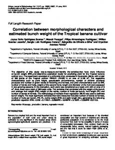
Fig. 3. Two different joint input images, both with an input scene and a reference object.
Other effects, such as electronic noise in the camera, the frame grabber, and the SLM, will not have significant effects on the final result of our experiment. This is because, for obtaining a sharp correlation peak, the main feature of the JPS is the geometrical shape of the interference fringes between the object and the scene. Proper scaling of the JPS and the above-mentioned saturation of the camera
will allow distinct recording of the fringes. Moreover, the addition of the JPS’s will tend to cancel the random noise. With regard to the speed of the process, the bottleneck in the system is the video rate of the SLM ~25 framesys in our case!, which is used to display both the binary slices and the addition of the JPS, which requires a two-cycle JTC architecture. The speed of
Fig. 4. Experimental output plane containing the optical correlations of the scene shown in Fig. 3~a!. The three-dimensional plots cover the area around the correlation peaks. ~a! Linear correlation g. ~b! MC m. 10 April 1998 y Vol. 37, No. 11 y APPLIED OPTICS
2115
Fig. 5. Experimental output plane containing the optical correlations of the scene shown in Fig. 3~b!. The three-dimensional plots cover the area around the correlation peaks. ~a! Linear correlation g. ~b! MC m.
the system can be significantly increased if it is split in two subsystems, each composed of a SLM, a Fourier transforming lens, and a CCD camera. In the first subsystem the input is the threshold decomposition of the joint input scene. The addition of the JPS obtained from it is fed into the second subsystem to produce the final MC. The performance of the whole setup is determined by the first subsystem, as the binary slices must be displayed in sequence for every gray level in the joint input image ~typically 256 levels!. Owing to the fact that the slices are binary, the speed in this step can be increased dramatically by use of a ferroelectric liquid-crystal SLM. The theoretical limit for the switching frequency of these devices is approximately 20 kHz,21 which would, in principle, permit the sequential display of the entire binary-slice set in approximately 10 ms. Nevertheless, for realistically sized images the data transfer among the different devices in the system for such a fast frequency would be greater than is currently possible. Moreover, the contrast of the ferroelectric liquid-crystal SLM would be extremely low. When dealing with systems that have been experimentally demonstrated,22,23 more 2116
APPLIED OPTICS y Vol. 37, No. 11 y 10 April 1998
than 1000 binary images per second can be displayed properly. This rate would permit the display of the entire threshold decomposition for a 256-gray-level image in approximately 250 ms. The final task for the first subsystem consists of carrying out the addition of the JPS of the binary slices. This can easily be accomplished if the integration time of the camera is set to the time needed to display the whole set of binary slices. Thus the addition operation is obtained automatically at no extra time cost. Note that the integration time can vary from 10 ms at the theoretical maximum speed to 250 ms in a real case. This integration-time range is available for most commercially available CCD cameras. The second subsystem takes the gray-scale addition of the JPS, so the SLM in this second step must be capable of handling gray-level images. This second step is performed only once per MC, so the speed is not critical. A twisted nematic SLM that can work at video rates can do the work without significantly increasing the processing time. In summary, making use of today’s technologies means that the whole system could perform approximately four full
MC’s per second for input images with 256 gray levels. The speed can be further increased by a reduction of the number of gray levels in the input.
ject, thus producing a false alarm @Fig. 5~a!#. With the MC a threshold lower than 50% is enough to reject the high-intensity object @Fig. 5~b!#.
4. Experimental Results
5. Conclusions
For demonstrating the advantages of the MC for image detection optical experiments have been performed by use of the above-described JTC. We compare the linear correlation and the nonlinear MC in our optical experiments. In the SLM a joint input image composed of the input scene in the upper half and the reference object in the lower half is displayed. The input scene contains two objects on a dark background. A replica of the object to be recognized ~target!, used as the reference, is placed below the corresponding input scene. The objects in the joint input image have 16 gray-level values, and the outer shapes are identical. This implies that we are adding the JPS’s of 16 binary input scenes for performing the MC. Moreover, the saturation effect of the camera induces the enhancement of the high-frequency components. However, in spite of the bias building ~dc plus low-spatial-frequency content! carried with each joint transform pattern, their addition, as performed electronically, does not involve any drawback in the recording of all the frequency components. We simply add the JPS’s and rescale the sum JPS¥ before displaying it in the SLM for the next step. Two different cases are considered, as shown in Figs. 3~a! and 3~b!. In Fig. 3~a! the objects of the input scene have different gray-level distributions, but their total energies are similar. Figure 3~b! shows an input scene with two objects identical in shape and structure but very different in total energy. For convenience the objects have been labeled with capital letters. In the experiments we compare the results obtained for the detection of an object with both linear correlation and the MC. In the cases depicted in Figs. 3~a! and 3~b!, the objects to be detected are those labeled A and C, respectively. For the case shown in Fig. 3~a!, the correlation peaks obtained for the two objects A and B are comparable in height when the linear correlation is performed and are therefore hardly distinguishable @see Fig. 4~a!#. With the MC a threshold close to 50% is enough to discriminate the correlation peak corresponding to target A from that corresponding to object B @see Fig. 4~b!#. The second experiment involves pattern recognition among different-intensity objects. In Fig. 3~b! target C is the low-intensity object to be detected against a high-intensity one, D. Since conventional correlation is proportional to intensity and sensitive to shape variations that do not exist in this case, any linear filtering will produce a higher peak for the brighter object and so will not be able to distinguish the dark object in the presence of the bright one. On the other hand, MC, owing to its nonlinearity, provides a higher peak for the dark object, so correct detection is obtained. The linear correlation and the MC peaks for this case are shown in Fig. 5. It is clear that linear correlation detects the brightest ob-
In conclusion, we have optically implemented the nonlinear MC using threshold decomposition and a JTC architecture. This nonlinear technique provides improved detection compared with standard linear correlation methods. The main result of this nonlinear operation is the provision of efficient lowintensity image detection in the presence of other high-intensity patterns. The nonlinearity of the process provides selective luminosity-level image detection that could result in useful applications in recognition tasks. D. Mas acknowledges a grant from the Generalitat Valenciana. This study has been supported by the Spanish CICYT ~Comisio´n Interministerial de Ciencia y Tecnologı´a!, project TAP96-1015-C03-03. We thank Tomasz Szoplik for many useful remarks. References 1. R. O. Duda and P. E. Hart, Pattern Classification and Scene Analysis ~Wiley, New York, 1973!, Chap. 7, p. 279. 2. G. L. Turin, “An introduction to matched filters,” IRE Trans. Inf. Theory IT-6, 311–329 ~1960!. 3. E. R. Dougherty and J. Astola, An Introduction to Nonlinear Image Processing, Vol. TT16 of SPIE Tutorial Text Series ~SPIE Press, Bellingham, Wash., 1994!. 4. P. Maragos, “Morphological correlation and mean absolute error,” in ICASSP-89: 1989 International Conference on Acoustic, Speech and Signal Processing ~Institute of Electrical and Electronics Engineers, New York, 1989!, Vol. 3, pp. 1568 – 1571. 5. P. Maragos, “Optimal morphological approaches to image matching and object detection,” paper presented at the Second International Conference on Computer Vision, Tampa, Florida, 5– 8 December, 1988. 6. J. Serra, Image Analysis and Mathematical Morphology ~Academic, London, 1982!. 7. P. Maragos and R. W. Schafer, “Morphological systems for multidimensional signal processing,” Proc. IEEE 78, 690 –710 ~1990!. 8. P. Maragos and R. W. Schafer, “Morphological filters. Part I: their set-theoretic analysis and relations to linear shiftinvariant filters,” IEEE Trans. Acoust. Speech Signal Process. ASSP-35, 1153–1169 ~1987!. 9. P. Maragos and R. W. Schafer, “Morphological filters. Part II: Their relations to median, order-statistic, and stack filters,” IEEE Trans. Acoust. Speech Signal Process. ASSP-35, 1170 –1184 ~1987!. 10. J. P. Fitch, E. J. Coyle, and N. C. Gallagher, Jr., “Median filtering by threshold decomposition,” IEEE Trans. Acoust. Speech Signal Process. ASSP-32, 1183–1188 ~1984!. 11. P. D. Wendt, E. J. Coyle, and N. C. Gallagher, “Stack filters,” IEEE Trans. Acoust. Speech and Signal Process. ASSP-34, 898 –911 ~1986!. 12. E. Ochoa, J. P. Allebach, and D. W. Sweeney, “Optical median filtering using threshold decomposition,” Appl. Opt. 26, 252– 260 ~1987!. 13. J. M. Hereford and W. T. Rhodes, “Nonlinear optical image filtering by time-sequential threshold decomposition,” Opt. Eng. 27, 274 –279 ~1988!. 14. R. Schaefer and D. Casasent, “Optical implementation of gray 10 April 1998 y Vol. 37, No. 11 y APPLIED OPTICS
2117
15. 16.
17. 18. 19.
scale morphology,” in Nonlinear Image Processing III, E. R. Dougherty, J. Astola, and C. G. Boncelet, eds., Proc. SPIE, 1658, 287–296 ~1992!. J. Garcı´a, T. Szoplik, and C. Ferreira, “Optoelectronic morphological image processor,” Opt. Lett. 18, 1952–1954 ~1993!. M. Gedziorowski and J. Garcı´a, “Programmable optical digital processor for rank-order and morphological image processor,” Opt. Commun. 119, 207–217 ~1995!. A. VanderLugt, “Signal detection by complex spatial filtering,” IEEE Trans. Inf. Theory IT-10, 139 –145 ~1964!. C. S. Weaver and J. W. Goodman, “A technique for optically convolving two functions,” Appl. Opt. 5, 1248 –1249 ~1966!. X. J. Lu, F. T. S. Yu, and D. A. Gregory, “Comparison of VanderLugt and joint transform correlators,” Appl. Phys. B 51, 153–164 ~1990!.
2118
APPLIED OPTICS y Vol. 37, No. 11 y 10 April 1998
20. C. Soutar, S. E. Monroe, Jr., and J. Knopp, “Measurement of the complex transmittance of the Epson liquid crystal television,” Opt. Eng. 33, 1061–1068 ~1994!. 21. G. Moddel, “FLC spatial light modulators,” in Spatial Light Modulator Technology: Material, Devices and Applications, U. Efron, ed. ~Marcel Dekker, New York, 1995!, Chap. 6, pp. 347–349. 22. B. Noharet, H. Sjo¨berg, and R. Hey, “Fast portable optical information processing,” paper presented at the EuroAmerican Workshop: Optoelectronic Information Processing, Sitges, Barcelona, Spain, 2–5 June, 1997. 23. J. P. Karins, S. A. Mills, J. R. Ryan, and R. Barry Dydyk, “Performance of a second-generation miniature ruggedized optical correlator module,” Opt. Eng. 36, 2747–2753 ~1997!.