Eötvös Loránd University and MTA SZTAKI,. Budapest, Hungary. Abstract—Sensor fusion is an important part of modern cyber- physical systems that observe ...
2016 IEEE International Conference on Systems, Man, and Cybernetics • SMC 2016 | October 9-12, 2016 • Budapest, Hungary
Novel Methods for Image-Guided ToF Depth Upsampling Iv´an Eichhardt
Zsolt Jank´o
Dmitry Chetverikov
E¨otv¨os Lor´and University and MTA SZTAKI, Budapest, Hungary
MTA SZTAKI, Budapest, Hungary
E¨otv¨os Lor´and University and MTA SZTAKI, Budapest, Hungary
Abstract—Sensor fusion is an important part of modern cyberphysical systems that observe and analyse real-world environments. Time-of-Flight depth cameras provide high frame rate low-resolution depth data that can be efficiently used in many applications related to cyber-physical systems. In this paper, we address the critical issue of upsampling and enhancing the low-quality depth data using a calibrated and registered highresolution colour image or video. Two novel algorithms for image-guided depth upsampling are proposed based on different principles. A new method for video-guided upsampling is also presented. Initial test results on synthetic and real data are shown and discussed.
I. I NTRODUCTION Time-of-Flight (ToF) depths cameras [12], [11], [26] are compact depths measuring devices that provide depth and reflectance data at video rates. Due to their small weight, low consumption and lack of mobile parts, ToF cameras are widely used in numerous application areas [14] such as robot vision [18] and navigation [34], [38], simultaneous localization and mapping (SLAM) [23], [13], 3D reconstruction [19], [33], 3DTV [36], [31], human-computer interaction (HCI) [15], [29] and computer graphics [20], [27]. As discussed in the recent survey [5], the features of depth cameras are complementary to those of passive stereo. The most widely used capability of the cameras is that they greatly simplify the solution of a key problem of 3D vision, the separation of foreground from background. For example, Kinect 2 incorporates a ToF camera that can be used for realtime 3D reconstruction and SLAM [33], the tasks that require fast and efficient foreground-background separation. The main drawbacks of depth cameras are the low resolution and signal-to-noise ratio of the measured depth. In particular, depth edges at surface discontinuities are critical areas where depth measurements tend to be invalid or missing [11]. Since the introduction of ToF cameras, significant research and development effort has been invested into improving the quality of depth data by depth upsampling and enhancement fusing multiple or additional sensor data. The study [10] proposes a classification of depth upsampling approaches into three groups, namely ToF–stereo fusion [24], [16], temporal and spatial upsampling with multiple measurements [8], [33], and depth upsampling with single optical image or video [5], [10], [36]. In this paper, we address the
978-1-5090-1897-0/16/$31.00 ©2016 IEEE
last of the three problems and propose and test novel methods for image and video-guided improvement of resolution and quality of ToF depth images. The three proposed methods have different mathematical backgrounds. Two of the methods are related to the Non-Local Means (NLM) filter [3], [1] that has already been applied to depth upsampling [17], [25]. Huhle et al. [17] use an NLM filter for depth outlier detection and removal, while Park et al. [25] include an NLM regularising term in their optimisation framework. We approach the upsampling problem as multilateral filtering with an NLM component. This approach is similar in spirit to the Joint Bilateral Upsampling [21] with the weights specified by NLM. The third of the algorithms proposed in this paper is based on local pixel grouping. To our best knowledge, this approach has no analogue among the existing methods. The paper is structured as follows. In section II, we present the two proposed algorithms for image-guided depth upsampling. The novel video-guided upsampling method is described in section III. Test results are shown and discussed in section IV, while section V provides conclusion and outlook. II. N EW ALGORITHMS FOR IMAGE - GUIDED UPSAMPLING Our algorithms use a high-resolution guidance image for upsampling an input image of significantly lower resolution. We combine guided filtering with a simple algorithm that applies the guided filter at gradually increasing resolutions until the target resolution is reached. In the sequel, we use the following notations: D Input (depth) image. ˆ D Filtered / Upsampled image. ∇D Gradient image. ˜ I Guide / Reference image. p, q, . . . 2D pixel coordinates. kp − qk Distance between p and q. p↓ , q↓ , . . . Low-resolution coordinates, possibly fractional. Ω(p) A window around pixel p. Dq D value of pixel q. Dn D displaced by a vector n. kDp − Dq k Absolute difference of image values. f, g, h, . . . Gaussian kernel functions. kp Location-dependent normalisation factor: sum of weights in Ω(p).
SMC_2016 002073
2016 IEEE International Conference on Systems, Man, and Cybernetics • SMC 2016 | October 9-12, 2016 • Budapest, Hungary
A. Upsampling based on pixel grouping In real-world applications, it is usually difficult to precisely register the low-resolution depth image and the high-resolution RGB image. Often, small shifts of pixels occur both locally and globally. The desire to remove this effect was a motivation for creating our first algorithm which is a shift-robust filter that adjusts the upsampled image to the guidance image. The upsampling method has two main steps. First, the grouping-based filter (Algorithm 2) is applied to refine the depth values in the vicinity of edges. The depths of inner surface points away from depth edges are left unchanged. In many applications such as 3DTV, HCI and augmented reality, the main objective is to separate different surfaces in depth, while the precise depth of the inner surface points (e.g., nose and eyes of a face) is less important. In the second step, the method applies adaptive smoothing to the inner surface points, as well. Only those neighbours are taken into account that are close in depth to the targeted point. First, we calculate the upsampling factor uf that is the number of steps needed to reach the target resolution. Each time, the resolution is doubled, then the guided filter is applied. The guided filter is expected to transfer the high-frequency features of the guidance image to the input image while preserving its structure. Usually, these features are edges which are assumed to coincide in both images at low resolution. Algorithm 1 Algorithm for upsampling a depth image D using ˜. a guidance image I ˜, params) FILTER , D,�� I 1: function U�PSAMPLE (@� ˜ /size (D) 2: uf ← log2 size I . upsample factor ˆ←D 3: D 4: for i ← 1 to (uf − 1) do �� ˆ ← resize D ˆ, 2 · size D ˆ 5: D �� ˜lo ← resize I ˜, size D ˆ 6: I � ˆ ← @ FILTER D ˆ, I ˜lo , params 7: D 8: end for �� ˆ ← resize D ˆ, size I ˜ 9: D � ˆ ← @ FILTER D ˆ, I ˜, params 10: D ˆ 11: return D 12: end function The refinement of the depth values is based on grouping. (See Algorithm 2.) For each point, neighbouring pixels are divided into groups based on their depths assuring that the deviation in each group is small enough. Here, a threshold parameter θ ∈ [0, 255] is used that was set to 10 in our tests presented in section IV. Then the best group is selected to which the targeted pixel is to be associated. The selection is based on the colour values of the groups in the guidance image. The colour of a group is represented by the colour median which is more robust than the mean. The depth of the given pixel is set to the average depth of the selected group. Here, we apply another threshold ξ ∈ [0, 255] in order to discard small changes in depth and
keep the original value. We set ξ = 5 in our tests. This kind of grouping enables small registration shifts to be compensated. Comparing two colour values (Ip and Iq in Algorithm 2), it is important to define which colour-space to use. Since the RGB representation is not really appropriate for such a comparison, we have tested a number of different colour spaces and found that the CIE 1976 (L*,u*,v*) [28] performs best in most of the cases. To compute the difference of two colours kIp − Iq k, we apply the `1 -norm instead of `2 -norm as the former is more robust to outliers. Algorithm 2 Grouping-based Filter 1: function G ROUPING F ILTER (D, I, θ, ξ) ˆ←D 2: D . upsampled image 3: for p ∈ D do 4: groups ← 0 . reset groups 5: for q ∈ Ω(p) do 6: if ∃i, kavgdepth(groups i ) − Dq k < θ then 7: groups i ← add(q) 8: else 9: groups ← newgroup(q) 10: end if 11: end for 12: best ← arg mini medianq∈groups i kIp − Iq k 13: if kDp − avgdepth(groups best )k ≥ ξ then ˆp ← avgdepth(groups best ) 14: D 15: end if 16: end for ˆ 17: return D 18: end function Upsampling a low-resolution input image with guidance image is a combination of the algorithms 1 and 2, where the first parameter of U PSAMPLE is G ROUPING F ILTER. Additional parameters of the grouping filter are also added to the list of parameters. B. Upsampling based on Non-Local Means filter The NLM filter [2], [4] calculates a global weighted average of all pixels in the image based on how similar they are to the target pixel p. The similarity between two pixels is defined by the similarity of the areas (‘patches’) surrounding the pixels. The filter is defined as follows: X ˆp = 1 D W (p, q) Dq , (1) kp q where X q
stands for
X q∈Ω(p)
and kp =
X
W (p, q) .
q
Let m ∈ Ψ be the set of vectors pointing to patch pixels in local coordinates. The weights W (p, q) are expressed by the patch similarity measure as � X �2 � W (p, q) = f (q − p) h (m) exp −λ Dq+m − Dp+m m∈Ψ (2)
SMC_2016 002074
2016 IEEE International Conference on Systems, Man, and Cybernetics • SMC 2016 | October 9-12, 2016 • Budapest, Hungary
Variants of the basic method aim at reducing the computational cost and increasing the output quality. For example, only neighbourhoods of the target pixels often need to be averaged. The patch similarity measure can be relaxed by using Gaussian weights for h (m). The method can be extended to multilateral filter by applying Gaussian weights for f (q − p). Various approximation [22], [7], [9], [35] provide results comparable to the original implementation while further reducing the computational cost. A different related approach [6] expresses the filter as a series of convolutions for which fast and computationally efficient implementations exist. This approach equivalent to the original filter uses no approximation. Below, we extend the method [6] to guided filtering where ˜. the patch similarities are calculated in the guidance image I The original method is a special case of our approach when ˜ = D). the guidance and the input images are identical (I
Algorithm 3 Guided Non-Local Means filter. ˜, half W, h, λ) 1: function G UIDED NLM(D, I � ˜ 2: R, M, Z ← 0, 0, 0 . zero matrices at size I 3: for n ∈ [−half W, . . . , half W ]2 do � � ˜n − I ˜ ∗h 4: V ← f (n) exp −λ · squared I 5: R ← R + V Dn . : component-wise product 6: Z ← Z+V 7: if n 6= 0 then 8: M ← max (M, V) 9: end if 10: end for 11: return (R + M D) / (Z + M) 12: end function
Upsampling a low-resolution input image with guidance image is a combination of the algorithms 1 and 3, where the first parameter of U PSAMPLE is G UIDED NLM. Additional parameters of the filter are also added to the list of parameters.
III. N EW ALGORITHM FOR VIDEO - BASED UPSAMPLING
The guided NLM filter can be further modified to warp the input image D from one state to the next one. The two states ˜ and I ˜0 , are the consecutive states of the guidance image, I typically, two consecutive frames of a video. This approach is analogous to the optical flow without explicit calculation of the flow vector field. The algorithm is presented below. When the input image and the two states of the guidance image are ˜=I ˜0 = D, it is equivalent to the original NLM. identical, I
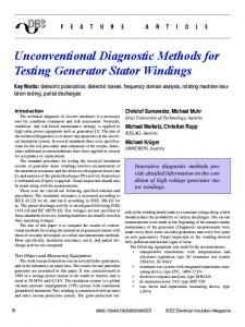
Algorithm 4 Guided flow based on the NLM filter ˜, I ˜0 , half W, h, λ) 1: function F LOW NLM(D, I � ˜ 2: R, Z ← 0, 0 . zero matrices at size I 3: for n ∈ [−half W, . . . , half W ]2 do � � ˜n − I ˜0 ∗ h 4: V ← exp −λ · squared I 5: R ← R + V Dn . : component-wise product 6: Z ← Z+V 7: end for 8: return R/Z 9: end function With the above function F LOW NLM, we upsample the input ˜i enforcing temporal coherence video Di with the guide video I of the upsampled frames. The algorithm removes time-varying noise and enhances the input depth. In the tests presented in the next section, we used the proposed video upsampling method Algorithm 5. The main loop contains a sequence of filtering steps. At each step, the flow is warped at the lower resolution, then the warped flow is combined with the subsequent input frame. Finally, the combined states are used as the input for upsampling. The upsampling results of the previous frames are propagated to the next frame to be processed using a method indicated as ‘combine’ in the algorithm below. In our tests, ‘combine’ was a simple pixel-wise running average filter. Algorithm 5 Algorithm for upsampling a sequence of depth images guided by a sequence of intensity images �� 1: Dprev ← resize D1 , 2 · size D1 � ˜1 , params 2: D1hi ← U PSAMPLE @ FILTER , D1 , I 3: for i ← 1 to (#f rames − 1) do � ˜i , I ˜i+1 , params 4: D ← F LOW NLM Dprev , I � 5: D0 ← resize Di+1 , size (Dprev ) 6: D00 ← combine (D, D0 ) � ˜00 ← resize I ˜i+1 , size (D0 ) 7: I � ˜00 , params 8: Dprev ← @ FILTER D00 , I � ˜i+1 , params 9: Di+1 hi ← U PSAMPLE @ FILTER , Dprev , I 10: end for IV. T ESTS We compared the two proposed algorithms for image-guided depth upsampling on both synthetic and real data. Sample results of the comparison are shown in Fig. 1. One can observe the significant difference between the two methods at depth edges which are more blurred in the case of Algorithm 3. On the other hand, the pixel grouping based Algorithm 2 better separates the objects in depth which is visually appealing. The input colour images used in the tests have features that make the task of the algorithms more difficult. The images contain steep transitions (edges) in texture and colour that cause troubles when the optical and the depth edges do not coincide. This may lead to the so-called texture copying (transfer) by Algorithm 3. (See [37], [32] for discussions of the texture transfer problem.) The Algorithm 2 produces less texture copying but it occasionally cuts into regions of
SMC_2016 002075
2016 IEEE International Conference on Systems, Man, and Cybernetics • SMC 2016 | October 9-12, 2016 • Budapest, Hungary
input colour image
resized depth
depths upsampled with Algorithms 2 (left) and 3 (right)
Fig. 1. Input and output images of our tests: the original colour images, the depth image resized to colour image size, and the upsampled depths with using the two proposed algorithms. The first three rows show synthetic data from the Middlebury stereo datasets [30]. The last row shows real data captured in a studio.
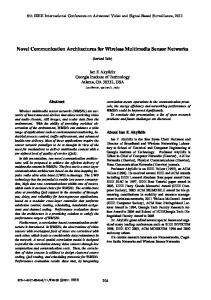
otherwise coherent depth pixels. These effects are visible in rows 2 and 3 of Fig. 1. Algorithm 2 is a purely local procedure that acts on local groups of pixels relying on the guidance image. The above mentioned depth cuts into homogeneous depth regions along the optical edges can happen because of the iterative manner of the algorithm. Pixel grouping repeated on varying scales by Algorithm 1 propagates the artefact. Fortunately, these cuts into coherent depth regions are not deep. Algorithm 3 which is a modification of NLM tries to emulate global image processing. It does not really concentrate on local features, thus the depth edges can become blurred. When these edges are also borders of indistinctive texture regions, the blurring effect may become stronger as demonstrated in row 2 of Fig. 1. Selection of the method to use depends on the application addressed. Sample results of the proposed video-guided upsampling Algorithm 5 are demonstrated in Fig. 2 where image sets
for two different frames can be seen1 . Each set contains four images as described in the caption. The resolution and the quality of the input depth are quite low. Time-varying noise and fluctuations lead to the disturbing fluctuations and blur in the single-frame upsampling. Warping the previously upsampled frame to the next state by the proposed Algorithm 4) and combining the result with the next input frame removes the time-varying fluctuations. V. C ONCLUSION We presented two novel algorithms for upsampling a depth image using a higher-resolution colour guidance image. We also proposed a novel method for upsampling depth videos based on Non-Local Means filtering. Initial tests demonstrate the applicability of the proposed algorithms to the standard synthetic as well as real studio data. Comparing the proposed algorithms, we observed that they have different features that 1 Data
courtesy of Zinemath Zrt [39].
SMC_2016 002076
2016 IEEE International Conference on Systems, Man, and Cybernetics • SMC 2016 | October 9-12, 2016 • Budapest, Hungary
first frame
second frame Fig. 2. Illustration of video-based depth upsampling. For each frame, the upper row shows the resized depth image and the corresponding optical image. The lower row shows upsampling results by the single-frame Algorithm 3 (left) and the video-guided Algorithm 5 (right).
can be advantageous in different applications. It was shown that using temporal coherence by the proposed video-guided method results in significant improvement compared to the single-frame approach. In near future, we plan to perform qualitative tests on the existing synthetic [25] and real [10] benchmarks comparing the proposed algorithm to state-of-theart approaches. ACKNOWLEDGMENT The authors are grateful to Zinemath Zrt for providing test data. This research has been supported in part by the ”Highly industrialised region on the west part of Hungary with limited R&D capacity: Research and development programs related to strengthening the strategic future oriented industries manufacturing technologies and products of regional competences carried out in comprehensive collaboration” program of the National Research, Development and Innovation Fund, Hungary, Grant. No. VKSZ 12-1-2013-0038. R EFERENCES [1] S.P. Awate and R.T. Whitaker. Higher-order image statistics for unsupervised, information-theoretic, adaptive, image filtering. In Proc. Conf. on Computer Vision and Pattern Recognition, volume 2, pages 44–51, 2005. [2] A. Buades, B. Coll, and J.-M. Morel. A non-local algorithm for image denoising. In Proc. Conf. on Computer Vision and Pattern Recognition, volume 2, pages 60–65, 2005.
[3] A. Buades, B. Coll, and J.-M. Morel. A review of image denoising algorithms, with a new one. Multiscale Modeling & Simulation, pages 490–530, 2005. [4] A. Buades, B. Coll, and J.-M. Morel. A review of image denoising algorithms, with a new one. Multiscale Modeling & Simulation, 4:490– 530, 2005. [5] D. Chetverikov, I. Eichhardt, and Z. Jank´o. A brief survey of imagebased depth upsampling. In Hungarian Conference on Image processing ´ and Recognition (KEPAF 2015), pages 17–30, 2015. [6] Laurent Condat. A simple trick to speed up and improve the non-local means. Technical Report hal-00512801, HAL, France, 2010. [7] P. Coup´e, P. Yger, S. Prima, P. Hellier, C. Kervrann, and C. Barillot. An optimized blockwise nonlocal means denoising filter for 3-D magnetic resonance images. IEEE Transactions on Medical Imaging, 27(4):425– 441, 2008. [8] Y. Cui, S. Schuon, D. Chan, et al. 3D shape scanning with a timeof-flight camera. In Proc. Conf. on Computer Vision and Pattern Recognition, pages 1173–1180, 2010. [9] A. Dauwe, B. Goossens, H.Q. Luong, and W. Philips. A fast non-local image denoising algorithm. In Electronic Imaging 2008, pages 681210– 681210. International Society for Optics and Photonics, 2008. [10] D. Ferstl, C. Reinbacher, R. Ranftl, M. R¨uther, and H. Bischof. Image guided depth upsampling using anisotropic total generalized variation. In Proc. Int. Conf. on Computer Vision, pages 993–1000, 2013. [11] S. Foix, G. Alenya, and C. Torras. Lock-in Time-of-Flight (ToF) Cameras: A Survey. Sensors Journal, 11(9):1917–1926, 2011. [12] S. Foix, R. Aleny`a, and C. Torras. Exploitation of time-of-flight (ToF) cameras. Technical Report IRI-DT-10-07, IRI-UPC, 2010. [13] P. Gemeiner, P. Jojic, and M. Vincze. Selecting good corners for structure and motion recovery using a time-of-flight camera. In Int. Conf. on Intelligent Robots and Systems, pages 5711–5716, 2009. [14] M. Grzegorzek, C. Theobalt, R. Koch, and A. Kolb (Eds). Time-of-Flight and Depth Imaging. Sensors, Algorithms, and Applications. Springer, 2013. [15] S.A. Guomundsson, R. Larsen, H. Aanæs, et al. ToF imaging in smart room environments towards improved people tracking. In Proc. Conf. on Computer Vision and Pattern Recognition Workshops, pages 1–6, 2008. [16] M. Hansard, S. Lee, O. Choi, and R. Horaud. Time-of-flight cameras. Springer, 2013. [17] B. Huhle, T. Schairer, P. Jenke, and W. Straßer. Fusion of range and color images for denoising and resolution enhancement with a non-local filter. Computer Vision and Image Understanding, 114:1336–1345, 2010. [18] S. Hussmann and T. Liepert. Robot vision system based on a 3DToF camera. In Proc. Conf. on Instrumentation and Measurement Technology, pages 1–5, 2007. [19] Y.M. Kim, C. Theobalt, J. Diebel, et al. Multi-view image and ToF sensor fusion for dense 3D reconstruction. In ICCV Workshops, pages 1542–1549, 2009. [20] A. Kolb, E. Barth, R. Koch, and R. Larsen. Time-of-flight cameras in computer graphics. In Computer Graphics Forum, volume 29, pages 141–159, 2010. [21] J. Kopf, M.F. Cohen, D. Lischinski, and M. Uyttendaele. Joint bilateral upsampling. In ACM Transactions on Graphics, volume 26, pages 673– 678, 2007. [22] M. Mahmoudi and G. Sapiro. Fast image and video denoising via nonlocal means of similar neighborhoods. IEEE Signal Processing Letters, 12:839–842, 2005. [23] S. May, D. Droeschel, D. Holz, et al. 3D pose estimation and mapping with time-of-flight cameras. In Proc. IROS Workshop on 3D Mapping, 2008. [24] R. Nair, K. Ruhl, F. Lenzen, et al. A Survey on Time-of-Flight Stereo Fusion. In Time-of-Flight and Depth Imaging. Sensors, Algorithms, and Applications, pages 105–127. Springer, 2013. [25] J. Park, H. Kim, Y.-W. Tai, et al. High quality depth map upsampling for 3D-ToF cameras. In Proc. Int. Conf. on Computer Vision, pages 1623–1630, 2011. [26] F. Remondino and D. Stoppa. ToF range-imaging cameras. Springer, 2013. [27] C. Richardt, C. Stoll, N. A Dodgson, et al. Coherent spatiotemporal filtering, upsampling and rendering of RGBZ videos. In Computer Graphics Forum, volume 31, pages 247–256, 2012. [28] Alan R Robertson. The cie 1976 color-difference formulae. Color Research & Application, 2(1):7–11, 1977.
SMC_2016 002077
2016 IEEE International Conference on Systems, Man, and Cybernetics • SMC 2016 | October 9-12, 2016 • Budapest, Hungary
[29] J.R. Ruiz-Sarmiento, C. Galindo, and J. Gonzalez. Improving human face detection through ToF cameras for ambient intelligence applications. In Ambient Intelligence-Software and Applications, pages 125– 132. Springer, 2011. [30] D. Scharstein, H. Hirschm¨uller, Y. Kitajima, G. Krathwohl, N. Nesic, X. Wang, and P. Westling. Middlebury stereo datasets. vision.middlebury.edu/stereo/data/, 2001–2014. [31] S. Schwarz, M. Sj¨ostr¨om, and R. Olsson. Temporal consistent depth map upscaling for 3DTV. In IS&T/SPIE Electronic Imaging, pages 901302–901302, 2014. [32] Y. Soh, J.Y. Sim, C.S. Kim, and S.U. Lee. Superpixel-based depth image super-resolution. In IS&T/SPIE Electronic Imaging, pages 82900D– 82900D. Int. Society for Optics and Photonics, 2012. [33] L. Szirmay-Kalos, B. T´oth, and T. Umenhoffer. Hierarchical volumetric fusion of depth images for slam. In Hungarian Conference on Computer Graphics and Geometry (GRAFGEO 2016), pages 43–47, 2016. [34] J.T. Thielemann, G.M. Breivik, and A. Berge. Pipeline landmark detection for autonomous robot navigation using time-of-flight imagery. In Proc. Conf. on Computer Vision and Pattern Recognition Workshops, pages 1–7, 2008. [35] R. Vignesh, B.T. Oh, and C-C J. Kuo. Fast non-local means (NLM) computation with probabilistic early termination. IEEE Signal Processing Letters, 17:277–280, 2010. [36] L.P.J. Vosters, C. Varekamp, and G. de Haan. Evaluation of efficient high quality depth upsampling methods for 3DTV. In IS&T/SPIE Electronic Imaging, pages 865005–865005, 2013. [37] Q. Yang, N. Ahuja, R. Yang, et al. Fusion of Median and Bilateral Filtering for Range Image Upsampling. IEEE Trans. Image Processing, 22:4841–4852, 2013. [38] F. Yuan, A. Swadzba, R. Philippsen, et al. Laser-based navigation enhanced with 3D time-of-flight data. In Proc. Int. Conf. on Robotics and Automation, pages 2844–2850, 2009. [39] Zinemath Zrt. The zLense platform. www.zinemath.com/, 2014.
SMC_2016 002078