Oct 5, 2011 - map γ â Lâ(Ω), suppose that there exists a constant c > 0 such that câ1 .... int · ν on âD. A representation of the solution using Green's .... Note that both P and Q are symmetric, negative definite provided |x â y| ... For non-explicit curves âD, the only non-routine step is the evaluation of the double integrals.
NUMERICAL COMPUTATION OF APPROXIMATE GENERALIZED POLARIZATION TENSORS
arXiv:1110.1022v1 [math.NA] 5 Oct 2011
YVES CAPDEBOSCQ, ANTON BONGIO KARRMAN, AND JEAN-CLAUDE NÉDÉLEC
Abstract. In this paper we describe a method to compute Generalized Polarization Tensors. These tensors are the coefficients appearing in the multipolar expansion of the steady state voltage perturbation caused by an inhomogeneity of constant conductivity. As an alternative to the integral equation approach, we propose an approximate semi-algebraic method which is easy to implement. This method has been integrated in a Myriapole, a matlab routine with a graphical interface which makes such computations available to non-numerical analysts.
1. Introduction The classical electrical impedance tomography problem in two dimensions can be described as follows. Suppose that Ω ⊂ R2 is a bounded simply connected domain. Given a conductivity map γ ∈ L∞ (Ω), suppose that there exists a constant c > 0 such that c−1 ≤ γ < c. Define the Dirichlet-to-Neumann map Λ : H 1/2 (∂Ω) → H −1/2 (∂Ω) by ∂u Λ(φ) := γ , ∂ν ∂Ω where u ∈ H 1 (Ω) is the voltage potential associated with γ, that is, the unique solution of div(γ∇u)
=
u =
0 in Ω φ on ∂Ω.
The electrical tomography problem is then to reconstruct γ from Λ. The fact that γ is uniquely determined by Λ has recently been established in dimension two [10], and this question is still open in dimension three. It is known however that, without additional assumptions on the conductivity, this problem is extremely ill-posed [1]. This ill-posedness can be considerably reduced in several cases of practical importance by the introduction of a priori information on the form of the conductivity to be recovered. One such problem is the following: given complete (or incomplete) knowledge of the Dirichlet-to-Neumann map, estimate the internal conductivity profile under the assumption that γ is constant except at a finite number of small inhomogeneities. This problem, and some variants, has been investigated by many authors (to name a few, see [4, 11, 12, 13, 16] and references therein). One important step in this estimation procedure is the derivation of an asymptotic expansion of the voltage potential u in terms of the volume of the inhomogeneities. For an isolated inhomogeneity, the inhomogeneity dependent parameters in the first order of this expansion are called the Polarization Tensor (a constant 2 × 2 matrix). The generalization of this tensor includes higher order terms dependent on the inhomogeneity via what is referred to as the Generalized Polarization Tensor (GPT) (see [3, 2, 5]) and was generalized to the case of linear elasticity (see [8]). These tensors appear in various contexts. In homogenization theory, they provide asymptotic expansions for dilute composites (see [17, 9]). Very recently, GPT’s have been used to reconstruct shape information from boundary measurements [7] and to construct approximate cloaking devices [6]. In these last two papers, the authors consider the following conductivity transmission problem: ( div ((1D γ1 + (1 − 1D ) γ0 ) ∇u) = 0 in R2 , −1 u(x) − H(x) = O(|x| ) as |x| → ∞, 1
2
YVES CAPDEBOSCQ, ANTON BONGIO KARRMAN, AND JEAN-CLAUDE NÉDÉLEC
where γ1 > 0 and γ0 > 0 are constants, 1D is the characteristic function of a bounded domain D ⊂ R2 with a Lipschitz boundary and a finite number of connected components, and H is a given harmonic function. In the absence of the inclusion D, u = H. Then, the far-field perturbation of the voltage potential created by D is given by u(x) − H(x) = −
(1.1)
∞ X |α|,|β|=1
(−1)|α| α ∂ Γ(x)Mαβ ∂ β H (x0 ) as |x| → ∞, |α|! |β|!
where x0 is the center of mass of D, and Γ is the fundamental solution of the Laplacian, 1 Γ(x) := − ln |x| . 2π The parameters α = (α1 , α2 ) and β = (β1 , β2 ) are multi-indices, and |α| = α1 + α2 . The real valued tensors Mαβ , which depend on D and on the conductivity contrast γ1 /γ0 are the so-called GPT. In bounded domains, expansions similar to (1.1) are also available, where Γ is replaced by a suitable Green’s Function (see [4]). To fix ideas, let us assume x0 is the origin. As it is observed in [6], the expansion (1.1) can be simplified when expressed in terms of harmonic polynomials which are real or imaginary parts of (x1 + ix2 )n where x = (x1 , x2 ). Introducing n
n
an (x) := rn cos(nθ) = < ((x1 + ix2 ) ) ,
bn (x) := rn sin(nθ) = = ((x1 + ix2 ) ) ,
if H can be written in the form H(x) = H(0) +
∞ X
αn (H)an (x) + βn (H)bn (x),
n=1
then it is shown in [6] that the expansion (1.1) can be written under the form u(x) − H(x)
= +
∞ am (x) X (M (am, an ) αn (H) + M (am, bn ) βn (H)) 2πm|x|2m n=1 m=1 ∞ X
∞ X
∞ bm (x) X (M (bm, an ) αn (H) + M (bm, bn ) βn (H)) , as |x| → ∞. 2πm|x|2m n=1 m=1
The authors of [6] refer to M (P, Q), where P and Q are any of the harmonic polynomials an or bn , as the contracted GPT. Such an expansion is particularly relevant if the inclusion is observed on a sphere SR (of radius R) centered at the origin. In such a case, it is well known that an and bn form a basis of L2 (SR ) - this is the Fourier series decomposition. The tensor coefficients M (P, Q) are given by the formula Z (1.2) M (P, Q) = P (x)φQ (x) dσ(x), ∂D
where φ
(1.3)
Q
solves the transmission problem ∆φQ φQ + ∂φQ γ1 ∂φQ − ∂ν + γ0 ∂ν − φQ
= = =
0 in D and R2 \ D, φQ on ∂D, −
∂Q on ∂D, ∂ν
→ 0 as |x| → ∞,
where ν is the normal pointing outside of D, and where the subscript + (resp. −) refers to the limit taken along the normal from the outside (resp. the inside) of D. The subject of this paper is to detail a simple algorithm to compute approximate values of the contracted GPT M (P, Q). We focus on the case when γ1 is constant, and D is a simply connected inclusion with a C 1 boundary. In Section 2, we show that this problem can be written in a weak form as a system of boundary integral equations on ∂D2 := ∂D × ∂D. Such an approach is wellknown amongt numerical analysts interested in integral equations. We use an integration by parts formula that can be found in [14, 18]. In Section 3, in the spirit of mixed finite-elements methods,
NUMERICAL COMPUTATION OF APPROXIMATE GENERALIZED POLARIZATION TENSORS
3
we decouple the boundary voltage potential from the normal flux and approximate them in the following way: φQ − ∈ span (a1 , b1 , . . . , aN1 , bN1 ) , � � ∂φQ ∂ ∂ ∂ ∂ ∈ span a1 , b1 , . . . , aN , bN , ∂ν − ∂ν ∂ν ∂ν 2 ∂ν 2 for a given a fixed N1 and N2 , greater than or equal to the order of Q. We verify that the corresponding linear system is invertible. There are two advantages of this approach. The first is that since an and bn are explicit polynomials, their gradient can also be computed explicitly. The precision with which the normal is calculated depends on the parameterization of D, which is independent of N1 and N2 . The second is that the problem then involves the computation of 4(N1 + N2 )2 integrals on ∂D2 , and then the inversion of a 4(N1 + N2 )2 matrix. In other words, this decouples the order of the contracted GPT from the discretization of the boundary D. In Section 4, we discuss the results obtained for disks and ellipses, for which the exact values of the contracted GPT are known. Finally, in Section 5 , we present a Matlab routine (named Myriapole on the Matlab Central exchange repository) that implements this approach. 2. Weak boundary integral formulation of the transmission problem In this section, we derive the following variational formulation satisfied by the transmission problem. Proposition 2.1. Let φQ be the solution of the transmission problem (1.3). Introducing the notations γ1 ∂φQ ∈ H −1/2 (∂D), k = , uQ := φQ ∂D ∈ H 1/2 (∂D), v Q := ∂ν − γ0 the pair (uQ , v Q ) satisfies for any φ ∈ H 1/2 (∂D), Z Z ∂uQ ∂φ ∂Γ(x − y) (k + 1) (y) (x)Γ(x − y) dσ(x)dσ(y) + 2k v Q (y)φ(x) dσ(x)dσ(y) ∂τ ∂τ ∂νx 2 2 ∂D Z Z ∂D ∂Q ∂Q ∂Γ(x − y) 1 (x)φ(x) dσ(x) − (y)φ(x) dσ(x)dσ(y), = 2 ∂D ∂ν ∂ν ∂νx 2 ∂D and for all ψ ∈ H 1/2 (∂D), Z Z ∂Γ(x − y) Q (k + 1) v (y)ψ(x)Γ(x − y) dσ(x)dσ(y) − 2 uQ (y)ψ(x) dσ(x)dσ(y) ∂νy 2 2 ∂D Z∂D ∂Q (2.1) (y)ψ(x)Γ(x − y) dσ(x)dσ(y). =− 2 ∂D ∂ν Proof. In order to solve the transmission problem of (1.3), we separate the interior potential from the exterior by defining the following: (2.2)
uQ (x) := φQ (x) for x ∈ D, and φQ ext (x) := φQ (x) for x ∈ R2 \ D.
We then introduce the gradient fields as (2.3)
vQ int (x) := ∇uQ (x), and vQ ext (x) := ∇φQ ext (x),
and set v Q = vQ int · ν on ∂D. A representation of the solution using Green’s identities leads to the expression of the interior solution and its gradient in terms of first and double layer potentials. For all x ∈ D, we have Z ∂Γ(x − y) uQ (x) = uQ (y) − v Q (y)Γ(x − y) dσ(y), ∂ν y ∂D � � Z ∂Γ(x − y) Q Q v int (x) = u (y)∇x − v Q (y)∇x Γ(x − y) dσ(y), ∂ν y ∂D
4
YVES CAPDEBOSCQ, ANTON BONGIO KARRMAN, AND JEAN-CLAUDE NÉDÉLEC
As x → ∂D from the interior, using the jump conditions satisfied by single and double layer potentials [15], we obtain for x ∈ ∂D, Z 1 Q ∂Γ(x − y) u (x) = − v Q (y)Γ(x − y) dσ(y), (2.4) uQ (y) 2 ∂ν y ∂D Z 2 1 Q ∂Γ(x − y) ∂ Γ(x − y) (2.5) v (x) = − v Q (y) dσ(y). uQ (y) 2 ∂ν ∂ν ∂νx x y ∂D Similarly, for all x ∈ R2 \ D we have Z � ∂Γ(x − y) φQ ext (x) = − φQ ext (y) − vQ ext (y) · ν Γ(x − y) dσ(y), ∂νy ∂D � � Z � ∂Γ(x − y) φQ ext (y)∇x vQ ext (x) = − − vQ ext (y) · ν ∇x Γ(x − y) dσ(y). ∂νy ∂D And passing to the limit as x → ∂B for the exterior, we obtain Z � 1 Q ∂Γ(x − y) φ ext (x) = − φQ ext (y) (2.6) − vQ ext (y) · ν Γ(x − y) dσ(y), 2 ∂νy ∂D Z 2 � ∂Γ(x − y) ∂ Γ(x − y) 1 Q (2.7) v ext (x) · ν = − φQ ext (y) − vQ ext (y) · ν dσ(y), 2 ∂νx ∂νy ∂νx ∂D We subtract (2.6) from (2.4) and use (1.3) and (2.2) to obtain for x ∈ ∂D, Z Z ∂Γ(x − y) Q 2 u (y) (2.8) dσ(y) − (1 + k) v Q (y)Γ(x − y) dσ(y) ∂ν y ∂D Z ∂D ∂Q (y)Γ(x − y) dσ(y). = ∂D ∂ν Similarly, from (2.5) and (2.7) we have, for x ∈ ∂D, Z Z ∂Γ(x − y) ∂ 2 Γ(x − y) Q 2k v (y) (2.9) dσ(y) − (1 + k) uQ (y) dσ(y) ∂νx ∂νx ∂νy ∂D ∂D Z ∂Q ∂Γ(x − y) 1 ∂Q (x) − (y) dσ(y). = 2 ∂ν ∂ν ∂νx ∂D We test (2.8) against φ ∈ H 1/2 (∂D) and obtain Z Z ∂Γ(x − y) ∂uQ ∂φ 2k v Q (y)φ(x) dσ(x)dσ(y) + (1 + k) (y) (x)Γ(x − y) dσ(x)dσ(y) ∂νx ∂τ ∂D 2 ∂D 2 ∂τ Z Z 1 ∂Q ∂Q ∂Γ(x − y) = (x)φ(x) dσ(x) − (y)φ(x) dσ(x)dσ(y). 2 ∂D ∂ν ∂νx ∂D 2 ∂ν We have used the following integration by parts formula proved in [14, 18], Z Z ∂ 2 Γ(x − y) ∂uQ ∂φ − uQ (y)φ(x) dσ(x)dσ(y) = (y) (x)Γ(x − y) dσ(x)dσ(y). ∂ν ∂ν ∂τ ∂τ 2 2 x y ∂D ∂D Finally, we test (2.9) against ψ ∈ H 1/2 (∂D) to obtain Z Z ∂Γ(x − y) Q 2 u (y)ψ(x) dσ(x)dσ(y) − (1 + k) v Q (y)ψ(x)Γ(x − y) dσ(x)dσ(y) ∂νy ∂D 2 ∂D 2 Z ∂Q = (y)ψ(x)Γ(x − y) dσ(x)dσ(y). 2 ∂D ∂ν which concludes the proof.
�
To conclude this section, we provide two equivalent formulations for the tensor M (P, Q) in terms of the unknowns uQ and v Q .
NUMERICAL COMPUTATION OF APPROXIMATE GENERALIZED POLARIZATION TENSORS
5
Proposition 2.2. The contracted GPT defined in (1.2) is also given by � � Z ∂Q M (P, Q) = (k − 1) (x) + (k − 1)v Q (x) dσ(x), P (x) ∂ν ∂D and
Z M (P, Q) = (k − 1) ∂D
� ∂P (x) Q + (k − 1)uQ (x) dσ(x). ∂ν
Proof. The first formula is proved in [4, Lemma 3.3]. The latter is obtained after an integration by parts of the former. � 3. Approximate resolution method To solve the system given in (2.1), we restrict it to a finite-dimensional space. More precisely, given N1 and N2 two positive integers, we set np := 2N1 and nq := 2N2 and define ( when i ≤ np is odd, a i+1 2 Pi := when i ≤ np is even, b 2i and ( ∇a i+1 · ν
Qi :=
when i ≤ nq is odd,
2
∇b 2i ·
when i ≤ nq is even,
and we consider (2.1) as a system posed on � � H = span P1 , . . . , Pnp × Q1 , . . . , Qnq . We write uQ =
2N1 X
cn Pn , and v Q =
n=1
2N2 X
dn Qn ,
n=1
and thus (2.1) becomes a linear system of the form MX = B, where X is a (np + nq ) × nq matrix, where for q ≤ k ≤ N2 , the k-th column contains the coefficients the of (uak , v ak ) and the N2 + k-th column the coefficients of (ubk , v ak ). For 1 ≤ i, j ≤ np , Z ∂Pj ∂Pi (y) (x)Γ(x − y) dσ(x)dσ(y). Mi,j = (k + 1)Pi,j , with Pi,j = ∂τ ∂τ 2 ∂D For 1 ≤ i ≤ np and np + 1 ≤ j ≤ np + nq Z Mi,j = 2kNi,j , with Ni,j =
Qj−np (y)Pi (x) ∂D 2
∂Γ(x − y) dσ(x)dσ(y). ∂νx
For np + 1 ≤ i ≤ np + nq , and 1 ≤ j ≤ np , Z ∂Γ(x − y) Mi,j = −2 Qj−np (x)Pj (y) dσ(x)dσ(y) = −2Nj,i . ∂νx 2 ∂D For np + 1 ≤ i, j ≤ np + nq , Z Mi,j = (k + 1)Qi,j , with Qi.j =
Qj−np (x)Qi−np (y)Γ(x − y) dσ(x)dσ(y). ∂D 2
The right-hand-side term B is a (np + nq ) × nq matrix, given when 1 ≤ i ≤ np by Z Z 1 ∂Γ(x − y) Bi,j = Qj (x)Pi (x) dσ(x) − Qj (y)Pi (x) dσ(x)dσ(y), 2 ∂D ∂νx ∂D 2 and when np + 1 ≤ i ≤ np + nq , Z Bi,j = −
Qj (y)Qj−np (x)Γ(x − y) dσ(x)dσ(y). ∂D 2
Note that both P and Q are symmetric, negative definite provided |x − y| < κ < 1, that is, provided the perimeter of D is smaller than 2κ. This assumption is not restrictive: we can scale
6
YVES CAPDEBOSCQ, ANTON BONGIO KARRMAN, AND JEAN-CLAUDE NÉDÉLEC
D to be sufficiently small for the computations. In that case, since we established that the matrix M is of the form (k + 1) P 2kN , M= T −2N (k + 1) Q it has as a positive determinant and therefore this linear-system is well-posed. For any i and j such that max(i, j) ≤ min(np , nq ), the contracted GPT coefficients are then computed using Proposition 2.2, namely ! Z nq X M (Pi , Pj ) = (k − 1) Pi (x) Qj (x) + (k − 1) Xm,np +j Qm (x) dσ(x), ∂D
m=1
or equivalently by Z M (Pi , Pj ) = (k − 1)
Qi (x) Pj (x) + (k − 1) ∂D
nq X
! Xm,j Pm (x) dσ(x).
m=1
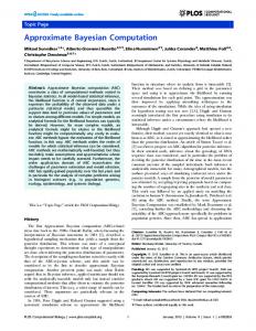
For a fixed pair (i, j), increasing the number np and nq improves the accuracy of the method, to a point. Note that P , Q and Γ are explicitly given in terms of x and ν(x). To compute the integrals which appear in M, B and finally for M , we mostly need to choose a parameterization of ∂D, and to compute its normal. If ∂D is given by an analytic formula, these integrals can all be computed using symbolic computation software. In this sense, the method is partially algebraic. For non-explicit curves ∂D, the only non-routine step is the evaluation of the double integrals involving Γ(x − y) and ∇Γ(x − y) · ν(x) on the line-segments (or on the arcs) where x − y cancels (or is smaller than a threshold). However, approximations for these integrals can be computed "by hand," thanks to the explicit form of the integrands. 4. Numerical results for disks and ellipses In order to test our method, we consider geometries for which exact formulae for the contracted GPT are known, that is, disks and ellipses. If the inclusion is a disk, the contracted GPT is diagonal, and given by � �i |D| 2iπ . (4.1) M (P2i−1 , P2j−1 ) = M (P2i , P2j ) = δij k+1 π The formula for ellipses is slightly more involved, but also explicit (see [5, Prop. 4.7]). In this case, an algebraic approach (as described above) would provide exact results. Thus we use these shapes as a first benchmark for more complex geometries, for which the analytic formulae do not exist or are unknown. We compute the integrals appearing in Section 3 using a midpoint rule and fixing N1 = N2 . In a first experiment, for a perfect disk of radius .5, we study the influence of the resolution of the boundary discretization and the number of polynomials used in the basis to compute the contracted GPT up to order 4. Figure 4.1 shows a plot of the result. The value represented is the maximal relative absolute difference between the approximate tensor and the exact tensor. For a tensor M 0 approximating M , the relative error is given by � = max
(4.2)
i,j
0 M − Mij ij . max |Mkl |
k,l≥min(i,j)
As i and/or j increases,
max k,l≥min(i,j)
|Mkl | decreases: this scaling factor compensates the variation
of tensor’s coefficient size. Figure 4.1 shows that the error behaves as we could expect. If the number N of harmonic polymonial used is less than twice the order (in these results, n = 4), the results are incorrect. Note that the harmonic polynomials come in pairs as real and imaginary parts of (x1 +ix2 )m , thus it makes sense to expect accurate results for tensors of order n only if the maximal degree (m in this case) of the representation of u is greater than n (m > n). Once this threshold is passed, the error decreases with the number of discretization points independently of the number of polynomials used.
NUMERICAL COMPUTATION OF APPROXIMATE GENERALIZED POLARIZATION TENSORS Log
10
7
Maximum Relative Error
Order = 4, Contrast = 1/3, R = .5 −0.5
500
450
Number of Boundary Points
−1 400
350 −1.5 300
250 −2 200
150
−2.5
100 −3
50 5
10
15
20
25
30
Number of Polynomials Representing u(x)
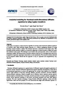
Figure 4.1. Relative error for GPT up to order 4. With the same geometry and the same order, we use 9 harmonic polynomials, and test the behavior of this method as the contrast increases, for various discretizations. The result is shown in Figure 4.2. Higher contrast k > 1 leads to greater errors, but the error remains bounded when the contrast tends to zero. With the same geometry, and a contrast of 1/3, we now fix the number Log10 Maximum Relative Error vs. Log10 Contrast Order = 4, Polynomial Count = 9, R = .5 2
Log10 Maximum Relative Error
0
−2
−4
−6
−8 16 Points 64 Points 256 Points 1024 Points 10% Rel. Err. 1% Rel. Err.
−10
−12 −2
−1.5
−1
−0.5
0
0.5
1
1.5
2
2.5
3
Log10 Contrast Ratio
Figure 4.2. Error vs. conductivity ratio. The error is bounded for k ≤ 1 and increases with k > 1. For a point-count of 1024 and k ≈ 10, the relative error is less than 1%. of polynomials used as a function of the order (2n + 1 polynomials, where n is the tensor order) and increase the order. The result is shown in Figure 4.3. The image on the right represents the same data as that on the left but with a different scale on the vertical axis to show more detail. When too few points are used to discretize the boundary, that is, 16 or 32 points, the left plot shows that the ill-conditioning of the linear system causes extremely divergent results. For the other cases, the results are consistent. For tensors up to order 28, a parameterization point-count of 256 points gives relative errors of less than 1 percent for this disk case. Moving away from a perfect disk, we now investigate how the algorithm fares with ellipses of high eccentricity. Again, fourth order tensors were calculated and the same error measures were used. The ellipse with semiaxis lengths of a = .005 and b = .5 gives vastly different results
8
YVES CAPDEBOSCQ, ANTON BONGIO KARRMAN, AND JEAN-CLAUDE NÉDÉLEC Log10 Maximum Relative Error vs. Tensor Order
Log
10
14 16 Points 32 Points 64 Points 128 Points 256 Points 512 Points 10% Rel. Err. 1% Rel. Err.
10
−1.5
Log10 Maximum Relative Error
Log10 Maximum Relative Error
12
Maximum Relative Error vs. Tensor Order
8
6
4
2
0
−2
−2.5
−3
16 Points 32 Points 64 Points 128 Points 256 Points 512 Points 1% Rel. Err.
−3.5
−2
−4
0
5
10
15
20
25
30
−4
0
5
Tensor Order
10
15
20
25
30
Tensor Order
Figure 4.3. Results for higher order tensors for a disk of radius one and conductivity ratio equal to 1/3. compared to the results from the disk. The first difference to note is that with 32 points, the approximation is not even close to the exact tensor. The first plot in Figure 4.4 shows the expected general trend that for larger polynomial-count and boundary point-count, error is smaller. However, there is an interesting phenomenon for the case of high point-count; as the number of polynomials representing u and v increases, error attains a minimal value but then after a certain point begins to increase. This is most likely due to floating point errors in Matlab that round the high-degree polynomials off and then add this error across each boundary segment at points on the more pointed edges of the ellipse. The second plot in Figure 4.4 gives another clear example of the inaccuracies of the ellipse for 32 boundary points, the increased error for k > 0, and the existence of an "optimal" polynomialcount for parameterizations of high point-count. Also, the difference between k < 1 and k > 1 is clear in this case, as can be seen in the second plot. Lastly, we considered the amount of time taken to calculate tensors for the unit disk. On a 64-bit, 2.3 GHz machine, Matlab computed fourth order tensors according to the results given in Table 1. Table 1. Calculation Time (seconds): Timing results for a tensor of order 1 and 10 each using two different polynomial-counts: one equal to the minimal required amount, and one equal to twice the minimal required amount. Tensor Order 1 10
Number of Polynomials 16 Points 3 .0149 6 .0188 21 .0308 42 .3055
256 Points .0340 .0467 .1063 .4712
1024 Points .8890 1.1463 2.7794 5.4148
5. A Matlab package with graphical user interface To extend the algorithm, we have developed a Matlab graphical user interface that calculates contracted GPT’s of any shape. The interface provides an efficient and user-friendly implementation of the algorithm described above and allows the user to easily change parameters used in the calculation. In this context, it also serves as a useful tool for further investigation into the accuracy of the computation for disks and ellipses. It is available from the Matlab Central File Exchange server under the name ’Myriapole’.
NUMERICAL COMPUTATION OF APPROXIMATE GENERALIZED POLARIZATION TENSORS Log
10
9
Maximum Relative Error for an Eccentric Ellipse Order = 4, Contrast = 1/3, a = .005, b = .5
500 −0.2 450
Number of Boundary Points
−0.4 400 −0.6 350 −0.8
300
250
−1
200
−1.2
150 −1.4 100 −1.6 50 5
10
15
20
25
30
Number of Polynomials Representing u(x) Log10 Maximum Relative Error for an Eccentric Ellipse Order = 4, a = .005, b = .5 0.5
Log10 Maximum Relative Error
0
−0.5
32 Points, Contrast = 1/3 32 Points, Contrast = 3 512 Points, Contrast = 1/3 512 Points, Contrast = 3 10% Rel. Err.
−1
−1.5
−2
0
5
10
15
20
25
30
35
Number of Polynomials Representing u(x)
Figure 4.4. Results for ellipse of considerable eccentricity with semiaxes a = .01 and b = 1. The general region where the relative error is below 10 percent is where polynomial-count is greater than 10 and point-count is greater than 200.
Figure 5.1. The layout of the graphical user interface Myriapole. The principal parameters of contracted GPT’s are its order and conductivity contrast. Order in this situation refers to the highest power of x1 + ix2 appearing in the set of polynomials P used for the calculation of M (Pi , Pj ). Therefore, a contracted tensor of order n will be a matrix of size 2n × 2n, where each odd row and column correspond to Pm =