BBAA VI International Colloquium on: Bluff Bodies Aerodynamics & Applications Milano, Italy, July, 20-24 2008
NUMERICAL INVESTIGATION OF THE FLOW AROUND A RECTANGULAR CYLINDER NEAR A SOLID WALL Stefano Malavasi∗, Nicola Trabucchi† ∗
Dipartimento di Ingegneria Idraulica, Ambientale, Infrastrutture Viarie, Rilevamento Politecnico di Milano, piazza Leonardo da Vinci 32, 20133 Milano, Italy. e-mail:
[email protected]
†
Dipartimento di Ingegneria Idraulica, Ambientale, Infrastrutture Viarie, Rilevamento Politecnico di Milano, piazza Leonardo da Vinci 32, 20133 Milano, Italy. e-mail:
[email protected]
Keywords: CFD, rectangular cylinder, force coefficients, mean flow structure, asymmetrical bounded flow.
ABSTRACT In this work numerical simulations of the flow around a cylinder of rectangular cross section placed at different elevation above a solid wall are performed. This configuration could be used to study many engineering problems (e.g. pipelines near the sea bottom, river structures, etc.). The numerical analysis of the flow around bluff bodies has gained popularity in the last decades due to the rapid advance of the computer technology and accuracy of CFD prediction. In literature there are many examples of this kind of studies, notwithstanding the rectangular shape has been mainly considered for unbounded or symmetrically bounded flow ([5] [6]). Recent studies on asymmetrical confined flow are performed at the Politecnico di Milano. Malavasi and Guadagnini [1] dealt with the interaction between a free-surface flow and a rectangular cylinder, which is investigated by means of mean hydrodynamic coefficients and vortex shedding frequencies, besides Blois and Malavasi [3] investigated the flow field structures involved in the same experimental configuration with a PIV technique. Moreover, Cigada et al. [2] studied the effect that the presence of a wall induces on the fluid dynamic loading affecting a rectangular cylinder placed in a wind tunnel at several elevations from the wall itself. These experimental results highlight the significant difference between the unbounded or symmetrical bounded condition, typical of aerodynamic studies of bluff bodies ([4]), and the asymmetrical bounded flow condition.
1
The aim of this work is to perform opportune numerical simulations of the experimental cases considered to improve the available information about this phenomenon. The commercial CFD code Flow3D® has been used to perform the simulations: the program solves the governing equations of flow in the form of common unsteady Reynolds-average Navier-Stokes (URANS) and the Reynolds stresses, added by the averaging process, are modeled with a RNG k-ε turbulence model. This is known to be an efficient model and it is wide used for the simulation of flow around bluff bodies [7]. In our work numerical simulations of water flow are performed reproducing the experimental setup used by Malavasi and Guadagnini [1]. The numerical model is used to investigate especially the case of small distances from the bottom (corresponding to hb/s < 3) where the complexity of the phenomenon needs additional information that the numerical simulation provides. In literature numerical and experimental analysis of the bounding effects of the presence of a wall are present, but only for circular and square cylinder [8] [9]. In order to obtain an increasing reliability of the simulation results, a validation procedure of numerical model has been held in sense of meshing and boundary dependency. At first the aerodynamics of the rectangular body in unbounded condition, which was investigated in detail both experimentally and numerically, is discussed to validate the applicability of our approach using RANS model and verifying the present numerical code. Good agreement with the literature [5] is found in terms of mean drag, oscillating lift and mean pressure coefficient distribution around the bluff body. The numerical parameters used for the validation helped the set-up of the bounded-wall condition simulation. The negligible effect of the free-surface that has been experimental verified for the small elevation cases allows performing confined numerical simulation, disregarding the numerical treatment of the free-surface. 6.0
4.0
experimental
experimental
3.5
numerical
4.0
numerical + blockage ef f ect
3.0 CD 2.5
2.0
CL
0.0
2.0
-2.0
1.5
-4.0
1.0
-6.0
0.5
-8.0
0.0
0.0
0.5
1.0
1.5 h /s 2.0 b
2.5
3.0
0.0
0.5
1.0
1.5 h /s 2.0 b
2.5
3.0
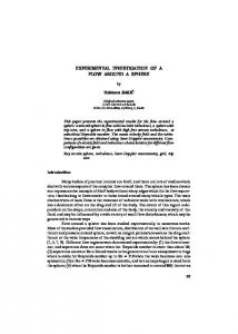
Figure 1 : Mean force coefficients for different hb/s ratio ([1]) and comparison with numerical simulated value (test case: Re = 12000; L/s = 3; for hb/s =1, γb = 0.167)
The reliability of the simulations has been verified comparing the simulated mean hydrodynamic coefficients with the experimental ones, plotted versus the hb/s ratio where hb is the distance of the low side of the cylinder from the bottom wall and s is the thickness of the cylinder. The comparison between the experimental and numerical data is more consistent if considering the correction of the drag coefficient due to the experimental blockage effect, absent in present numerical simulations. In Figure (1) the correction of numerical drag coefficient is performed using the equation proposed by Simiu and Scanlan [10]: Cd cor = Cd num × (1 + K × γ b )
2
(1)
where Cdnum is the coefficient numerically simulated, K is a coefficient equal to 1.6 for the considered aspect ratio L/s and γb is the experimental blockage coefficient. Moreover mean flow field is derived averaging the numerical velocity field over four oscillating cycles of the lift coefficient. Using the flow feature extraction procedure used in the post-processing of PIV mean flow field [3] the numerical simulated mean flow field is analyzed. Main geometrical dimension of vortex structure around the cylinder, vortex core, stagnation and reattachment point are evaluated (Figure 2).
Figure 2 Mean velocity field around the obstacle, simulated case: L/s = 3; hb/s = 1, Re = 12000. Streamlines and characteristic points of the mean flow structure are shown (■ reattachment points; ○ stagnation point; ▲ saddle ; z vortex centers ).
The mean numerical simulated velocity field for different elevation of the cylinder above the bottom wall is compared with the cinematic ones from PIV investigation (Table 1).
hb/s = 1 PIV Numerical Reattachment point location xu/s
2.25
2.20
Reattachment point location xd/s
0.74
0.83
0.44
0.48
Stagnation point location
y/s
Table 1 Comparison between experimental and numerical mean flow structure reconstruction, test case: L/s = 3; hb/s = 1, Re = 12000. (xu and xd are the distance between the leading edge and the reattachment point respectively at the cylinder extrados and intrados, while y is the distance between the distance between the intrados leading edge and the position of the stagnation point).
The results of dynamic and kinematic comparison between experimental and numerical simulation allow us to use the numerical approach to populate data not experimental available on the phenomenon, e.g. the mean pressure distribution both on the cylinder and the bottom wall. The possibility to extract this kind of information provides a significant help in the understanding of the experimental evidence and in the phenomenon interpretation.
3
REFERENCES [1] S. Malavasi, A. Guadagnini. Interactions between a rectangular cylinder and a free-surface flow. Journal of Fluids and Structure, 23, 1137–1148, 2007. [2] A. Cigada et. al. Effects of an asymmetrical confined flow on a rectangular cylinder. Journal of Fluids and Structure, 22, 213–227, 2007. [3] G. Blois, S. Malavasi. Flow structure around a rectangular cylinder near a solid surface. XVIII AIMETA Conference, Brescia, Italy, September 11-14, 2007. [4] A. Okajima. Flow around a rectangular cylinder with a section of various depth/breath ratios. Journal of Wind Engineering, 17, 79-80, 1983 [5] K. Shimada, T. Ishihara. Application of a modified k-epsilon model to the prediction of aerodynamic characteristics of rectangular cross-section cylinders. Journal of Fluids and Structure, 16, 465–485, 2002. [6] D. Yu, A. Kareem. Parametric study of flow around rectangular prisms using LES. Journal of Wind Engineering and Industrial Aerodynamics, 77, 653–662, 1998. [7] B.A. Younis, V.P. Przulj. Computation of turbulent vortex shedding. Computational Mechanics, 37, 408-425, 2006. [8] G. Bosh, W. Rodi. Simulation of vortex shedding past a square cylinder near a wall. Int. Journal of Heat and Fluid Flow, 17, 267-275, 1996. [9] R.J. Martinuzzi et.al. Influence of wall proximity on vortex shedding from a square cylinder. Experiments in Fluids, 34, 585-596, 2003. [10] E. Simiu, R.H. Scanlan. Wind effects on structures. John Wyley & Sons, 1996.
4