fluids are introduced into monolith channels, the manifolds cause severe pressure losses. Therefore, in this work, turbulent flow regime at low Reynolds numbers.
Advanced Computational Methods in Heat Transfer X
25
Numerical simulation of fluid flow in a monolithic exchanger related to high temperature and high pressure operating conditions F. Selimovic & B. Sundén Division of Heat Transfer Faculty of Engineering, LTH Box 118, 221 00 Lund, Sweden
Abstract The purpose of this work is the enhancement of performance by a new design of monolithic heat exchangers under steady-state operating conditions. Heat transfer phenomena and hydrodynamics have been studied and visualized by computational fluid dynamics (CFD). Further, a simple gas distribution system has been analyzed in purpose to find the best performance of the exchanger. To achieve this, 3D simulations of air flow were performed. One of characteristics of monolithic structures is the low pressure drop and high heat transfer coefficient. This is because they operate in the laminar flow regime and have high compactness. However, some experimental studies show that when two fluids are introduced into monolith channels, the manifolds cause severe pressure losses. Therefore, in this work, turbulent flow regime at low Reynolds numbers has been investigated to find the difference and better understanding of these structures, which are of interest in high temperature applications today. The simulation shows that the pressure drop of the gas flow distributor is a key parameter affecting the heat transfer in the exchanger channels. Keywords: high temperature heat exchangers, gas flow maldistribution, monolithic heat exchangers, computational fluid dynamics.
1
Introduction
Monolith structures are used in industry today and they are produced by extrusion techniques. They are uni-body structures composed of interconnected WIT Transactions on Engineering Sciences, Vol 61, © 2008 WIT Press www.witpress.com, ISSN 1743-3533 (on-line) doi:10.2495/HT080031
26 Advanced Computational Methods in Heat Transfer X repeated cells or channels. Mainly these structures are used in single-fluid applications and are made of metallic materials, e.g., the monolithic exhaust structure in automotive applications, heat sinks, etc. If the two fluids can exchange heat and/or mass there would be greater reaction rates and exchangers with small dimensions would be advantageous. This is the case if these structures contain micro- or mini-channels because the heat and mass transfer coefficients exceed the values of conventional devices. Their vacuum tightness, the high pressure stability of several hundreds bar, and the flame-arresting properties of the fine micro channels, even allow for reactions with high educt concentrations in the explosion range, [1]. Especially two-fluid monoliths made of ceramics with micro-channels would open up new fields of application, e.g., high-temperature reactions. However, only few attempts have been made to manufacture monolithic components from ceramics, e.g., by lamination of ceramic green tapes, [2]. Usually high pressure losses through manifolds have also been a drawback so that the design geometry needs to be adjusted to limit pressure losses to acceptable levels. In other words usage of monolithic structures in two-fluid applications would be possible, if carefully designed distribution headers are assembled and could guarantee against excessive flow maldistribution and avoid unacceptable pressure drops. In a previous work, [3], one manifold design solution was presented. It has been found both experimentally and computationally that the largest pressure drop occurs in manifolds and distributor plates for a two-fluid exchanger. In this work an idea for a monolithic ceramic heat and/or mass reactor/exchanger will be presented. Starting from the geometrical design, results obtained by computational fluid dynamics (CFD) simulation for the pressure losses, flow maldistribution, heat transfer will be given. The aim of the present study is to present a computational investigation of a monolithic structure using CFD predictions over a wide range of operating conditions used in high temperature application such as catalyst reactors. Heat transfer phenomena and hydrodynamics are studied and visualized by CFD.
2
Two fluid exchanger model
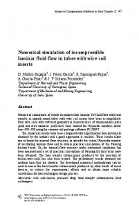
An idea for a new design of the two-fluid exchanger is illustrated in Figure1. In this study five-channels with ten manifold inlet and outlet stacks for each fluid are considered. From Figure 2b) five-channels repeating unit can be observed. Main inlets and outlets with flow distribution into channels are illustrated in Figure 2a). The exchanger is to be operated in counterflow mode, where heat and mass exchange can take place by linear channel arrangement. The cooling fluid, Fluid 2, enters the exchanger at the bottom manifold at right where cold fluid, Fluid 1 does it at the top, Figure 1. This solution for the flow manifolds differs from previous work [3] because when linear channel arrangement is introduced, one can avoid having complex header system in contrast to system having a checkerboard channel arrangement. Computer model of the exchanger is limited by computational expenses. For that purpose the computational model of the monolith exchanger has been scaled WIT Transactions on Engineering Sciences, Vol 61, © 2008 WIT Press www.witpress.com, ISSN 1743-3533 (on-line)
Advanced Computational Methods in Heat Transfer X
27
Figure 1:
Principle setup of a counterflow mini-channel monolithic heat exchanger.
Figure 2:
(a) Guided mass flows from inlet manifold into exchanger channels. (b) Computational domain for one repeated unit.
WIT Transactions on Engineering Sciences, Vol 61, © 2008 WIT Press www.witpress.com, ISSN 1743-3533 (on-line)
28 Advanced Computational Methods in Heat Transfer X down to centimetre level. The model of the exchanger will be represented only by one "repeating unit" which is illustrated in Figure 3. A repeated unit with inlet and outlet manifolds is 200 mm long and has a cross-section of 10 mm x 10 mm with 5 channels with height of 100 mm. The channels have the same crosssection as the manifolds. The present model contains 5 monolithic channels but in real systems more channels are possible and should be considered from design point of view. However, heat transfer and pressure drop will be analyzed for this model caused by maldistribution and the following correction equation will cover cases for the 5 channels considered.
3
CFD modelling
The commercially available CFD code FLUENT is used to predict steady state heat transfer performance of the monolithic structure. Figure 3 represents a grid example chosen for the simulations. The working fluid for the cases studied is air. Results are collected for pressure drop, fluid flow maldistribution and heat transfer. Because of earlier experience in experimental analysis of monolith heat exchanger [3], low Reynolds variant of k- model has been used in simulation to find correction for pressure loss. Therefore, special care is taken to the location of the computational nodes near the wall. Turbulence intensity has been set to 5%. 3.1 Modelling equations and boundary conditions The equations that govern fluid motion and heat transfer are: the continuity, momentum and energy equations. In modelling of turbulence the standard kmodel with additionally two-layer low Reynolds number model have been used. For further details about the modelling equations, see [4]. A velocity inlet boundary condition (uniform velocity distribution with a direction vector normal to the inlet boundary) was applied at the fluid inlet flow manifold. At the outlet, the boundary condition was assigned as outlet which means that gradients of all flow properties except pressure are set to zero. If the direction normal to the outlet boundary is denoted by y, the outlet boundary condition is expressed as in [1]. represents all the scalar variables of interest (temperatures, physical properties etc). The walls are treated as adiabatic besides two channel-walls which are main contributors to the heat transfer in this structure. Pressure drops over the inlet manifold and outlet manifold are calculated by area weighted averages. When the pressures drop across them are known the inlet and outlet boundaries are changed to pressure inlet and pressure outlet which allows using the ideal gas model for density of air [4].
0
(1)
The simulations are run for the following cases of Reynolds number occurring in the channels: 30, 150, 500 and 900. Heat transfer of a rectangular channel has been analyzed for the temperature boundary condition of the third kind: the local wall heat flux is a linear function WIT Transactions on Engineering Sciences, Vol 61, © 2008 WIT Press www.witpress.com, ISSN 1743-3533 (on-line)
Advanced Computational Methods in Heat Transfer X
29
of the local wall temperature, [5], where both left and right walls of monolithic exchanger channels have been heated at constant wall temperature of 1100K. To obtain a dimensionless representation of the pressure drop due to the manifold and channels, the friction factor f based on adiabatic conditions was introduced according to the Fanning definition: (2) The variable local and average Nusselt numbers for the channel left or right wall are based on the convective heat transfer coefficient hx and it is defined as: (3) (4) Where Tbulk is the bulk stream-wise flow temperature in the cross section of the duct. | | | |
(5)
The dimensionless axial distance y* in the flow direction for the hydrodynamic entrance region is defined as (6) Friction factor has been compared with the cases for fully developed laminar flow and for the case of monolithic exchanger with checkerboard channel arrangement, found in [3]. For laminar case, Fanning friction factor is correlated to [6]: 14.227 (7) and for the case of checkerboard arrangement : . r 110.5 (8) 3.2 Computational grid and solution procedure A structured grid is used for the simulations in the computational domain. At the end of iterations, the maximum changes in the value of each dependent variable are calculated. The criterion of the maximum changes is set to 1E-4. To achieve grid independence several sensitivity grid-tests were carried out. Test cases were performed for grids with 135000, 200000, 300000, and 600000 computational elements. Standard k- model does not give acceptable grid independence even if the amount of computational cell is increased up to 600000, Figure 6. Therefore, the standard k- model turns out to be inadequate to capture all the small-scale feature of turbulence (without using unsteady state equations). A necessity of applying another turbulence model is obvious. An enhanced wall treatment is used in order to find better convergence. Enhanced wall treatment is a near-wall modelling method that combines a twolayer model with enhanced wall functions. As can be observed in Figure 6 (left), the total pressure profile calculated with enhanced wall treatment model with WIT Transactions on Engineering Sciences, Vol 61, © 2008 WIT Press www.witpress.com, ISSN 1743-3533 (on-line)
30 Advanced Computational Methods in Heat Transfer X 135000 cells matches the result achieved by the standard k- model with 600 000 cells. Figure 6 (right), shows influence of different grid sizes using enhanced wall treatment model. Convergence has been achieved with 200 000 computational elements. Therefore, this grid size is used for the rest of simulations. Numerical solution has been performed by means of the commercial software FLUENT 6.3.26 where each of differential equations has been transformed into the general transport equation form: (9)
Figure 3:
The computational domain and detailed view of grid used in calculations. Finer mesh is used near walls.
Figure 4:
Iterations procedure for each steady-state simulation. (Observe residual jump when QUICK method is turned on in pressure drop simulations).
WIT Transactions on Engineering Sciences, Vol 61, © 2008 WIT Press www.witpress.com, ISSN 1743-3533 (on-line)
Advanced Computational Methods in Heat Transfer X
Figure 5:
31
Influence of grid size of predicted results (Pressure profile at the entrance to third channel), standard k-ε model used in calculations.
4 Results and discussion In order to assess the quality of the results, simulations were carried out using two higher order schemes: a second-order upwind method and the QUICK method. The resulting system of non-linear algebraic equations was underrelaxed and solved by the SIMPLE algorithm. The iteration procedures started with investigation of pressure drop (i.e., test without heating) until the convergence criteria were reached. Thereafter the energy equation was turned on and the analysis was further continued until convergence, Figure 4. The parameters such as the heat transfer coefficient, temperature at the outlet, mass flow rate, turbulence y+ values were monitored during the simulations to better control the convergence of solutions. Each analysis consumed totally 4 hours (2000 iterations) on Intel Core 2 Duo 2.4 GHz computer with 2 GB RAM memory with memory speed of 667MHz dual channel. Due to the lack of published experimental data in the literature, for simultaneously developing flow in rectangular ducts only fully developed friction factor and Nusselt number are used for comparison with the model. The friction factor behaviour for the investigated cases of channel Reynolds number can be seen in Figure 7. The friction characteristic of the linear channels monolith seems to have a magnitude between the characteristics of the laminar [6], and checkerboard [3] cases. As expected, the friction factor is lower than for the laminar case with some turbulence intensity existing at the inlet boundary. The fact that the present design avoids a complex distributor plate causes the pressure losses to be lower than those for the case of the checkerboard monolith.
WIT Transactions on Engineering Sciences, Vol 61, © 2008 WIT Press www.witpress.com, ISSN 1743-3533 (on-line)
32 Advanced Computational Methods in Heat Transfer X
Figure 6:
Influence of the grid size on the predicted results (Pressure profile at the entrance to third channel), enhanced wall treatment model used in all calculations.
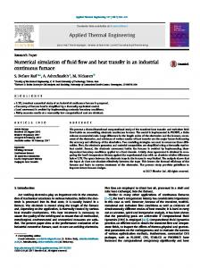
Figure 7:
Left: Flow friction characteristics. Right: Nusselt number along the main flow direction, Re=160 (data taken from inlet to outlet of the first channel).
The correlation between the friction factor and Reynolds number has been found to: . (10) 218.4 WIT Transactions on Engineering Sciences, Vol 61, © 2008 WIT Press www.witpress.com, ISSN 1743-3533 (on-line)
Advanced Computational Methods in Heat Transfer X
33
It is valid for: 30 1000. Hydrodynamic and thermal boundary layer development caused by forced convection makes Nusselt number to decay in the downstream increasing y*, Figure 8. High values of Nusselt number at the channel entrance are caused by the driving potential for heat transfer of cold fluid at the entrance into the channels. At some position y* along the channel Nu approaches its fully developed value which is calculated to 4.7. As expected this value is higher than the laminar case because of flow regime is in the transition zone. The following formula is an empirical fit of data obtained from numerical simulations: log
1.366
21.86
121.78
1506.8
11224.7
(11)
Typical longitudinal decrease of Nu number with increasing y* can be found, (see Figure 9). The thermal boundary layer development is disrupted by the two side walls which are not contributing to the heat transfer and also by the nonuniform fluid velocity (see Figure 11). At the entrance of the each channel a vortex motion increases the heat transfer and fluid temperature as can be observed from Figure 12. This effect diminishes with increasing y*. The same effect explains the curve trends in Figure 10 and Figure 11. 1
Re=160
35
2
30
3
25
4
Nu
20
5
15 10 5 0 0
Figure 8:
0.5
x/Dh
1
Spanwise distribution of Nusselt number Nu into Channel 1 (curve 1, y*=0.0619; curve 2, y*=0.040; curve 3, y*= 0.032; curve 4, y*=0.014; curve 5, y*=0.005.
5 Conclusions Numerical simulations of developing flow in the transition region and heat transfer in a five monolithic square channel were presented for various Reynolds numbers. The current 3D CFD simulation was applied on vertical channels arranged by linear flow arrangement where constant wall temperature was
WIT Transactions on Engineering Sciences, Vol 61, © 2008 WIT Press www.witpress.com, ISSN 1743-3533 (on-line)
34 Advanced Computational Methods in Heat Transfer X 33
40
Re=160
Re=160
30
Nu
Nu
23
20
13
10 3 0 ‐7 0
0.5 x/Dh
1
0
0.5
x/Dh
1
Figure 9:
Left: Spanwise distribution of Nusselt number Nu in Channel 3 (curve 1, y*=0.0619; curve 2, y*=0.040; curve 3, y*= 0.032; curve 4, y*=0.014; curve 5, y*=0.005). Right: Spanwise distribution of Nusselt number Nu in Channel 5 (curve 1, y*=0.0619; curve 2, y*=0.040; curve 3, y*= 0.032; curve 4, y*=0.014; curve 5, y*=0.005).
Figure 10:
Axial temperature contour plot at different y* locations in all 5 channels.
applied on two walls and thermal insulation on the other two walls. From the structure of gas flow and temperature field it was found that the generated vortex at the entrance of each channel caused disruption of both the hydrodynamic and thermal boundary layer. Further, the total pressure drop was found to be somewhat higher than the values from the literature for laminar flow but lower for a monolithic exchanger where the channels have been arranged in a checkerboard flow arrangement. Also a correlation for the heat transfer coefficient was established and the values are higher than for the strict laminar flow. This was explained by the transition flow regime operation of the
WIT Transactions on Engineering Sciences, Vol 61, © 2008 WIT Press www.witpress.com, ISSN 1743-3533 (on-line)
Advanced Computational Methods in Heat Transfer X
Figure 11:
35
v-veloocity contour plot located at a the middle of z-plane (O Observe negatiive prefix for downward d velocity).
exchannger. Finally, this study might m be regaarded as an improved moodelling proceddure for gas flow and convective c heat h transfer in monolithic heat exchanngers/reactors..
Referrences [1] W Wunsch, R., M. M Fichtner, O. O Görke, Kaatja-Haas-Santto, and K. Scchubert. Prrocess of Appplying Al2O3 Coating in i Microchannnels of Coompletly Ma Manifactured M Microstructure ed Reactors., Chem. C Eng.Teech. 25, s. 7, 22002. [2] Scchmitt C., et al Ceramic Plate P Heat Exxchanger for Heterogeneoous Gas Phhase Reactionss, Chem Eng. Technol., 28 8 (3), s. 337, 2005. 2 [3] Seelimovic, F., Sunden, B. and a Bruun, T. Computatioonal Analysis of Gas Fllow and Heatt Transport Phenomenain in i Monolithicc Structures foor High Teemperature Prrocesses. San Francisco: AS SME Proceeddings HT2005-72183, 20005. [4] Fluuent 6.3 User''s guide. 20066. [5] Javveri, V., Lam minar Heat Transfer T In a Rectangular Channel F For The Teemparature Booundary Conddition Of The Third Kind., Int. I J. Heat annd Mass Trransfer, 21, ss.. 1029–1034, 1977. [6] Shhah, R.K. andd London, A. L. Laminar Flow F Forced Convection C inn Ducts. u.oo. : Academicc Press, ISBN 0-12-020051--1, 1978. [7] Incropera, F P and a DeWitt, D P. Fundameentals of Heatt and Mass Tr Transfer. Neew York : Willey, 1996.
WIT Transactions on Engineering Sciences, Vol 61, © 2008 WIT Press www.witpress.com, ISSN 1743-3533 (on-line)