Numerical Simulation of the Hemming Process in the case of Al Alloys S. Thuillier, N. Le Maoût, P.Y. Manach LG2M, Université de Bretagne Sud Rue de Saint-Maudé, BP 92116, F-56321 Lorient Cedex
[email protected] Abstract. This work deals with the 2D numerical simulation of a hemming process. It consists of tree steps: bending, pre-hemming and final hemming; springback occurs in-between each forming operations. This study investigates the influence of the constitutive law on force-displacement curves as well as on the geometry of the hemmed. Three hardening laws are considered, i.e isotropic, kinematic and mixed hardening, and two yield criteria, i.e. Von Mises and Hill'48.
INTRODUCTION This paper deals with the numerical simulation of the hemming process. This forming process is usually considered in three steps [1]: a bending or flanging step followed by a pre-hemming step and then the final hemming step. It is frequently used in automotive industry as a joining process between the inner reinforcing skin and the outer skin as well as to avoid sharp and cutting edges for security sake. Hemmed parts are doors and deck-lids. Hemming is the final process after drawing operations and occurs on an already plastically deformed material by multiple-step operations. Moreover, springback takes place inbetween each operations. Hemming is performed over metallic parts with a complex geometry and generally speaking, parts are non-planar and are bent along a curved line [2,3], inducing either compressive and tensile stress states. In order to have a better understanding of the influence of the process parameters, hemming is usually considered as an isolated process starting from the flanging step; virgin samples are then bent or flanged, pre-hemmed and finally hemmed. The influence of parameters such as the die radius in the flanging operation, the flange length, the pre-hemming punch travel has been investigated on the final product quality [4].
Numerical simulations of hemming process have also been performed [5,6,7,8]; as in the case of deepdrawing process, these simulations require a large transformation framework, elasto-plastic constitutive laws, contact and friction between rigid tools and the blank. Contact between two deformable bodies has also to be considered, in-between inner and outer skins. The deformation is highly localized, up to an equivalent plastic strain of the order of 0.3 after bending and up to 1.0 at the end of the process, over an area of length 1 mm. Concerning the material mechanical behavior, isotropic hardening has solely been considered in previous studies [1,6,8]. However, it is now well established that the taking into account of the Bauschinger effect, via kinematic hardening, has a strong influence over the prediction of springback, e.g. [9,10,11,12]. It seems therefore interesting to investigate the influence of the material constitutive behavior on the numerical prediction of a hemming process. Therefore, this studies deals with the influence of the constitutive behavior on the numerical simulation of a 2D hemming process. Calculations are perfomred using the finite element code Abaqus®. In this work, Von Mises and Hill'48 yield criteria are considered and isotropic, kinematic and mixed hardening laws describe the plastic behavior.
HEMMING PROCESS This study deals with a numerical investigation of the influence of the constitutive behavior on the simulation of a hemming process. Process parameters described below were chosen as representative of actual values found in the literature and used in industrial process. Planar and rectangular sheets are considered and a two-dimension finite element model is then developed.
work, the distance between the binder and the die is kept constant. A punch orientated at 45° to the die is moved down and will bend further the blank, down to 45° approximately. The punch is then moved up and springback occurs. The final forming step starts with the going down of the horizontal hemming punch. It folds the blank over the inner skin, down to a final thickness of the assembly of 3 times the blank thickness. The hemming punch is then moved up.
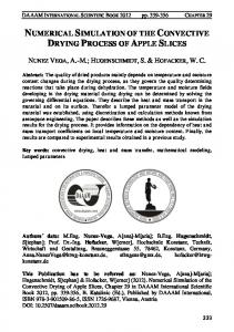
Geometry Of The Process The bending step is a drawing operation (Fig.1). The blank is held between a die and a binder and a punch bends a small height of the sheet over the die. The die radius is an important parameter, which usually varies between 0.5 mm and to 2.0 mm, depending on the material. A lower radius will induce a higher localized equivalent plastic strain in the bent area and then a decreased springback effect after removal of the tools [13]. The gap between the die and the punch is larger than the blank thickness t, it is set equal to 1.1 times the blank thickness, e.g. [5]. The flange length is fixed to 8 mm in this work, typical values are found in-between 4 mm and 12 mm [1]. The distance between the binder and the die is kept constant in order to generate an equivalent stress in this area lower than the initial yield stress. The binder presses the sheet against the die; the punch is moved up and then moved down.
FIGURE 1. Schematic drawing of the bending process. The gap between the punch and the die is equal to 1.1 t.
The bent sheet, also called outer skin, is then set over a hemming die (Fig.2) and the inner skin is slightly pressed on the outer blank by a binder. The inner skin thickness is equal to the blank thickness. In an industrial process, the binding force depends on the available space and is sometimes not present. In this
FIGURE 2. Schematic drawing of the pre-hemming and hemming steps. In a first step, the binder is moved down to press slightly the inner skin on the outer one and on the die.
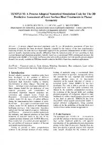
Numerical Simulation Of The Process 2D numerical simulation is performed with the finite element code Abaqus®. The length over which the blank is bent is usually very high, compared with the flange length (ratio of around 50) and therefore plane strain elements are considered. Strain is highly localized in the bent area and a non-uniform mesh is used (Fig.3). The outer blank is meshed using quadrangular elements with quadratic interpolation. 8 layers of elements are set through the thickness, within the bent area, with a non-uniform size of the elements along the thickness direction. Indeed, the element size decreases near the upper surface of the outer blank. The number of elements in the thickness is gradually decreased away from the bent area, there is 4 layers in area 1 and 2 layers in area 2, located at the other side of the plate. The inner skin in meshed also with 8-node elements and there are 3 layers of elements through the thickness. The mesh is slightly refined in the area where the outer skin comes into contact during the final step. A Coulomb friction coefficient is taken equal to 0.12 for all contact pairs, except the contact between the upper surface of the outer blank and both
the pre-hemming and hemming punch. It is then increased up to 0.17. Boundary conditions are such that nodes at extreme left-hand side of the plate (Fig.1) are clamped, both for the inner and outer skins
Two hardening variables are introduced: an isotropic hardening R associated to the equivalent plastic strain p and a non linear kinematic hardening X according to the Armstrong and Frederik model [14]. The evolution of R with the plastic strain is chosen with a saturation form of Voce type (2):
(
(
R = Q 1 − exp − b ε P
))
(2)
Inner skin Area 1
X=
C (σ − X )ε& P − γ X ε& P σ0
(3)
ε P and ε& P are the equivalent plastic strain and strain
Area 2 Outer skin
rate respectively. The material parameters to be identified are then: Young modulus E, Poisson ratio ν and σ 0 , Q , b, C and γ.
Bent area
FIGURE 3. 2D mesh of the inner and outer skins. Plane strain elements with quadratic interpolation are used.
Elastic and plastic deformations occur during the forming process. At room temperature, the viscosity effects are generally neglected and elasto-plastic constitutive laws are written within a large transformation framework. The constitutive laws considered in this study are those introduced in the standard version of the finite element code.
Elasto-plastic Constitutive Behavior The elastic part of the deformation is described by the isotropic Hooke law. The plastic part ε follows a
The material is an aluminum alloy. Material parameters are identified from tension and bendingunbending tests in the work of Brunet et al. [15], in the rolling direction. E = 69 GPa, ν = 0.33. 400 Mixed hard. Isotropic hard. Kinematic hard. 200 Cauchy stress (MPa)
CONSTITUTIVE BEHAVIOUR
Material parameters
0 -0.2
-0.1
0
0.1
0.2
-200
p
flow rule and is derived from the yield function f. The model is based on either Von Mises or Hill's 1948 yield criterion and f is then given by equation (1) 3 d d (1) f = (σ − X ) : H : (σ − X ) − σ 0 − R 2 where σ 0 is the initial yield stress in the rolling direction (RD).
σ is the deviatoric part of the stress d
tensor σ and H is the fourth order Hill’s tensor which considers the orthotropic symmetry of the material. It contains the six coefficients F,G,H,L,M and N defined by Hill.
-400 plastic strain
FIGURE 4. Numerical tension-compression tests, with the three hardening laws (isotropic, kinematic and mixed hardening).
Homogeneous tension-compression tests were simulated with Abaqus®, in order to estimate the amplitude of the Bauschinger effect (Fig. 4). Material parameters are given in Tables 1, 2 and 3. To take into account the normal anisotropy of the sheet, an average anisotropy coefficient of 0.73 is taken [15]. The Hill's coefficients are then calculated.
Four simulations were carried out, with the following constitutive laws: Von Mises isotropic yield criterion with either isotropic or kinematic or mixed hardening and finally Hill's 48 anisotropic criterion with isotropic hardening.
well as numerical results presented in [6], the load increases up to a maximum of around 32 N/mm for a punch stroke of 3.5 mm and then decreases. The nonzero force at the end of the stroke is due to friction forces. 25
TABLE 1. Material parameters for isotropic hardening. Q (MPa) b σ0 (MPa) 137.0 235.0 10.0
Isoptropic hard. Kinematic hard. Mixed hard. Anisotropic yield
load (N/mm)
20
TABLE 2. Material parameters for kinematic hardening. C (MPa) σ0 (MPa) γ 137.0 2300.0 9.8 TABLE 3. Material parameters for mixed hardening. Q (MPa) b σ0 (MPa) 137.0 111.6 13.56 C (MPa) γ 740.4 4.17
15
10
5
0 0
RESULTS AND DISCUSSION
4 displacement (mm)
6
8
FIGURE 6. Load vs displacement curve for the prehemming step.
Fig.5 features the load on the punch during the bending step. Whatever the hardening law, in the case of isotropic yield criterion, the load-displacement curves are very similar. Therefore, out of clarity reasons, only results obtained with a mixed hardening model are plotted.
70 Isotropic hard. Kinematic hard. Mixed hard. Anisotropic yield
60 50 load (N/mm)
Mixed hard. Anisotropic yield
30
2
40 30
load (N/mm)
20 20
10 0 0
10
2
4 displacement (mm)
6
FIGURE 7. Load vs displacement curve for the hemming step. 0 0
3 6 displacement (mm)
9
FIGURE 5. Load vs displacement curve for the bending step.
In the following, the load is expressed per unit length of hemmed sheet, in N/mm. As expected from experimental results previously published, e.g. [1] as
Fig.6 shows the load on the punch during the prehemming step. The overall shape of the curve is similar to previous studies [1]. Firstly, the load reaches a maximum around 16 N/mm. This maximum corresponds to a vertical position of the deformed blank. The load then decreases until a large part of the upper surface of the blank comes in contact with the pre-hemming punch. During this time, the blank rolls
around the inner skin, which is bent. Then, the blank is pressed down and the load increases significantly. TABLE 4. Several geometric factors of the blank after the forming steps. Angle variation Isotropic hard. Mixed hard. Kinematic hard. Bending (A1) 3.69° 3.63° 7.71° Pre-hemming (A2) 4.50° 4.49° 8.71° Hemming (A3) 0.77° 0.87° -4.47° Roll in/roll-out (mm) -1.80 -1.69 -1.83
Anisotropic yield 3.45° 4.23° 0.71° -1.76
When comparing results on Fig.6, it can be noticed that there are slight differences; however, the difference between the first maximum of the load calculated with isotropic hardening and the one calculated with a mixed hardening is less than 3%. Fig.7 shows the load on the punch during the hemming step. The load, after a first maximum of the order of 20 N/mm, decreases slowly during the bending of the blank. There is only a very small contact surface in-between the hemming punch and the upper surface of the blank. When the contact surface increases, the blank in then pressed down on the inner skin and the load sharply increases.
A1
FIGURE 8. Deformed mesh after bending and springback occur. Mixed hardening model.
For each step, the variation of the position of the blank before springback and after springback is calculated and presented in Table 4. After bending, and before the removal of the punch, the flanged part is almost vertical and there is a slight opening of around 3.6° (Fig.8), except for the kinematic hardening model, where the opening is at least two times higher. This high opening can be related to the highest maximum of the load on Fig.6 for such a material model. Indeed, as discussed above, this maximum occurs when the blank comes back to the vertical position. The shape variation at the end of pre-hemming (Fig. 9) is of the order of 4.5°, except for kinematic hardening model. At the end of hemming, shape variation is very low (Table 4 and Fig. 10). Generally speaking, it is observed that there is not a strong influence of the constitutive model on the predicted geometry. However, it should depend on the ratio of kinematic hardening to isotropic hardening. Roll-in is calculated as the difference between the total length of the hemmed part at the end of the process and the length obtained after flanging. This last measure is arbitrarily taken at a given height. This parameter, of great practical importance, is dependent on the constitutive law and a difference of 6% is found between isotropic hardening model and mixed hardening model.
A2
FIGURE 9. Deformed mesh after pre-hemming and springback occur. Mixed hardening model.
A3
FIGURE 10. Deformed mesh after hemming and removal of the punch. Mixed hardening model.
ACKNOWLEDGMENTS The authors are indebted to D. Debois and J. Leroy of PCI-Rennes for fruitful discussions on the hemming process. The authors would like to thank Pr. P. Pilvin, from LG2M, for his help on constitutive behavior modeling and material parameter identification.
REFERENCES 1. Muderrisoglu, A., Murata, M., Ahmetoglu, M. A., Kinzel, G. and Altan, T., J. Materials Processing Technology 59, 10-17 (1996). 2. Zhang, G., Hao H., Wu, X. and Hu, S. J., J. Manufacturing processes 2-4, 241-246 (2000). 3. Livatyali, H., Laxhuber, T. and Altan, T., J. Materials Processing Technology 146, 20-27 (2004). 4. Livatyali, H. and Larris, S. J., J. Materials Processing Technology 153-154, 913-919 (2004). 5. Zhang, G., Wu, X. and Hu, S. J., Journal of Engineering materials and Technology 123, 436-441 (2001). 6. Livatyali, H., Wu, H. C. and Altan, T., J. Materials Processing Technology 120, 348-354 (2002). 7. Svensson, M. and Mattiason K., Proceedings of Numisheet 2002, Jeju Island, October 21-25 (2002). 8. Livatyali, H., Muderrisolgu, A., Ahmetoglu, M. A., Akgerman, N., Kinzel, G. and Altan, T., J. Materials Processing Technology 98, 41-52 (2000). 9. Geng, L. and Wagoner, R.H., K., International Journal of Mechanical Sciences 44, 123-148 (2002). 10. Li, K.P., Carden, W.P. and Wagoner, R.H., International Journal of Mechanical Sciences44, 103-122 (2005). 11. Xia, Z.C., “A parametric study of springback behavior,” in Simulation of Materials Processing, edited by Mori, 2001, pp. 711-715. 12. Makinouchi, A., “Recent developments in sheet metal forming simulation,” in Simulation of Materials Processing, edited by Mori, 2001, pp. 3-10. 13. Livatyali, H. and Altan, T., J. Materials Processing Technology 117, 262-268 (2001). 14. Armstrong, P. J. and Frederick, C. O., CEGB report RD/B/N/, 731- (1966). 15. Brunet, M., Morestin F. and Godereaux, S., J. Engng. Materials Technology 123, 378-383 (2001).