CSMA 2017 13ème Colloque National en Calcul des Structures 15-19 mai 2017, Presqu’île de Giens (Var)
Microscopic modelling of weld formation in EMW: Open questions K. Macocco1, C. Scheffler 2, A. Deldicque3 1
PHIMECA, Paris, France,
[email protected] FRAUNHOFER, Chemnitz, Germany,
[email protected] 3 ICAM, Lille, France,
[email protected] 2
Abstract — In the frame of the JOIN’EM project, a microscopic model of the welding process in EMW is built mixing SPH and FEM method. This model is validated reproducing example from literature but it depends on various parameters. Some open questions have to be analyzed in order to build a coupling industrial tool. Key words — Welding, SPH, Johnson-Cook, Gruneisen.
1
Context and Objectives
The JOIN’EM project is funded by the EU in order to substitute components completely made of copper by welded hybrid copper-aluminum parts. This is for economic and environmental costs. The welding process is performed with an electro-magnetic field: the first component called “flyer” impacts the second component called “target” which is fixed. A macroscopic modelling is performed using a coupled electromagnetic-mechanical model based on a FEM and BEM approach. Due to the fast transient aspect of the phenomena, this process is modeled using the explicit code LS-Dyna. Complementing this macroscopic process modelling, a more detailed microscopic simulation of the joint development is developed for a deeper insight in the mechanism of the joint formation, thus allowing conclusions regarding cause-effect relationships as well as material-process interactions. The macroscopic modelling provides the impact angle and the impact velocity which are reused as input parameters in the microscopic model. But the SPH model depends also on other parameters which are difficult to estimate. The aim of this work is to evaluate the impact of these parameters and try to correlate them with measurements done at FRAUNHOFER.
2
Microscopic modelling of the process
2.1 Description First, a bibliography study is realized to identify if there is an indicators features which could indicate if the welding occurs or not. It seems there is no fixed consensus between researchers on the weldability indicators. The physics behind impact welding are not yet fully understood. But the two phenomena observed relatively frequently are:
The jet of material which is created by the energy released during the collision. It is composed by the materials of the flyer and the target proportionally to their densities. This jet cleans the surface and allows the welding by putting into contact the flyer and the target.
The morphology of the interface between the flyer and the target which could be straight or wavy or vortical.
In order to predict those, two numerical methods seem to be good candidate:
Pure Eulerian, SPH (Smooth Particle Hydrodynamics). 1
In order to predict the jet and the interface morphology which could be considered as weldability indicators, due to the high deformation and high speed deformation, we choose to use a mixed method SPH+FEM with LS-Dyna Software. This software is adapted to explicit dynamic calculation which is the case in the EMW process. The SPH method is able to model the produced jet during the EM process and FEM gives more accurate results and avoids heavy calculation which is the of the SPH method. The sheets length is assumed to be infinite (perpendicular to the plane). Therefore, 2D plane has been developed.
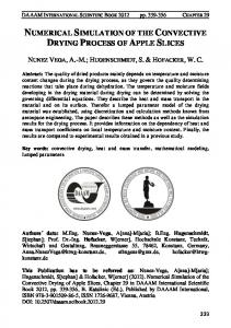
Flyer
Target
Figure 1: Geometry and initial conditions of the microscopic model
As an initial condition, an impact velocity is applied to the flyer. The target is fixed along the bottom edge. The mesh sizes (FEM and particle sizes) of the flyer and the target are the same. Concerning the material constitutive laws and using information coming from the bibliography, the reduced hardening law of Johnson-Cook is used: (1) where ε is the plastic strain rate, ἐ the strain rate (s-1), ἐ0 the reference plastic strain rate (s-1), A the yield strength coefficient (MPa), B the Hardening modulus coefficient (MPa), C the strain rate sensitivity coefficient, n the hardening coefficient. The effect of the temperature is not taken into account because we suppose that the process occurs in an isothermal state. A further analysis will be realized by ICAM in the next months, taking into account heat transfer, to verify the impact of this assumption on the simulations. Due to the shock and the encountered level of pressure, an equation of state (EOS) is required. The EOS is a mathematical description of the material behavior for a given set of initial conditions. Gruneisen equation of state can be used for solid and it is defined by (2) (3) (4) where V is the volume, p is the pressure, p0 pressure at reference state, is the internal energy, e0 internal energy at a reference state, Γ is the Grüneisen parameter, Γ0 Grüneisen parameter at reference state,
is the bulk speed of sound, ρ is the current density, ρ0 is the initial density, s is a linear
2
Hugoniot slope coefficient , E is the internal energy per unit reference volume
.
In the developed model, we consider the temperature is constant and equal to room temperature. Gruneisen EOS is recommended for high speeds.
2.2 Validation In order to validate the developed model, we compare performed results to some available results in the literature (cf. [1] and [2]) in terms of field shapes and to physical values. In this article, we compare some results from Nassiri & al. [1] simulations using ALE modelling. The geometry is described in Figure 2.
12mm
1mm 1mm
1mm
7° 0.6mm
2.4mm 15mm
Figure 2: Geometry of the simulated case in [1]
Concerning the SPH part, for the flyer and the target, the size of the particles is constant and equal to 0.025mm. The number of particles in the flyer is 19721 with a mass equal to 1.643.10-12t and in the target is equal to 15624 with a mass equal to 1.555.10-12t. The constant applied to the smoothing length of all particles is 1.2. Concerning the FEM part, for the flyer and the target, the mesh is regular and the size of the elements is equal to 0.05mm. The number of elements in flyer is 4800 and in the target is equal to 14400. The initial impact angle is equal to 7° and the initial normal impact velocity is equal to 350m/s. Using the material parameters (cf. Table 1 and Table 2) defined in [1] for flyer and target, we produce a microscopic model. Table 1 - Parameters used for Johnson-Cook law Material Aluminum
Table 2: Parameters used for Gruneisen EOS Material
(mm/s)
Aluminum
3
As we can see in Figure 3, the interface between the copper and the Aluminum is wavy and there are some SPH elements modelling the jet.
Figure 3 - LS-Dyna simulation of impact welding for a case presented in [1] at 2.4989.10-6 s
The jet is produced from the flyer and the target as it can be seen in Figure 4.
Figure 4: Wavy interface and jet at 2.4989.10-6 s
If we compare the velocity distribution in x direction in Figure 5 obtained in [1] and the computed velocity distribution in x direction in Figure 6. The shape of the distribution is very similar and the value at the collision point is very similar.
x
Figure 5: Velocity distribution in x-direction (from[1])
4
Figure 6: Velocity distribution in x direction near the collision point at 2.4989.10-6 s
In Figure 6, the velocity distribution in x direction looks almost symmetric because of the fact that we have the same material for the flyer and for the target: the material close to the collision of both sides moves with the same velocity and the maximum is observed at the collision point as shown in [1]. In order to validate the coupling between the macroscopic and the microscopic modelling, we compare the whole model to some experiments realized in the frame of another workpackage of Join’EM.
2.2 Application to Join’EM project In the frame of another task of this project, macroscopic simulations are performed with LS-Dyna. This classical FEA model takes into account the mechanical and electromagnetic interaction between the coil, the flyer and the target.
Coil
windin g
Flyer
Point
indicato rTarget
Support
Spacer
Figure 7: Cross section cut (from Join’EM project)
The macroscopic model performs the impact velocity and the impact angle. These parameters are defined in Figure 8 and automatically evaluated.
5
vimpact d =0 Target
Flyer
d
vc
impact
Collision point Figure 8: Definition of process parameters (from D3.1)
Then a welding window is built for Cu-DHP R240 to AW1050A H14 experiments by one of the Join’EM workpackage. Test #82 is extracted from this work to be compared to microscopic simulations. The material parameters are defined in Join’EM project via quasi-static tensile tests. Previous works realized by Fraunhofer shows in the case of Aluminium a sensitivity of the flow curves to the strain rate. Using comparison of the macroscopic simulation to the experiment, a scale of 1.5 is assumed. Then, the material parameters are evaluated using a classical optimization tool. Table 3 - Parameters used for Johnson-Cook law Material Cu-DHP R240 AW1050A H14
Table 4 - Parameters used for Gruneisen EOS Material
(mm/s)
Cu-DHP R240 AW1050A H14
The Figure 9 corresponds to a micrograph of test #82.
Figure 9: Micrograph of test #82 (from Join’EM).
6
Figure 10: Evolution of the normal impact velocity (blue line) and the impact angle (red line) evaluated by the microscopic model, test #82 (from Join’EM).
The initial impact velocity is equal to -384m/s and the initial impact angle is equal to 14.18°. For this modelling, we did not use a mixed method but only SPH method. The flyer and the target are too thin and the finite elements are too much deformed. Concerning the flyer and the target, the size of the particles is constant and equal to 0.02mm. The number of particles in flyer is 26104 and in the target is equal to 61404. The geometry is described in Figure 11. 1mm 10mm
1mm 2mm
12mm
Figure 11: Geometry of the simulated case related to related to test #82
The microscopic simulation obtained with the developed model presents a very wavy interface and the particles jet is in major part made of Aluminum as is confirmed by the experiments. The effective plastic strain distribution obtained for the macroscopic model is presented in Figure 12 and for the microscopic model in Figure 13. The values in the microscopic case are greater than for the macroscopic model what is expected due to the discretization size and the occurring strain localization.
Figure 12: Performed effective plastic strain with the macroscopic simulation of test #82
7
Figure 13: Performed effective plastic strain with the microscopic simulation of test #82
3
Perspectives and conclusion
A microscopic SPH model is completed using the normal impact velocity and the impact angle as an input. This model is validated compared to examples from literature. In order to reproduce easily different simulations of this model, a tool draft has been developed in python. It is used in this task to perform simulations for tests produced in the frame of another workpackage of the Join-EM project. In this article, the comparison of one of the tests and its related microscopic simulation is not satisfactory. Previous work done by FRAUNHOFER, show a sensitivity of the material behaviour to the strain rate. At a given plastic strain, the stress increases with the strain rate. The first available results concerning tensile tests are quasi-static and under estimate plastic strains and stresses involved during the welding process. High speed tensile tests could be carried out but in order to identify which are the most sensitive parameters of the Johnson-Cook law, a Morris sensitivity analysis could be also performed. Remaining questions are:
In this model, only a weak coupling between the macroscopic and the microscopic models is taken into account: impact angle and impact velocity for the microscopic models are determined with the macroscopic model. This coupling is very weak. A pressure distribution could be more a better approximation and would be studied,
In order to perform a sensitivity analysis, which could be the physical value to be considered: the height of the interface waves, the number of waves, the maximum velocity at the collision point, the maximum plastic strain at the interface, …
Impact of boundary conditions, the temperature…
These questions have to be studied in order to improve the robustness of the simulation.
References [1] A. Nassiri, G. Chini, A. Vivek, G. Daehn, and B. Kinsey, “Arbitrary Lagrangian–Eulerian finite element simulation and experimental investigation of wavy interfacial morphology during high velocity impact welding,” Mater. Des., vol. 88, pp. 345–358, Dec. 2015. [2] X. Wang, Y. Zheng, H. Liu, Z. Shen, Y. Hu, W. Li, Y. Gao, and C. Guo, “Numerical study of the mechanism of explosive/impact welding using Smoothed Particle Hydrodynamics method,” Mater. Des., vol. 35, pp. 210–219, Mar. 2012.
8