IOP Conference Series: Materials Science and Engineering
Related content
PAPER • OPEN ACCESS
Numerical Simulation of the Working Process in the Twin Screw Vacuum Pump To cite this article: Yang Lu et al 2017 IOP Conf. Ser.: Mater. Sci. Eng. 232 012027
View the article online for updates and enhancements.
- Study on Design of Rotor Profile for the Twin Screw Vacuum Pump with Single Thread Tooth Y Lu, B Guo and M F Geng - Study on the leakage flow through a clearance gap between two stationary walls W Zhao, J T Billdal, T K Nielsen et al. - Working process study of a novel scroll type multiphase pump for the transportation of gas-liquid mixtures J Wang, H B Zha, X H Zhang et al.
This content was downloaded from IP address 154.16.18.218 on 09/09/2017 at 18:14
10th International Conference on Compressors and their Systems IOP Publishing IOP Conf. Series: Materials Science and Engineering 232 (2017) 012027 doi:10.1088/1757-899X/232/1/012027 1234567890
Numerical Simulation of the Working Process in the Twin Screw Vacuum Pump Yang Lu 1, Yu Fu 2, Bei Guo1, Lijuan Fu1, Qingqing Zhang1, Xiaole Chen1 1 2
Xi'an Jiaotong University, Xi’an,China Xi'an Aerospace Propulsion Institure, Xi’an,China
E-mail:
[email protected] Abstract. Twin screw vacuum pumps inherit the advantages of screw machinery, such as high reliability, stable medium conveying, small vibration, simple and compact structures, convenient operation, etc, which have been widely used in petrochemical and air industry. On the basis of previous studies, this study analyzed the geometric features of variable pitch of the twin screw vacuum pump such as the sealing line, the meshing line and the volume between teeth. The mathematical model of numerical simulation of the twin screw vacuum pump was established. The leakage paths of the working volume including the sealing line and the addendum arc were comprehensively considered. The corresponding simplified geometric model of leakage flow was built up for different leak paths and the flow coefficients were calculated. The flow coefficient value range of different leak paths was given. The results showed that the flow coefficient of different leak paths can be taken as constant value for the studied geometry. The analysis of recorded indicator diagrams showed that the increasing rotational speed can dramatically decrease the exhaust pressure and the lower rotational speed can lead to over-compression. The pressure of the isentropic process which was affected by leakage was higher than the theoretical process.
1. Introduction Compared with the experimental results, the numerical simulation has the advantages of a short cycle, low cost, wide application range and reliable performance prediction. In order to obtain better thermal performance of the working process of the compressor, the optimal design of structural parameters is needed. The optimal design is based on the numerical simulation of the internal working process. At the same time, the numerical simulation of thermal process is an important way to predict the performance of the prototype and to shorten the product cycle. The key to establish the vacuum pump model is to confirm the leakage and heat transfer in the process after obtaining the structural parameters of the rotor. The study of the screw vacuum pump can be used for reference. At present, the study on the leakage of the screw compressor is mainly based on the relevant leakage model[1]. The leakage of the screw compressor can be calculated according to the experience to select the appropriate flow correction coefficient. At home and abroad, a lot of experimental study and numerical simulation on the thermal process of the twin screw compressor are carried out in order to optimize the design of the screw compressor rotor profile, the suction port and the discharge ports. Zhanhua Feng[2]and Feichuan Huang[3] analyzed the deformation of vacuum pump rotors and the performance of the screw vacuum pump. Compared with the experimental results, the calculated results obtained with the performance prediction method can agree well. Northeastern
Content from this work may be used under the terms of the Creative Commons Attribution 3.0 licence. Any further distribution of this work must maintain attribution to the author(s) and the title of the work, journal citation and DOI. Published under licence by IOP Publishing Ltd 1
10th International Conference on Compressors and their Systems IOP Publishing IOP Conf. Series: Materials Science and Engineering 232 (2017) 012027 doi:10.1088/1757-899X/232/1/012027 1234567890
University Zhao[4]and Zhejiang University Wang[5] derived a theoretical equation to calculate the leakage of the twin screw vacuum pump, but there was no experimental verification. Ohbayashi[5] proposed a method to calculate the pumping speed of the vacuum pump, which is based on the theory of pumping speed, actual pumping speed and leakage. Dirk Stratmann[6]in Germany measured the pumping speed curve of the vacuum pump, and a simplified thermodynamic model of the vacuum pump was established. In this study, the working process of the twin screw vacuum pump is analyzed. According to the principle of variable mass thermodynamics and energy conservation equation, considering the effect of leakage on the thermal performance mass conservation equation and gas state equation, the mathematical model was established to describe the thermodynamic model of the twin screw vacuum pump working process. Equation Chapter (Next) Section 1 2. Geometrical parameters 2.1. Calculation of geometrical parameters Many kinds of rotor profiles used for twin screw vacuum pumps were designed and patented by our team, and in this paper, we used the most universal profile in the current industry consisting of arc, pseudo Archimedes, pseudoArchimedes line envelope and cycloid. The equations of the profile can be found in the paper by Yang[7] published in 2015. 2.1.1. Rotor Parameters. The male and female structure parameters are shown in Table 1 commonly because their parameters are completely the same. The rotor pitch is divided into two sections, one section of the pitch is 88mm, the other section of the pitch is 60 mm. Table 1. Geometry parameters of screw rotor Tip Radius/ mm 130 Root Radius/ mm
66
Rotor Length/ mm
340 Centre Distance/ mm 98 First Rotor Pitch/mm 88 Second Rotor Pitch/ mm 60 First Rotor Length/ mm 200 Second Rotor Length/ mm 140 Vacuum pump rotor structure shown in figure 1. As can be seen from the figure, the pitch of screw rotor is variable, and divided into two parts. This design can reduce power consumption.
Figure 1. Structure of screw rotors. 2.1.2. Calculation of tooth area and chamber volume.The tooth area of the rotor varies with the rotational angle and can be calculated using the analytical method. The maximum tooth area was 8700mm2 as shown in figure 2.
2
10th International Conference on Compressors and their Systems IOP Publishing IOP Conf. Series: Materials Science and Engineering 232 (2017) 012027 doi:10.1088/1757-899X/232/1/012027 1234567890
With the twin screw vacuum pump being representative of the screw machinery, there are generally more than two rotor leads. During the operation of the pump, the chamber volume is completely enclosed by the rotor and machine frame. The change of the chamber volume with the rotational angle can be described as the change of the chamber area with the rotational angle. In this study, the basic chamber volume needs to complete six processes including the suction, transportation, the first compression, transportation, the second compression and exhaust as shown in figure 3. The maximum inter tooth volume was 0.767L.
Figure 2. Tooth area varies with the rotational angle.
Figure 3. Chamber volume varies with the rotational angle.
2.1.3. Calculation of the sealing line.The length has a significant influence on the thermal performance of the twin screw vacuum pump. The shorter the length of the sealing line, the lower magnitude of leakage would be. The sealing line equation can be obtained by the simultaneous of meshing condition and the rotor tooth surface equation. Figure 4 shows the complete sealing line of the rotor profile, where Z is the axial length of the rotor and Y is the upright length of the rotor. The section ab and ef are generated by the meshing of point and the cycloid curve; the section bc and de are generated by the meshing of the tip and root circle; the section cd is generated by the meshing of the archimedes spiral and the Archimedes spiral envelope conjugate.
Figure 4. Sealing line. The rotor profile of the vacuum pump is composed of a plurality of sections, and the length of the contact is calculated by combining every component. The rotor profile consists of a point, the cycloid curve, Archimedes spiral and Archimedes spiral conjugate envelope . The calculation of length should be calculated according to the position of the sealing line segment. The length of the sealing line varies with the rotational angle as shown in figure 5. The rotor pitch is divided into two sections, one section
3
10th International Conference on Compressors and their Systems IOP Publishing IOP Conf. Series: Materials Science and Engineering 232 (2017) 012027 doi:10.1088/1757-899X/232/1/012027 1234567890
of the pitch is 88 mm, the corresponding complete sealing line length is 198 mm, the other section of the pitch is 60 mm, and the corresponding contact length is 173 mm.
Figure 5. Length of sealing line varies with the rotational angle. 3. Mathematical model of vacuum pump performance In this study, the working process of the vacuum pump can be divided into six processes, such as suction, transportation, internal compression, transportation, compression and exhaust as shown in figure 6.
Figure 6. Vacuum pump working process. (Shaded area is tooth area) 3.1. Certain assumptions Certain assumptions had to be introduced to ensure efficient computation.These do not impose any limitations on the model nor cause significant departures from the real processes and are as follows[8]: (1) The state of the control volume is uniform, that is, each point of the control volume has the same stated parameters; (2) Gas inflow to and outflow from the pump ports are assumed to be isentropic; (3)The volume of suction and the exhaust chamber are infinite. It is considered that there is no flow resistance loss and no air flow pulsation, and the suction and exhaust pressure in the working chamber is corresponding to be nominal. 3.2. Fundamental equations According to the principle of variable mass thermodynamics and the first law of thermodynamics, the following forms of the conservation equations have been employed in the model:
dU dQ dEi dEo dW
4
(1)
10th International Conference on Compressors and their Systems IOP Publishing IOP Conf. Series: Materials Science and Engineering 232 (2017) 012027 doi:10.1088/1757-899X/232/1/012027 1234567890
Which can be the following forms: d (mu ) dmi (hi
v2 vi2 zi g ) dmo (ho o zo g ) dQ dW 2 2
(2)
The kinetic energy and the potential energy of the fluid are ignored in the equation, and the equation (2) is written as the change rate of the rotational angle:
dm dm d (mu ) dW dQ i hi o ho d d d d d
(3)
Taking into account u h pv and v Vc / m :
dV d (mu ) dh dm dp m h p c Vc d d d d d
(4)
According to the relationship between the thermal state parameters of gas:
dh h dv h dT d T d T v d
(5)
Taking equation(5) into the equation (3) and (4), and considering:
dp 1 h dv h dT 1 dmi dQ (hi h) d v v T d T v d Vc d d
(6)
According to the relationship between the thermal state parameters of gas:
dp p dv p dT d v T d T v d
(7)
dT can be calculated in the equation (7) and brought into (6), the pressure varies within the d rotational angle is given by the differential equation:
(h / T )v (p / v)T dv 1 dmi 1 h (hi h) (p / T )v d dp v v T d Vc 1 (h / T )v dt 1 v (p / T )v
(8)
Equation (8) is the basic equation of the numerical simulation of the working process of the screw vacuum pump. This equation takes into account the effect of the leakage on the pressure. The leakage model is introduced in detail. 3.3. Leakage model 3.3.1. Gas leakages.The gas leakages in the screw vacuum pump can be divided into internal and external leakage. The internal leakages refers to that gas leaks into the low-pressure chamber from the high-pressure chamber through the leakage clearances, which increase the power consumption, and reduce the adiabatic efficiency of the vacuum pump. The external leakages refer to that the gas leaks into the low pressure chamber connected with the suction port from the high-pressure chamber through the rotor sealing line, which reduces the volumetric efficiency of the vacuum pump. The
5
10th International Conference on Compressors and their Systems IOP Publishing IOP Conf. Series: Materials Science and Engineering 232 (2017) 012027 doi:10.1088/1757-899X/232/1/012027 1234567890
leakage clearances of the vacuum pump can be divided into circumferential gap, sealing line gap, end face gap and leakage triangle gap[9], as shown in figure 7.
Figure 7. Leakage clearances. For the oil free twin screw vacuum pump, the leakage is mainly calculated by the isentropic flow nozzle model, which not only simplifies the model, but also has high accuracy: k
when 2 k 1 p2 1 : p1 k 1 dm CAp1 d
2 k 1 2k p2 k p2 k (k 1) RT1 p1 p1
(9)
k
p 2 k 1 when 0 2 : p1 k 1 k 1
dm CAp1 d
k 2 k 1 (k 1) R k 1
(10)
where p1 is high side pressure, p2 is low side pressure, T1 is temperature of high pressure, A is leakage area, C is flow coefficient, k is adiabatic exponent, R is universal gas constant, ω is angular velocity. 3.3.2. Calculation of flow coefficient.The sealing line of the rotor profile in this study can reach the intersection of male and female of the rotor cylinder, so the leakage triangle can not be considered in the calculation of leakage. The leakage from the sealing line gap, the circumferential gap and the end face gap are considered in the calculation. Because of the adaptability the leakage, it is calculated by the isentropic flow nozzle model[10]. In the leakage model, the choice of leakage coefficient is the key to the correct calculation. The leakage from the sealing line gap and the circumferential gap are the main leakage clearances of the twin screw vacuum pump. This study focuses on the calculation of the flow coefficient of the leakage pass through the two gaps. The circumferential gap is deemed to the flat leakage model, called flat leakage. As mentioned above, the sealing line can be divided into ab(generated by the meshing of point and cycloid curve), bc(generated by the meshing of the tip and the root circle) and cd(generated by the meshing of the Archimedes spiral and the Archimedes spiral envelope conjugate) According to the geometric characteristics of contact, the first leakage clearance can be designated as circular leakage and the later two leakage clearance can be designated as cuspate leakage.
6
10th International Conference on Compressors and their Systems IOP Publishing IOP Conf. Series: Materials Science and Engineering 232 (2017) 012027 doi:10.1088/1757-899X/232/1/012027 1234567890
In this study, the geometric models of the leakage from sealing line gap and circumferential gap were set up, and the corresponding flow coefficient of the leakage clearance was calculated. The geometric models were divided into structure grids by using ICEM®. The leakage coefficient was calculated using Fluent®. The same boundary conditions were set up for different models. The inlet and outlet are pressure boundary conditions. The inlet pressure was divided into 100kPa, 50kPa, 25kPa and 10kPa respectively, and the outlet pressures were set according to the pressure ratio of 1.11, 1.25, 1.43, 1.67 and 1.82 respectively. (1)Leakage through sealing line gap The geometric of circular leakage model and the cuspate leakage model are shown in figure 8.
(a)Circular leakage model (b)Cuspate leakage model Figure 8. Leakage model. The flow coefficients in the circular leakage model varied with pressure ratio as can be seen from the figure 9(a). Flow coefficient changes little with pressure ratio which can be taken as 0.35-0.4 in the model. The flow coefficients in the cuspate leakage model varied with pressure ratio can be seen from the figure 9(b). Flow coefficient changes little with pressure ratio which can be taken as 0.7-0.8 in the model.
(a)Circular leakage model (b)Cuspate leakage model Figure 9. Flow coefficient varies with the pressure ratio. (2)Leakage through circumferential gap
Figure 10. Flat leakage model. The geometrics of the flat leakage model is shown in figure 10.
7
10th International Conference on Compressors and their Systems IOP Publishing IOP Conf. Series: Materials Science and Engineering 232 (2017) 012027 doi:10.1088/1757-899X/232/1/012027 1234567890
The flow coefficients in the flat leakage model varied with the pressure ratio can be seen from figure11. Flow coefficient changes little with pressure ratio which can be taken as 0.08-0.12 in the model.
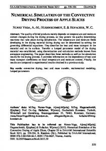
Figure 11. Flow coefficient varies with the pressure ratio. The calculation results show that the three flow coefficients change little with the pressure ratio. Under the given conditions, the flow coefficient of the circular leakage model can be taken as 0.35-0.4, the flow coefficient of cuspate leakage model can be taken as 0.7-0.8, the flow coefficient of the flat leakage model can be taken as 0.08-0.12. For the model of this paper, the flow coefficient of the uspate leakage model is 0.4, the flow coefficient of cuspate leakage model is 0.75, the flow coefficient of the flat leakage model is 0.08. 4. The equation solution and the results analysis 4.1. The equation solution The mathematical equations describing the working process of the twin-screw vacuum pump have been established, and then were performed numerically by means of the Runge-Kutta 4th order method, with appropriate initial and boundary conditions. First, the no-leakage process was calculated on the assumption that the model was thermally insulated, and each thermodynamic parameter changing with the rotational angle in the whole working process was determined, including initial pressure and initial temperature. Second, considering the leakage influence, the procedure ran with the initial pressure and temperature as given values. Then new pressure and temperature were obtained by the iterative computations. If the relative error between the new values and the last values of pressure and temperature was greater than ε, then the procedure continued to run with the new values of pressure and temperature as given values until the relative error was less than ε. 4.2. The result of the analysis Based on the mathematical model of the working process in the screw vacuum pumps, the p-θ diagrams which describe the pressure changing with the rotary angle were calculated at three different rotational speeds of 2400r· min-1, 2700r· min-1 and 3000r· min-1 when the suction pressure was 3kPa, as shown in Figure 12. Figure 12 indicates that the pressure varies greatly between the ideal condition and the actual condition. The main reason is that the mesh clearance of the oil-free twin screw vacuum pump is relatively large, plus the clearance gap seal, so that the leakage is more serious. The pressure curve is roughly divided into two sections at the point of 1500 degrees. Before 1500 degrees, the pressure rises slowly, and there is no significant difference in pressure at different speeds; after 1500 degrees, the control volume reaches the exhaust end and the exhaust pressure is 1.0 bar, the adjacent control volumes have a larger pressure difference and there is a large leakage. The exhaust pressures under these three speeds were 103.5kPa, 87.0kPa and 71.5kPa respectively, which shows that the leakage can be reduced greatly by increasing the speed. There is the
8
10th International Conference on Compressors and their Systems IOP Publishing IOP Conf. Series: Materials Science and Engineering 232 (2017) 012027 doi:10.1088/1757-899X/232/1/012027 1234567890
phenomenon of over compression at the speed of 2400r· min-1 which means the pressure is already greater than the back pressure of the system before the control volume connected with the exhaust port. The simulation results have guiding significance for the design of the screw pitch and the exhaust port.
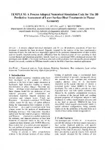
Figure 12 P-θ diagrams at different rotational speeds. The figure 13 shows p-V diagrams turned by the p-θ diagrams, and the working process inside the vacuum pump can be seen clearly. There is a constant volume stage in the working process, the reason for the increasing pressure is the leakage.
Figure 13 P-V diagrams at different rotational speeds. According to the p-V diagram, the pressures of three speeds changed in the same trend, the leakage reduced as the speed increased, and the pressure rose slower and slower. Because of the constant volume stage there is a segment in which pressure rises perpendicularly. Overall, the variable pitch rotor is beneficial to seal, and reduce the leakage from the exhaust port to the suction port. The power consumption under different conditions can be seen directly from the p-V diagram, and the power consumption at high speed is relatively low. 5. Conclusion The working process characteristics of the oil-free twin screw vacuum pump were analyzed, including suction, compression, transmission and exhaust. The basic control equations of the working process were established according to the energy conservation equation and the basic principle of variable mass thermodynamics, also considering the effect of leakage on the process. The main conclusions can be summarized as following: (1)The thermodynamic model describing the working process of twin-screw vacuum pump was established according to the basic principle of variable mass thermodynamics, the energy conservation equation, the mass conservation equation and the gas state equation.
9
10th International Conference on Compressors and their Systems IOP Publishing IOP Conf. Series: Materials Science and Engineering 232 (2017) 012027 doi:10.1088/1757-899X/232/1/012027 1234567890
( 2 ) The leakage through the sealing line and the meshing line were analyzed, and the corresponding mathematical model was established. ICEM®was used to build the structure grid of the geometric model, then the flow coefficients of each path were obtained by Fluent®. The flow coefficient can be seen as a constant for the leakage models with a given geometry. For the model of this paper, the flow coefficient of the cuspate leakage model is 0.4, the flow coefficient of the cuspate leakage model is 0.75, the flow coefficient of the flat leakage model is 0.08. (3)The Runge-Kutta method was applied to calculate the control equations of the working process in the vacuum pump. The p-θ diagrams at three different rotational speeds of 2400r· min-1, -1 -1 2700r· min , 3000r·min were calculated when the suction pressure was 3kPa. The results show that the pressure rise is small in the first half of the screw rotor and the pressure rise is larger in the second half. There is the phenomenon of over-compression at the speed of 2400r· min-1. It is found that The calculated results are instructive to the design of the screw rotor. Acknowledgements The authors would like to express appreciation to the Department of Compressor Engineering of the Xi’an Jiaotong University for supporting and encouraging our efforts.
References [1]
Lee B, Yanagisawa T, Fukuta M and Choi S 2002. A study on the leakage characteristics of tip seal mechanism in the scroll compressor. 16th Int. Compressor Engineering Conf. at Purdue pp1586-94. [2] Z H Fong, F C Huang 2006. Evaluating the interlobe clearance and determining the sizes and shapes of all the leakage paths for twin-screw vacuum pump. Mechanical engineering science, 220 Part C pp499-506. [3] FeiChuan H 2007. Study on the leakage evaluation of the non-conjugate rotor profiles for a twin-screw vacuum pump, National Chuang Cheng University. [4] Yu Z 2008. The structure and properties of the rotors of dry screw vacuum pump. Northeastern University. [5] Ohbayashi T, Sawada T, Hamaguchi M and Miyamura H 2001. Study on the performance prediction of screw vacuum pump. Applied Surface Science,169 pp768-771. [6] Stramann D, Kauder K 2008. Operating performance of screw vacuum pumps. Vacuum in Forschung and Praxis, 20 pp19-25. [7] Yang L, Bei G, Maofei G 2015. Study on design of totor profile for the twin screw vacuum pump with single thread tooth. IOP Conf. Ser.: Mater. Sci. Eng. 90 012007 [8] Yang L, Bei G, Ruixin Z 2015. Numerical simulation for working process in twin screw vacuum pump. Journal of Xi’an Jiaotong University, 49(7) pp67-71. [9] Egashir K, Shoda S, TochikAWA T and Furukawa A 1998. Backflow in twin-screw-type multiphase pump. SPE production & facilities 13(01) pp64-69. [10] Feng C, Ziwen X, Pengcheng S 2001. Study on the working process of twin screw multiphase pump. Chinese Journal of Mechanical Engineering ,37(3) pp73-77.
10