grazing collision, where the drops coalesce and then stretch apart ... example, the total surface area of sprays depends on the size of the ... average effects of the unresolved scales are. 'Graduate ..... 'The solid curve in (a) is the velocity in tile.
AlAA 94-0835 Numerical Simulations of Drop Collisions M.R.H. Nobari The University of Michigan Ann Arbor, MI and G.Tryggvason Institute for Computational Mechanics in Propulsion, Lewis Research Center Cleveland, OH and The University of Michigan Ann Arbor, MI
32nd Aerospace Sciences Meeting & Exhibit January IO-13,1994/ Reno, NV For permission to copy or republish, contact the American Institute of Aeronautics and Astronautics 370 L'Enfant Promenade, S.W., Washihgton, D.C. 20024
NUMERICAL SIMULATIONS OF DROP COLLISIONS "--
M.R.H. Nohari* The University of Michigan Ann Arbor, MI and G. Tryggvasont Institute for Computational Mechanics in Propulsion, Lewis Research Center, Cleveland, OH and
The University of Michigan Ann Arbor, MI
Abstract
x-
incorporated into the equations used to predict the large scale behavior. Many spray models (see Heywood', for a discussion and references) use point particles to represent the drops. The drop motion is related to the fluid flow by empirical laws for drag, heat transfer and combustion. Often it is possible to focus on the dynamic of a single drop and how it interacts with the surrounding flow. When the number of drops per unit volume is high, however, it is necessary to account for the interactions between the drops and their collective effect on the flow. To account for drop collisions, models must contain "collision rules" that determine whether the drops coalesce or not. These rules are usually based on experimental investigations of binary collisions of drops, but thc small spatial and temporal scales make detailed experimental measurements difficult and usually [he record consist of little more than photographs or a video tape. Since the collision process generally involves large drop deformation and rupture of the interface separating the drops, it has not been amenable to detailed theoretical analysis. Previous studies are therefore mostly experimental, hut sometimes supplemented by greatly simplified theoretical argument.
Three-dimensional simulations of the off-axis collisions of two drops are presented. The full Navier-Stokes equations are solved by a FrontTrackingFinite-Difference method that allows a fully deformable fluid interface and the inclusion of surface tension. The drops are accelerated towards each other by a body force that is turned off before the drops collide. Depending on whether the interface between the drops is ruptured or not, the drops either bounce or coalesce. For drops that coalesce, the impact parameter, which measures how far the drops are off the symmetry line, determines the eventual outcome of the collision. For low impact parameters, the drops coalesce permanently, hut for higher impact parameters, a grazing collision, where the drops coalesce and then stretch apart again is observed. The results are in agreement with experimental observations.
Introduction
The dynamic of fluid drops is of considerable importance in a number of engineering applications and natural processes. The combustion of fuel sprays, spray painting, various coating processes, as well as rain, are only a few of the more common examples. While it is usually the collective behavior of many drops that is of interest, often it is the motion of individual drops that determines the large scale properties of the system. Thus, for example, the total surface area of sprays depends on the size of the individual drops as well as their number density. Computational models for engineering predictions of spray combustion generally do not resolve the motion of individual drops and must rely on "subgrid" models where the average effects of the unresolved scales are
Two recent experimental investigations of drop collisions can be found in Azhgriz and Poo2, and Jiang, Umemura and Law3 who show several photographs of the various collision modes for both water and hydrocarbon drops. These, and other experimental investigations have provided considerable information and, in particular, it is now understood that the outcome of a collision can he classified into about five main categories. For head-on collisions we have four main categories: bouncing collision, where the drops collide and separate, retaining their identity; coalescence collision, where two drops become one; separation collision, where the drops temporarily become one hut then break up again; and shattering collision, where the impact is so strong that the drops break up into several smaller drops. These categories survive for off-axis collisions, hut a fifth one,
'Graduate Student, Department of Mechanical Engineering ?Associate Professor, Department of Mechanical Engineering
1
1
\.
.,
L-'
rectangular box and the drops are initially placed near each end of the domain. A force that is turned off before the drops collide, is applied to drive them together initially. Generally, the density and viscosity of the ambient fluid are much smaller than of the drop fluid and thus have only a small effect on the results. While it is therefore often sufficient to solve only for the fluid motion inside the drop, here we solve for the motion everywhere, both inside and outside the drops. The NavierStokes equations are valid for both fluids, and a single set of equations can be written for the whole domain as long as the jump i n viscosity and density is correctly accounted for and surface tension is included: -+ apii v .pTiii = -vp + f x
grazing or stretching collision, appears. Here, the drops coalesce upon contact, but are sufficiently far apart so that they continue along the original path and separate again. The form of the collision depends on the size of the drops, their relative velocities, their off-axis position and the physical properties of the fluids involved. For a given fluid, some of these collision regimes are not observer. Water drops, for example, do not show bouncing. (Jiang er d 3 ,state that they also did not find reflective collision for water drops. This is apparently due to a limited parameter range studied by them as the experiments by Azhgriz and Poo2, show.) Other investigations of drop collisions may be found in Bradley and Stow4, and Podvysotsky and Shraibers, for example. The major goal of these investigations has been to clarify the boundaries between the major collision categories and explain how they depend on the parameters of the problem. Simple models used to rationalize experimental findings have been presented by Park and Blaifi, Ryley and Bennett-Cowell', Brazier-Smith et a1.8, Azhgriz and Poo2, and Jiang, Umemura and Law3.
at
+ v +(vu+ E T ) + F&
Here, ii is the velocity, p is the pressure, and p and p are the discontinuous density and viscosity fields, respectively. Fo is the surface tension force and f, is a body force used to give the drops their initial velocity. Notice that the surface tension force has been added as a delta function, only affecting the equations where the interface is. The detailed form of Fa will he discussed below. The above equations are supplemented by the incompressibility conditions V.ii=O which, when combined with the momentum equations leads to a non-separable elliptic equation for the pressure. We also have equations of state for the density and viscosity:
In principle, numerical solutions of the Navier-
\,'
- Ff).
Strokes equations, where all scales of motion are fully resolved, can provide the missing information, but various numerical difficulties associated with moving boundaries between two fluids have made detailed simulations difficult in the past. Nevertheless, several authors have computed the axisymmetric head-on collision of drops with a wall. The earliest work is Foote' who followed the evolution of a rebounding axisymmetric drops at low Weber number using the MAC method. More recent computations work can be found in Fukai et all0 who use a moving finite element method. We have recently conducted a numerical study of the head-on collision of two axisymmetric drops, see Nobari, Jan and Tryggvason", where we examined the boundary between coalescing and reflecting collision for equal size drops. Here, we present numerical simulations of three-dimensional, off-axis collisions, where the full Navier Stokes equations are solved to give a detailed picture of the flow during collision.
aP -+ u . vp = 0 at
@ -+ u . vp = 0. at
These last two equations simply state that density and viscosity within each fluid remains constant. Nondimensionalization gives a Weber and a Reynolds number defined by:
R e = -Pd uD I. I d In addition, the density ratio r = p d I p , and the viscosity ratio L = p,, I po must be specified. Here, the subscript d denotes the drop fluid and o W e = -P d D U 2
1
U
Formulation and Numerical Method The numerical technique used for the simulations presented in this paper is the Front TrackingFinite Difference method of Unverdi and Tryggvason"- 13. Since the procedure has bee described in detail before, we only outline it briefly here.
the ambient fluid. In off-axis collisions, the drops approach each other along parallel lines that are some distance apart. If this distance is greater than the drop diameter, D, the drops never touch and no collision takes place. If this distance is zero, we have a head-on collision. To describe off-centered
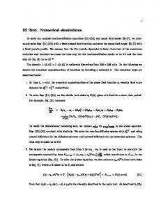
The physical problem and the computational domain is sketched in Figure 1. The domain is a
2
I
I
Figure 1. The computational domain and the initial conditions. The drops are initially two and a half diameter apart. similar to the one discussed by Unverdi and Tryggvasonl2, that spreads the density jump to the grid points next to the front and generates a smooth density field that changes from one density to the other over two to three grid spaces. While this replaces the sharp interface by a slightly smoother grid interface, all numerical diffusion is eliminated since the grid-field is reconstructed at each step. The surface tension forces are computed from the geometry of the interface and distributed to the grid in the same manner as the density jump. Generally, curvature is very sensitive to minor irregularity in the interface shape and it is difficult to achieve accuracy and robustness at the same time. However, by computing the surface tension forces directly by
collision a new nondimensional parameter, usually called the impact parameter, is required in addition to the Weber and the Reynolds number defined earlier. This parameter is usually defined as
I=X
x
D
where is the perpendicular distance between the lines that the drops move along before collision.
-
.,
The force used to drive the drops together initially is taken as jx= c ( P - P , ) ( x - x , ) so the force acts only on the drops. Here C is an adjustable constant and xc is midway between the drops. This force is turned off before the actual collision takes place. Initially, the drops are place with their centers two and a half diameter between them, and C is varied to give different collision velocities.
F, = o $ i x i i d s we ensure that the net surface tension force is zero,
or:
$ ortnds = 0
Here, iiis the outward normal, i a tangent vector to the boundary curve for each element and K is twice the mean curvature. This is important for long time simulations since even small errors can lead to a net force that moves the drop in an unphysical way.
To solve the Navier Stokes equations we use a fixed, regular, staggered grid and discretize the momentum equations using a conservative, second order centered difference scheme for the spatial variables and an explicit second order time integration method. The pressure equation, which is non-separable due to the difference in density between the drops and the ambient fluid, is solved by a Black and Red SOR scheme. Other versions of our code use a multigrid iteration. The novelty of the scheme is the way the boundary, or the front, between the drops and the ambient fluid is tracked. The front is represented by separate computational points that are moved by interpolating their velocity from the grid. These points are connected by triangular elements to form a front that is used to keep the density and viscosity stratification sharp and to calculate surface tension forces. At each time step information must be passed between the front and the stationary grid. This is done by a method
As the drops move and deform, it is necessary to add and delete points at the front and to modify the connectivity of the points, to keep the front elements of approximately equal size and as "well shaped" as possible. This is described in Unverdi and Tryggvason.'2 When the drops are close, we rupture the interface, in several of our computations, by removing surface elements that are nearly parallel and reconnecting the remaining ones to form a single surface. Here, this restructuring of the interface is done at prescribed time if the interfaces are close enough. While this rather arbitrary (and we have simply selected the
i-~
3
Figure 2. Coinparison between a fully three-tiimensional simulation (right) and results obtained by ai! axisymmetric code (left). The initiai conditions are shown iit the top of each column and the solution is then shown at three eqoispaced times for each run. Pime when the drops iook close enough) this allows some control over the dynamic of the rupture, as compared with numerical methods where t.he front i s not tracked ontl the film would always rupture once it is thinner than a few grid spaces. For a more detailed discnssion of this point see Nobari, Jan, and Tryggvason&.
For the computations presented here, W e = 2 3 ; Re-68, r 4 0 , and , I S O , bot the impact parameter, I , is varied. The computational domain is rcsolvcd by a 32 by 32 by 64 cubic mesh and the drop diameter i s 0.4 times the shorter dimensioo.
The meiliod and lhe code has been tested in various ways, such as by exteasivc grid refinement studies, conipmison with other published work and analytical solutions. It has also been used to investigate a number of other multifloid problems. Xn addition to the computations of head-on collisions 01‘ drops by Nobari, Jan and I ryggvason4*1Jiivcrdi and ‘I’ryggvasonl3 simulated the collision of fully three dimensional bubbles, Ervinf4investigated the lift of deformable bubbles rising in a shcar flow (sec also Esmaeeli, Ervin, and Tryggvason’s, Sari aiid Tryggvason‘6 examincd thc cffcct of contaminants on the rise of buoyant buhblcs and Nobari and T r y g g v a s ~ n follovid ’~ the coalescence oi drops of different sizes. Nas and Tryggvescinl* piesentetf simulation of theriual migration of many ?wo dimensional bubbles.
While we have done extensive checks of the accuracy of our axisymmetric code, the lhrcediniensional code has not been tested as thoroughly. We have therefore conducted a few calculations oi head-on collisions where the results koni the threedimensional simulations can be compsrcd with the axisyinmetric results. Figure 2 shows this comparison. The axisymmetric results are to the left and the fully three dimensional rcsulis io the right. The initial conditions are shown at the top of each colunin and the drops are then shown below at equispacctl times. The force that acts on the drops initially is runied off before impact (jus1 before the second frame). As the drops collide they becomc flatter, and the ambient fluid between the is pushed away, leaving a thin filtn of fluid between the drops. Here, this film i s not removed and the drop
I .
Figure 3. The :;-position of ihc center of inass of drop versus i.im:, as computed by Boih the fully iiuec--diniensionalcode arid an axisymnietric one, Tor two different resolirtiotis.
oiie
ti~ereforerebound, recovering their spherical shape. Obviously, the results are i n good agreement. Figure 3 shows a more quantitative comparison, whme we plot the .x--positionof the center of tnass for the drops i n figure 2, as well as for drops computed on a coarser grid (16 hy 16 by 32). The agrcemcot .is reasonably good, although the coarse grid xesiilts %e riot in as good agreement with each ofheras the finer grid n:sults are.
.
.
In figuve 4, the off-ax.is collision of IWO drops, for 1d.75, is shown. The pair is shown at several equispaceti times; beginning with the initial position at the top 01 the figure. Once the drops have the desired velocity. around i,he tliird frame from the top, thc form that is applied to drive the drops together i s turned off. The drops continuc to move togcther, arid i i i the fourth franc they have collideti. deforming as they do 50. Since the collision parameter is relatively high. the drops slide past cach other antl coiitiiiue along rheir original path. The botiorn four frames show thc motion of thc tlrops after thr: collision. Ihriitg thc collision the drops become nearly Rat where they face each other, and as the drops slide past each other the fluid hyer between the drops becomes progressively tliiimcr. If i t hecomes thin enough it should rupture, but liere we have not allowed that to happen. (As seen in figure 6, rupture of this film will change the resulting evolution considerably.) i n figure 5 , the velocity coinponcnts of the cfmter of iiiass of one of tile tlrops, (a), and the !Gneiic antl the siirfdce tension energy. ._.(I)).. . Is dotted versus time. 'The solid curve in (a) i s the velocity in tile horizontal direction. It increases 8s the force accelerates ihe drops together, and then deciease~ slightly due to the drag from the outer fluid after the force is IU~IIBCI off. When the drops actuallv collide, it is r e d ~ ~ c e dinore rapidly, hiat ~
Figure 4. Bouncing collision. Here H . 7 5 and the drops are not allowed 1.0 coalesce. The initial conditions we shown at the top and the drops are then shown cvcry 0.42 rime unit.
right column I=0.825. The film between the drops is ruptured at time 0.46 for both runs. In these computations we put t=O.O when the distance between the center of the drops is one diameter. For the low impact parameter case, the drops deform considerably during the initial impact, as observed for head-on collisions, hut the impact parameter is sufficiently large so the drops still slide past each other. As the film is ruptured and the drops coalesce the momentum of each drop is sufficiently large so the large combined drop continues to elongate Eventually, however, surface tension overcomes thc stretching and the drop is pulled into a spherical shape. Due to the velocity of the drops that coalesced, the combined drop rotates. While the low impact parameter drops are in many way similar to drops undergoing a head-on collision, the high impact parameter drops in figure 6h deform only slightly as they collide. When thc interface between them is ruptured, they have nearly passed each other and after rupture their momentuni is sufficiently large so they continue along their original path and stretch the fluid column connecting them until it is near breaking. We have not written the software necessary for rupturing the ,-----_____ filament connecting the drops and therefor must m - 1 50 I IO 2 IO stop the computations at this point. Notice, that tic&) the coalesced drop rotates, as the low impact Figure 5. (a) Center of mass velocity of one drop parameter one did, although much less. from the computation In figure 4. (h) Kinetic and surface tension energy of one drop. In figure 7, the surface tension energy, the kinetic energy and the total energy of the drops from figure eventually resumes a nearly constant decay rate after 6 are plotted versus time. Initially, the kinetic the collision is over. The velocity component in energy is increased by the force that accelerates the the vertical direction (short dashes) is non zero only drops together. Since this force is not constant (it during the actual collision. The kinetic energy in increases linearly with distance from the center of (h) shows similar behavior as the velocity: it the computational box) the increase is not quadratic decreases slowly after the force is turned off, more as for the computations reported in Nohari, Jan, and rapidly during collision and then resumes slow Tryggvason”. After the force has been turned off, decay. The surface tension energy rises during the the drops move a short distance before colliding collision as the drop deforms, thus contributing to Since the ambient fluid has a finite viscosity, the reduction in the kinetic energy. Notice that the kinetic energy is dissipated due to friction and the drop oscillates slightly after the collision as seen in drops slow down. As the drops come in contact, thc the surface tension energy plot. kinetic energy of the low impact number drops decreases rapidly, but the high impact number drop? Although bouncing is observed for real drops, it is are not affected to any significant degree. Similarly, actually a relatively rare outcome of a collision, the surface tension energy of the low impact only seen when the drop deform and trap fluid number drops increases and the drops deform, but between them and the velocity is sufficiently large the surface tension energy of the other drops hardly so the film does not have time to drain before the increases at all since the drops remain almost drops rebound. To investigate the behavior of drops spherical. When the film between the drops is that coalesce, we have written software to ruptured, part of the drops surface is removed and automatically remove the front bounding the thin the surface energy reduced. This reduction is larger film between the drops at a prescribed time and for the low impact number drops since the area allow the drops to coalesce. Figure 6 shows the removed is larger. Initially, the kinetic energy of results of two computations where the drops the high impact number drops is nearly unaffected coalesce. All parameters are the same as in figure 2, (and continues to he dissipated at the same rate as except that in the left column I=O.50, and in the -Y)
6
Figure 6. Coillesciiig collisions. The initial conditions are shown at the top of the figure aiid the pair is rhcn shown every 0.4% iiinc units. The film is ruptimd at t=0.46 in both cases, but the impact paramcicr is different for the two runs. In the left column 14.5, and 1-0.825 iii the right onc. For the low impact parameter, the drops coalesce pennanzntly, but For thc higher impact pammetei. they separate again.
7
shown in figure 5 , we have conducted two other calculations at different impact parameters. The runs that lead to a coalesced drops are shown by black squares and those leading to grazing collision as open squares. We have also plotted the experimental results of Jiang et all, for the boundary between these two collision modes for We=23. Their results d o not extend down to the Reynolds number simulated here, but since the boundary is only weekly dependent on the Reynolds number is seems save to extrapolate their results to our Reynolds number. The dashed line shows this extrapolation, showing that the numerical results are consistent with the experiments.
Conclusion
m-2 m
The purpose of this paper is to demonstrate the feasibility of accurate numerical predictions of fully three-dimensional off-axis collisions of two drops. To do so, we have simulated a few cases, both with and without rupturing of the interface separating the drops. Although the rupture of the film between the drops is done in an ad hoc, way, the result are in reasonably good agreement with experimental observations. For exact predictions of the boundary, a more accurate criteria for the rupture time'9 would have to be used. These computations, which require about ten hours on a CRAY-XMP, are done on a relatively coarse mesh and are therefore limited to relatively small Reynolds and Weber numbers. Nevertheless, they do demonstrate well the capability of the method.
I
/ -54
t/i'dE'J
1IO
rm
Figure 7. The energies for the drops in figure 6. (a) k 0 . 5 , (b) I=0.825. The total energy, the surface energy and the kinetic energy of the drops are plotted versus time. before the drops collide), but as the coalesced drop starts to stretch and the surface tension energy to increase, the kinetic energy drops sharply. As the filament between the drops starts to neck down, the increase in surface area stops and the kinetic energy levels off. For the low impact number drops, the rupture takes place near the point of maximum deformation and surface energy is initially converted into kinetic energy as the drops adjusts to the new shape. The momentum of the drop before impact is, however, sufficiently large so the drop is stretched as the fluid of the original drops continue along the paths they were following before collision. This leads to an increase in surface tension energy and decrease in kinetic energy. When the surface tension energy reaches maximum the kinetic energy is not zero due to the finite rotational motion of the coalesced drop. Eventually, the coalesced drop oscillates.
Acknowledmnent We would like to acknowledge discussions with Dr. D. Jacqmin at the NASA Lewis Research Center. Pan of this work was done while one of the authors (GT) was visiting the Institute for Computational Mechanics in Propulsion at NASA Lewis. This work is supported in part by NASA grant NAG31317, and NSF grant CTS-913214. Some of the computations were done at the San Diego Supercomputing Center which is funded by the National Science Foundation.
Reference2 1. J. B. Heywood. Internal Combustion engine Fundamentals. McGraw-Hill, (1988). 930 pages. 2. N. Ashgriz and J.Y. Poo. Coalescence and separation in binary collisions of liquid drops. J. Fluid Mech. 221 (1990), 183-204.
For modeling of droplet collisions, the major question is whether the collision results in a single drop or not. Figure 8 shows our computations in the I-Re plane. In addition to the computations L.
X
I .oo
Computational Results, Re=68, We=23
0.75 L
-
9 0
_ _ _ _ _
E m
L
2
0.50
-
c 0
::
-
Grazing Collision
a
Permanent Coalescence
E
0.25
0.00
0 Experiments
We=23
I
1
0
100
I
I
200 300 Reynolds Number
I
400
500
Figure 8. The boundaries between coalescing and grazing collisions in the Re-I plane for We=23. The solid circles, connected by a line, are experimental data from Jiang et a P T h e squares are computed results.
.
3 . Y.J. Jiang, A. Umemura, and C.K. Law. An experimental investigation on the collision behavior of hydrocarbon droplets. J. Fluid Mech. 234 (1992), (71-190. 4. S.G. Bradley and C.D. Stow. Collision between liouid droDs. Phil. Trans. R.Soc. Lond. A 287 (l$78), 635-678. 5. A.M. Podvysotsky and A.A. Shraiber. Coalescence and breakup of drops in two phase flows. Intl. J. Multiphase Flow 10 (1984). 195209. 6. J.Y. Park and L.M. Blair. The effect of coalescence on drop size distribution in an agitated liquid-liquid dispersion. Chem. Engng. Sci. 30, 1057-1064. 7. D.J. Ryley and B.N. Bennett-Cowell. The collision behavior of steam-borne water drops. Int. J. Mech. Sci. 9 (1967), 817-833. 8. P.R. Brazier-Smith, S.G. Jennings and J. Latham. The interaction of falling water drops: coalescence Proc. R. SOC.Lond. A 326 (1972), 393-408. 9. G.B. Foote. The Water Drop Rebound Problem: Dynamics of Collision. J. Atmos. Sci. 32 (1975), 390402. 10. J. Fukai, 2. Zhao, D. Poulikakos, C.M. Megaridis, and 0. Miyatake. Modeling of the deformation of a liquid droplet impinging upon a flat surface. Phys. Fluids A, 5 (1993), 2589-2599.
11. M.R.H. Nobari, Y . J . Jan, and G . Tryggvason. Head-on collision of drops-A numerical investigation. Submitted for publication (1993). 12. S.O. Unverdi and G . Tryggvason. A Front Tracking Method for Viscous Incompressible Flows. J. Comput. Phys., 100 (1992) 25-37. 13. S.O. Unverdi and G. Tryggvason. Multifluid flows. Physica D 60 (1992) 70-83. 14. E.A. Ervin: Full Numerical Simularions of Bubbles and Drops in Shear Flow, Ph.D. Thesis, The University of Michigan, 1993. 15. A. Esmaeeli, E.A. Ervin, and G. Tryggvason: Numerical Simulations of Rising Bubbles. To appear in Proceedings of the IUTAM Conference on Bubble Dynamics and Interfacial Phenomena (Ed.: J.R. Blake) 16. Y.-J. Jan, and G. Tryggvason: Computational Studies of Contaminated Bubbles. Submitted for publication (1993). 17. M.R.H. Nobari and G. Tryggvason: Coalescence of Initially Stationary Drops. Submitted for publication (1993) 18. S . Nas and G. Tryggvason: Computational Investigation of the Thermal Migration of Bubbles and Drops. 1993 ASME Winter Annual Meeting. 19. D. Jacqmin and M.R. Foster. The evolution of thin films generated by the collision of highly deforming droplets. Submitted for publication (1993).
9