are always occluded by virtual objects. We call this the. âocclusion problemâ. As figure 1 shows this problem re- duces the illusion that the virtual objects are part ...
Occlusion Detection of Real Objects using Contour Based Stereo Matching Kenichi Hayashi, Hirokazu Kato, Shogo Nishida Graduate School of Engineering Science, Osaka University,1-3 Machikaneyama-cho, Toyonaka, Osaka, Japan {hayashi,kato,nishida}@nishilab.sys.es.osaka-u.ac.jp
Abstract In Augmented Reality, the occlusion between virtual and real objects has to be managed correctly, so that users can look at the natural scene. In order to overcome this problem, the depth of the real world from the user’s viewpoint is employed. However, if the system is used in an environment including moving or deformable objects, the depth has to be measured in real-time. In this paper, we propose a method for real-time stereo matching using a contour based approach to acquire the accurate depth of the boundary of real objects. Keywords: augmented reality, occlusion, contour based stereo matching, video see-through
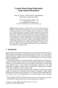
1. Introduction Augmented Reality (AR) interfaces typically involve the real time overlay of virtual images on the real world. Consistency between the virtual objects and the real world has to be managed correctly so that users feel that the combined scene is natural. Geometrical consistency is especially important. There are two geometrical consistencies to be managed in Augmented Reality. The first is the consistency of the coordinate systems of the real and virtual worlds. In order to appear part of the real scene the virtual imagery needs to have the same coordinate system. The second is correct occlusion between virtual and real objects. However, in current video see-through AR systems virtual objects are usually rendered on the video image without using depth information from the real scene, so real objects are always occluded by virtual objects. We call this the ”occlusion problem”. As figure 1 shows this problem reduces the illusion that the virtual objects are part of the real world scene and affects the user’s recognition of the geometrical relationship between real and virtual objects. Moreover, in the case of collaborative AR interfaces, when virtual objects incorrectly cover parts of the user’s body this can affect communication between the users. So, in an AR interface, it is important to represent correct occlusion between virtual and real objects. In this paper we describe a contour-based technique that can be used to calculate correct occlusion in real-time.
2. Related Work There have been a number of earlier efforts to address the occlusion problem in AR interfaces. Yokoya et al. acquire depth information of real objects by using stereo matching [1]. In this method, to reduce the computational cost, stereo matching is limited to the region where virtual objects should be rendered. However, this method had prob-
Figure 1: Occlusion problem in Augmented Reality
lems with its accuracy. Although detailed depth information is found in a limited region, stereo matching is not so accurate so that the boundary between the real and virtual images is not represented correctly. Kim et al. also used stereo matching to estimatethe depth of the real environment [2]. In their method, the depth of boundary of real objects is estimated to find the natural occlusion between real and virtual objects. However, their technique is computationally expensive and difficult to process in real-time. Ohta et al. proposed a client-server depth sensing method [3]. Clients can obtain the depth of the real environment from a large depth sensing device (server). This device provides accurate depth information in real-time. However, since the viewpoint of the server is different to that of the clients, there may be regions in the clients view where depth information has not been acquired. Fuhrmann et al. proposed the method using the 3D models of real objects that called ”phantoms”, rendering them in the same position that real objects exist to solve the occlusion problem [4]. This method will work when the target real objects are rigid. However, it cannot be applied to deformable objects such as human hands, Lepetit proposed a contour based approach [5]. They obtain the depth information of real objects by estimating their contours. Since the contour of a real object will change in each frame, they manually define the contour of object in key frames and use this to estimate the object contour in the current frame. However, their algorithm is impossible to run in real-time and cannot be applied to deformable objects. Setohara et al. proposed a method based on background subtraction to extract moving objects in real environment [6]. As part of the background image, they use a marker pattern that is used for camera pose estimation. However, since the depth information of moving objects is not acquired, it is impossible to find the correct occlusion. Moreover, moving objects can only be detected in the region with the marker pattern.
3. Our Method In this paper, we propose a new technique to resolve the occlusion problem in real-time. The main goal of this method is to resolve the case when a user’s hands are occluded by virtual objects in a tabletop AR system. Our method consists of 2 steps: 1. Object Segmentation: We detect moving objects from the dynamic background by extending the method proposed by Setohara et al. [6]. 2. Depth Sensing: We perform depth sensing in just the region around the moving object in the real environment. This is possible for tabletop AR systems because the 3D information of the static environment can be found from an earlier offline stage. Under this condition it is possible to reduce the computational cost of stereo matching and also provide stable stereo matching. The method proposed by Setohara et al. is based on background subtraction, and can be applied to dynamically changing backgrounds. However, in their work moving objects can only be detected in the region in front of a marker pattern. Our method use the pictures of real environment called ”key frames”, and so extends the area in which moving objects can be detected to the general region outside the marker pattern. We will explain the details of this in the next section. Once segmented from the background, the depth of moving objects is found by stereo matching. We assume that what is important for resolving the occlusion problem is not finding a detailed depth map, but representing the natural occlusion between real and virtual objects. So we attach the highest importance to correctly finding the boundary of real objects. So, stereo matching is processed only at the boundary of moving objects found from step one. This process is explained in more detail in section 5. We will describe experimental results in section 6 and discuss our method in section 7.
Figure 2: The moving objects extraction method by Setohara et al. be taken from all possible camera positions, which is impossible. In our work we generate a background virtual camera image taken from current viewpoint dynamically and use this for background subtraction. In the next section, we explain the algorithm to generate a virtual viewpoint image using a finite number of offline images taken from a particular position.
4.1. Keyframe based approach To generate the background virtual viewpoint image, we use images taken from particular positions in an earlier offline stage. We call these images ”keyframes”. Figure 3 is an example of a set of keyframes. These images are captured stored in the offline stage before the user starts the real time AR application. For each camera image we also store a transformation matrix Mk that transforms the marker coordinate system to the current camera coordinate system, and a projection matrix P .
4. Moving Objects Detection Setohara et al. proposed a method to detect moving objects in front of a set marker pattern, using the maker pattern as a background image [6]. For example in figure 2, the marker pattern (Fig.2-a) is transformed in compliance with the current viewpoint (Fig.2-b). Moving objects are detected by comparing camera image (Fig.2-c) and this transformed pattern. However, moving objects can only be detected in front of the marker pattern. Moreover, in this method, it is assumed that the background pattern is composed of a black and white image. However, the color value of marker patterns actually seen in the camera image is liable to change depending on the camera characteristics, illumination condition and observation position. So if such an ideal black and white pattern is used for background subtraction, detection error may occur. However, this error can be reduced if an earlier picture taken by a camera from the same position as the current camera can be employed for background subtraction. This picture is assumed to just have the background objects in it and none of the moveable or foreground objects in it. In order for this to be useful background pictures would need to
Figure 3: Keyframes Let X= (x, y, z, 1)′ be a 3D coordinate of the marker coordinates. Let xk be 2D coordinate of a pixel that X is projected on the keyframe image plane. xk can be written as following equation using Mk , P and X.
(
s t q
) =
P ´ Mk ´ X
( xk
=
s q t q
(1)
) (2)
Where (s, t, q)′ is a vector in the projective space. As a result, the 2D coordinate on a keyframe image xk is acquired via perspective transformation. Similarly, the 2D coordinate on a current camera image xc that corresponds to xk is acquired from equation (1) (2) using Mc instead of Mk . Where, Mc is a transformation matrix between a marker coordinate system to a camera coordinate system at current camera position (Fig.4). Once xk and xc are acquired, it becomes possible to compare a pixel value of the keyframe image at xk , Ik (xk ) and a pixel value of the current camera image Ic (xc ). It is possible to employ Projective Texture Mapping [7] [8], which is a real-time rendering technique in Computer Graphics and Pixel Shader [9] to acquire Ic , Ik , and compare with them effectively.
Ib0
=
Ic0
=
α
=
d
=
Ib ∥ Ib ∥ ( Ic ´ Ib0 ) Ib0 ∥ Ic0 ∥ ∥ Ib ∥ ∥ Ic0 ` Ic ∥
The pixel is part of a moving object Else The pixel is in the background or shadows
Figure 4: Pixel matching between keyframe and camera image
4.2. Extend a detectable region
(a) 3D model of real environment
4.3. Robust background subtraction method In this section, we propose a robust algorithm that compares the corresponding pixels between the camera image and keyframe image to detect moving objects. Moving objects are detected by background subtraction where a keyframe image is used as background image. However, if a simple algorithm such as SAD (Sum of Absolute Difference) is employed, shadows of moving objects may also be detected as moving objects. To avoid this problem, we employ the following algorithm.
(4) (5) (6)
Where, Ic and Ib indicate a pixel value of the camera image and background image respectively, represented as a 3 dimensional vector consisting of an R, G, and B channel. Ib0 is a normalized vector of Ib and Ic0 is a vector formed when Ic is projected into Ib space. The value α indicates a ratio of brightness, and d indicates a difference of color. Figure 6-(a) illustrates the relationship between these vectors. To determine if a pixel is in the moving object region or not the following conditions are used (see Fig.6-(b)): If ( d > θ ∥ α < θα1 ∥ α > θα2 )
Since Setohara’s method uses a marker pattern to compare with a camera image, the moving objects detection is limited on 2D plane of a marker pattern. On the other hand, our method uses keyframe projection that can apply to general 3D planes. So, we can extend the detection area from a 2D plane to 3D surfaces. To achieve this, it is necessary to have a 3D model of real environment. Figure 5 (a),(b) show the 3D model of the scene and the keyframe projected on it. These figures show that the projected keyframe image is no different from the camera image with no moving objects.
(3)
(b) Keyframe image projected on the 3D model of Fig. 5(a)
Figure 5: Extended detectable region
rameters of the corresponding regions are not so different. Therefore, we can determine the corresponding regions roughly by evaluating the ratio of each parameter with a certain threshold. Then, in order to uniquely determine the corresponding regions, the error in the epipolar constraint between the center of mass of each region is evaluated.
5.3. Boundary line matching Once the corresponding regions between the left and right camera images are determined, we determine the corresponding points on the boundary of each of the regions. Stereo matching is not applied to all the points on the boundary line, but to only the points sampled along the boundary according to following procedure; 1. Divide the boundary line of the moving object region into segments of equal lengths (Fig. 7 (4-a)).
Figure 6: Real objects extraction algorithm (a) : d is defined as a distance between color vectors. Ic and Ib indicate a color vector of the camera and background image. (b): α indicates a ratio of brightness between Ic0 and Ib . if α < θα1 or α > θα2 , then the pixel is considered as part of a moving object.
5. Contour based stereo matching In order to solve the occlusion problem, it is necessary to find the depth of real objects, and then compare it to that of virtual objects in view. In this chapter, we propose contour based stereo matching method for finding real object depth.
5.1. Contour based stereo matching Normally it requires a lot of computational cost to acquire a dense and accurate depth map using stereo matching. In our stereo matching method, we achieve real time results by just performing stereo matching on the boundary of moving objects, between the object and background. The moving objects are detected using the method proposed in previous section. We do not acquire the depth value of the inner pixel regions of the moving object, but they can be estimated by interpolating the boundary depth values. In order to stable stereo matching, we propose 2 step stereo matching algorithm; first using region matching and then boundary line matching. Figure 7 illustrates the flow of the proposed stereo matching algorithm.
2. Segments that are not appropriate to stereo matching are excluded. As illustrated in Fig. 7 (4-b), if there are more than 3 segments that intersect with a horizontal line, then all the intermediate segments are excluded as such segments are occluded easily. 3. Sample the points that have the largest tangent in each segment (Fig. 7 (4-c)). This is because, in the case of parallel stereo matching, the error of depth estimation tends to be small at the point that has a large tangent. Note, the depth density of moving object region is not acquirable by means of such a sampling. However, it becomes possible to not only reduce matching cost but also improve matching accuracy. 4. Find matching point of the sampled point in the right image and compute its depth value. We select the matching points of each sample from the corresponding region in the right image, which minimize the distance from the epipolar line of each one. Note, the matching points of each sample will exist in the same order along with the boundary line. In other words, the matching point of one sample between other samples also exists between their matching points. So, they are effectively searched from previous matched point along the boundary line sequentially. 5. Interpolate the depth of intermediate points on the boundary line by the depth values of neighboring sampled points (Fig. 7 (6)).
5.2. Region matching First, we determine the corresponding regions between that of left and right camera image. To do this, the boundaries of the moving object region in the image are traced. Its size, boundary length, and center of mass are computed. These region parameters are used for matching between regions in the left and right camera image. Since stereo cameras used in AR systems are placed close to each other, and have almost the same camera parameters, in general it can be assumed that the region pa-
6. Interpolate the depth of the inner region horizontally by using the boundary depth values (Fig. 7 (7)). This interpolation is implemented efficiently by using graphics hardware.
Figure 7: Flow chart: boundary-based stereo matching
6. Experiments In this section, we evaluate the processing time of our algorithm. Table 1 shows our experimental environment. Table 1: Experimental environment OS RedHatLinux9 CPU Intel Pentium4 processor 3GHz Graphics card nVIDIA QuadroFX4000 Camera CANON HMD VH-2002 build-in Camera
6.1. Moving Object Detection Figure 8 shows a camera image of the real environment that contains the user’s hand and a black object as moving objects. Figure 9 shows the result of moving object detection using the keyframe at the lower left in Figure 8. Here, the region with the shaded pattern in figure 9 indicates the detected moving object. Each pattern indicates the following detected condition.
Figure 8: Experimental scene
• Shaded: Detected by difference of color between the camera image and the keyframe image. • Horizontal stripes: Detected when the ratio of brightness is less than a threshold value. • Vertical stripes: Detected when the ratio of brightness is more than a threshold value. And although there are object shadows in this camera image, they are not detected as a moving object by our background subtraction algorithm described in section 3.3. As a result, the moving objects are detected correctly. The processing time is 9ms with 640x480 frame size, so that the frame rate is maintained at 30fps.
Figure 9: Result of moving object extraction
6.2. Evaluation of Accuracy We evaluated the accuracy of the proposed stereo matching. We used a depth acquired by square maker detection [10] as a default correct value. Figure 10 illustrates the depth measurement of each method. We render a virtual square in a marker plane, then, acquire a depth at one pixel selected manually (Fig. 10 (a)). This correct depth value is calculated from transformation matrix acquired by marker detection. On the other hand, we also put a real square object in a same marker plane as a measurement target. Then, we acquire the depth value at the same pixel by using the proposed stereo matching method (Fig. 10 (b)), and evaluate the error against the correct depth value acquired by marker detection. The range of measurement was from 300mm to 1000mm. The depth was measured 100 times at the same range, and then we calculated the average depth value and standard deviation. Figure 11 shows the result. The measurement error was less than 6mm within the range 300mm - 600mm. At the distance more than 600mm, the error became larger. The maximum error in depth was 12mm, found at 850mm.
the teapot ( Fig. 12 (e) - (h) ) as a virtual object. We can see that there is correct occlusion between the virtual and real objects. Processing time is 20ms with a 640x480 frame size. Total processing time is 40ms including moving objects detection for stereo images.
7. Discussion In this section, we discuss the problems of the method proposed in this paper.
7.1. Moving Object Detection It is necessary to project a keyframe onto a 3D model of the real scene. Since this keyframe projection use a transform matrix acquired by marker detection, the accuracy of marker detection affects that of the keyframe projection. Hence, when the transform matrix includes a large error, a false detected region will appear. A false detection may especially appear where a pixel value changes drastically like across an edge. However, these regions are much smaller than correctly detected regions, and so, we excluded such small regions by thresholding at the stereo matching stage.
7.2. Contour Based Stereo Matching The proposed stereo matching will fail in the following cases. • Boundary lines of the moving object region couldn’t be detected accurately in left or right camera images (Fig. 13 -(b)), Figure 10: Illustration of the experiment (a): Acquiring the correct depth; the virtual square is drawn on the marker plane using the transformation matrix acquired from marker detection. Then, we pick up the depth value of one pixel. (b): Acquiring the measured depth; We put the target object (real one) in the same place, and then, pick up the measured depth of the same pixel of (a).
• While two or more regions are detected separately in the left (right) image, they are merged in the right (left) one. • A false detected region merges with the correct one (Fig. 13-(c)) If these cases occur, incorrect depth values will be included in the boundary depths. However, in a boundary line that contains invalid depth data there will be a point that a depth value changes drastically. We assume that a depth value changes smoothly along with boundary line, and so, can exclude such points.
Figure 11: Stereo measurement accuracy
6.3. Contour based stereo matching Figure 12 shows the result of proposed stereo matching. In this experiment, we used the poles ( Fig. 12 (a) - (d) ) and
Figure 13: Example case of detection error
Figure 12: Result of stereo matching
8. Conclusions In this paper, we attempted to overcome the occlusion problem in video see-through Augmented Reality. Our proposed method consists of 2 steps. In the first step, we detect moving objects in the scene. In this method, a keyframe, which is a picture of the scene taken from some positions at an earlier offline stage, is employed to improve the robustness to illumination and camera characteristics changes. Moreover, it was implemented on the graphics hardware for realtime processing. And in the second step, we proposed contour based stereo matching using the moving object detection of the first step. As a result, it becomes possible to represent correct occlusion between virtual and real objects.
References [1] Yokoya N., Takemura H., Okuma T., and Kanbara M. Stereo vision based video see-through mixed reality. Proceedings of 1st International Symposia on Mixed Reality(ISMR’99), pages 131–145, 1999. [2] H. Kim, S. Yang, and K. Sohn. 3d reconstruction of stereo images for interaction between real and virtual worlds. Proceedings of the 2nd IEEE and ACM International Symposium on Mixed and Augmented Reality(ISMAR’03), pages 169–177, 2003. [3] Ohta Y., Sugaya Y., Igarashi H., Ohtsuki T., and Taguchi K. Share-z: Client/server depth sensing for see-through head mounted displays. Proceedings of 2nd International Symposia on MixedReality(ISMR’01), pages 64–72, 2001. [4] A. Fuhrmann, G. Hesina, F. Faure, and Michael Gervautz. Occlusion in collaborative augmented environments. Computers and Graphics, pages 809–819, 1999. [5] V. Lepetit and M.O. Berger. A semi-automatic method for resolving occlusion in augmented reality. In Proceedings of the IEEE Conference on Computer Vision and Pattern Recognition, 2000. [6] Setohara H., Kato H., Kawamoto K., and Tachibana K. A simple solution of occlusion problem in augmented reality and its application for interaction. TVRSJ, 9(4), 2004 (in Japanese).
[7] Cass Everitt. Projective texture http://www.nvidia.com/developer, 2001.
mapping.
[8] Mark Segal et al. Fast shadows and lighting effects using texture mapping. In Proceedings of SIGGRAPH’92, pages 249–252, 1992. [9] E. Lindholm, M. J. Kilgard, and H. Moreton. A userprogrammable vertex engine. In Proceedings of SIGGRAPH 2001, pages 149–158, 2001. [10] Kato H. and Billinghurst M. Marker tracking and hmd calibration for a video-based augmented reality: Conferencing system. Proc. of 2nd Int. Workshop on Augmented Reality, pages 85–94, 1999.