OFDM Visible Light Wireless Communication. Based on White LEDs. H. Elgala .... is introduced and the advantages over single channel systems are discussed.
OFDM Visible Light Wireless Communication Based on White LEDs H. Elgala, R. Mesleh, H. Haas and B. Pricope School of Engineering and Science International University Bremen 28759 Bremen, Germany {h.elgala, r.mesleh, h.haas, & b.pricope}@iu-bremen.de Abstract— White LEDs are set to penetrate many areas of everyday life. An interesting property of these devices (in addition to their lightening capabilities) is that they can be utilised for data transmission. In the past, primarily OOK (on-off keying) has been used for digital data modulation of such devices. OOK imposes limitations on the achievable data rates. Therefore, in this paper OFDM is considered in combination with higher order modulation schemes. A hardware demonstrator with an entire link chain (transmitter and receiver) is developed and measured BER (bit error ratio) results are reported. The system uses pilot sub-carriers to correct frequency synchronisation errors, training sequences for channel estimation and time synchronisation routines. Forward error correction (FEC) coding is used. It will be shown that for COFDM (coded OFDM) with QPSK (quadrature phase shift keying) modulation and a single LED, a BER of 2 × 10⁻⁵ is achieved for a distance of 90cm between transmitter and receiver.
I. I NTRODUCTION In the 21th century, high speed data transmission will play an important role in our daily life. Multimedia information is envisaged to be available at any place and at any time. Wireless access networks constitute a key element to achieving these goals. However, radio frequency bandwidth at frequency ranges which allow reasonable spatial coverage is a limiting factor. Therefore, alternative wireless transmission means have to be explored. Visible light communication using white LEDs offers the potential for such alternative. The main reasons are as follows: • White LEDs are currently penetrating many areas of our everyday life. They are envisaged to replace high energy consuming light bulbs in private and business homes and even in street lamps. Moreover, they can be used in headlights of planes and trains, front and back lights in cars and trains, and for object illumination in museums, etc.. • Bandwidth is not limited. • Existing local powerline infrastructure can potentially be utilised. • Transmitters and receivers devices are cheap, and there is no need for expensive RF units. • As lightwaves do not penetrated opaque objects, they can not be eavesdropped. It is very difficult for an intruder to (covertly) pick up the signal from outside the room. • Visible light radiations are undoubtedly free of any health concerns. Therefore, these systems will receive accep-
1550-2252/$25.00 ©2007 IEEE
tance for use in hospitals, private homes, etc.. Furthermore, no interference with RF based systems exist, so that the use in airplanes is uncritical. Infrared signals were investigated for wireless data transmission, for example, applied to indoor wireless local area networks [1–6]. The wavelengths of infrared and visible light sources are close to each other, and the signals, therefore, qualitatively exhibit a similar propagation behaviour. As a consequence, white LEDs have started to attract attention for use as a data communication means [7, 8]. In addition, white LEDs can offer very high brightness, very low power consumptions and long lifetime. Therefore, a unique feature of white LEDs is that they can serve two purposes at the same time: lighting and high speed wireless data transmission. In addition, unlike infrared transmission, there are no health regulations to restrict the transmit power. The optical medium can be viewed as complementary to the radio medium rather than competitive. For example, if a WLAN (Wireless Local Area Network) is required to cover a large area, where users can roam freely inside and outside a building and remain connected to the network at all times, then radio transmission is the best choice to achieve this. If, however, a WLAN is required to cover a relatively small area, and the service is provided locally inside a room, but high transmission rates are required such as for video conference, digital TV (television) or video on demand, then the optical transmission with almost unlimited bandwidth can be used. At the same time, this would free radio frequency spectrum for other purposes as described above. There are many promising indoor applications including the transmission of television and multimedia signals using the ceiling lamp or the desk lamp, the use of LED light spots in cars, trains, buses and airplanes as Internet access points and the realisation of local information points in shops, airports, train stations and museums. Beside the indoor applications, there are many outdoor applications possible including car to car communication via the front and back lights, traffic lights providing the drivers with traffic related information, and street lamps providing the pedestrians with local information. This paper is organised as follows. In Section II, OFDM is introduced and the advantages over single channel systems are discussed. The visible light data transmission prototype is introduced in Section III. The proposed system model is de-
2185
scribed in Section IV and Section V presents the measurement results. Finally, the conclusions are given in Section VI. II. I NTRODUCTION TO OFDM OFDM is considered a strong candidate as a wireless data transmission technology in broadband cellular networks. In particular, OFDM is used in the IEEE 802.16 based worldwide interoperability for microwave access (WiMAX) standard. WiMAX uses OFDM-FDMA (frequency division multiple access), also referred to as OFDMA [9]. Furthermore, OFDM is used in DVB (Digital Video Broadcasting) standards. In an OFDM system, a high data rate serial data stream is split up into a set of low rate sub-streams. The parallel data transmission offers possibilities for alleviating many of the problems encountered with serial transmission systems [10] such as intersymbol interference (ISI) and the need for complex equalisers. The total channel bandwidth is divided into a number of orthogonal frequency subchannels. Each low rate sub-stream is modulated on a separate subchannel. The orthogonality is achieved by selecting a special equidistant set of discrete carrier frequencies. It can be shown, that this operation is conveniently performed by the IFFT (inverse fast Fourier transform). At the receiver, the FFT (fast Fourier transform) is used to demultiplex the parallel data streams. In practical systems, channel distortions introduce ISI potentially violating the orthogonality. Therefore, a guard interval (GI) with a cyclic prefix is introduced to preserve the orthogonality between subchannels. An open issue is the high PAR (peak-to-average ratio) of the OFDM signal. This is a particular problem when used for wireless transmission. Power amplifiers with a large linear range at reasonable costs are still an open issue. As a consequence, the power amplifiers have to be driven with a certain power back-off which compromises the signal coverage. OOK, PCM (pulse code modulation), PPM (pulse position modulation), and SC-BPSK (sub-carrier binary phase shift keying) are some of the more popular modulation schemes used in conjunction with LED wireless systems [11]. The use of OFDM was first discussed in [12]. The inherent robustness of OFDM against multipath effects, the possibility to combine it with any multiple access scheme such as TDMA (time division multiple access), FDMA and CDMA (code division multiple access), and the possibility to easily combine OFDM with any higher order modulation scheme makes it an excellent choice also for visible light communication. Moreover, the issue of high PAR in OFDM can be exploited constructively for visible light communication. Namely, the high signal variations of the time signal are utilised to intensity modulate the LEDs. The human eye would not be able to follow these variations, and, hence, the lighting will not be affected. As a consequence, simple off-the-shelf LEDs can be used to develop cheap transmitters. III. H ARDWARE A RCHITECTURE Since no well defined channel models for such transmission systems exist in literature, it was decided to evaluate the performance using an experimental setup.
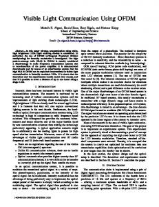
A. Link chain Fig. 1 shows the principle block diagram of the demonstrator. The link chain consists of two DSP boards, one for the transmitter (Tx) and one for receiver (Rx). In particular, the TMS320C6000 DSP evaluation board with the Texas Instruments C6713 floating-point processor, which is based on the very long instruction word (VLIW) architecture, is used. The processor runs at 250MHz. The evaluation boards contain 32-bit stereo analogue input and output ports with a maximum sampling frequency of 96kHz [13]. Matlab/Simulink is used for the development of the algorithms and the code that is run on the DSP boards.
Fig. 1.
Visible light data transmission prototype
For the purpose of demonstration, a digital image is used as the data source. The generated D/A (digital/analogue) converted OFDM signal from the sender DSP is fed to the optical transmitter circuit that drives the white LED. At the receiver, an analogue circuit with a photodiode is used to convert the optical signal to an electrical signal. The electrical signal is then passed through an A/D (analogue/digital) converter followed by cyclic prefix elimination and OFDM demodulation. These operations are preceded by a frame synchronisation routine. B. LED characteristics White LEDs are classified into two types. Some are fabricated using a blue LED chip and a phosphor. These types of LEDs have a phosphor layer on top of an InGaN-bases blue LED chip. The other types of white LEDs are fabricated by mixing light from LEDs of the three primary colours, such as red, green, and blue. All the three colours are emitted simultaneously. The optical source used in the prototype is a single chip (the first type as described above) 5mm white LED with a luminous intensity of 11000mcd. This type is chosen as it can be considered standard and inexpensive. The circuit employs a P (positive) on N (negative) silicon planar photodiode designed to deliver a maximum response
2186
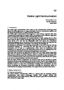
Pilots Binary-Rate Data Source
Channel Encoder
Interleaving
Assemble OFDM Symbol
Training QAMModulator
OFDM Modulator
D/A Converter
Optical Channel
Binary Data
Channel Decoder
Frequency Domain Equalisation
Deinterleaving
Training
Fig. 2.
OFDM Demodulator
Synchronisation
A/D Converter
Pilots
Visible light OFDM transmission model
through the visible part of the spectrum. The 9.8mm2 planar photodiode has a built in infrared rejection filter and provides a high shunt resistance of 0.07GOhm maximum, and low dark current of 2000pA maximum. The generated photocurrent is proportional to the incident light power and it is converted to voltage using a transimpedance configuration. The photodiode can be operated with an applied reverse bias, photoconductive mode, or unbiased, photovoltaic mode. The photodiode was chosen with the previously mentioned characteristics to achieve very low offset when the photodiode is operated in the photovoltaic mode, and when it is used in a high gain transimpedance operational amplifier circuit. For our application in the low frequency range, photovoltaic mode provides reasonable linearity and low noise.
the OFDM frame as implemented in the experimental system is formed by a time synchronisation signal (sinusoidal signal), four OFDM symbols for the training sequence, and 20 OFDM symbols with data subchannels carrying the modulated information (see Fig. 3). The channel transfer factors are obtained using the training sequence and averaging over the four training sequence periods for every subcarrier. OFDM Frame (90ms)
Synchronization Channel estimation signal training sequence
4 OFDM Symbols
Data and pilots
20 OFDM Symbols
IV. V ISIBLE L IGHT S YSTEM M ODEL The main building blocks of an OFDM-based transmitter and receiver systems are illustrated in Fig. 2. Since OFDM is based on IFFT and FFT algorithms, the implementation on the DSP is straightforward. On the OFDM Tx board, FEC coding is implemented. This is based on a rate 1/2 convolutional encoder. A time interleaver is applied. At the receiver, Viterbi decoding with hard decision output is used. In general a time varying, flat fading channel is assumed. It is further assumed that the channel remains constant within one OFDM frame. Since, however, no well established models for this particular propagation system exist, some overprovisioning in the system design is accepted. With this approach the above made assumptions are to be confirmed. For the purpose of channel estimation and synchronisation, training sequences and pilots are used [14, 15]. Concretely,
Fig. 3. OFDM frame structure: Four OFDM symbols carrying a training sequence are used for channel estimation. The data symbols are transmitted in the consecutive 20 OFDM symbols. Each of these symbols uses four subcarriers for pilot transmission.
In addition, pilots at specific subchannels are added to correct the residual channel estimation and synchronisation errors. A cyclic prefix of fixed length is added to the transmitted signal. Root raised cosine pulse shaping filters with a rolloff of 0.2 are used at the transmitter and receiver. Frequency domain equalisation is realized using conventional OFDM zero-forcing (ZF) detection. With the particular implementation the high PAR in OFDM is exploited to intensity modulate the white LED. Therefore, only real valued signals can be transmitted. This is accomplished by dividing the OFDM symbol in two halves. The
2187
second half carries the conjugate complex copy of the first half. As a consequence, after the IFFT operation, only real valued samples are obtained. These samples are fed into the root raised cosine pulse shaping filter and the resulting signal is then D/A converted. The exact structure of an OFDM symbol is depicted in Fig. 4. 0 0
0 32
D
D
1–4
D*
D*
33 – 36
P 5
P*
D
D
6–9
D*
D*
37
38 – 41
D: Complex data
P: Pilot
P 10
P* 42
D
D
11-15
D*
D*
43-47
0 16
0 48
D
D
17-21
D*
D*
49-53
P 22
P* 54
D
D
23-26
D*
D*
55-58
P 27
P* 59
D
D
28-31
D*
D*
60-63
Fig. 4. The OFDM symbols for data transmission are composed as follows (numbers in rows represent subcarrier indices): 4 pilot subchannels, 2 zeropadded subchannels to eliminate power at DC and at carrier frequency, and 26 subchannels for actual data transmission. The conjugate complex of these 32 symbols (lower part) is transmitted on another 32 subchannels in order to generate a real valued signal for the intensity modulation of the LED.
Fig. 5.
Visible light demonstrator
40
The parameters of the OFDM transmission system are listed in Table I.
35
TABLE I 30
S YSTEM MODEL SPECIFICATIONS
25
64 26 4 4 16 96kHz 0.53[A/W] 11000mcd 20 [deg.] 98mm2 60 [deg.]
SNR (dB)
Number of FFT points Number of data sub-carriers Number of pilot sub-carriers Number of guard sub-carriers Number of guard interval samples Sampling frequency The O/E conversion efficiency at a receiver luminance intensity semi angle at half power of the transmitter Detector surface area FOV at the receiver
20 15 10 5
10
20
30
Fig. 6.
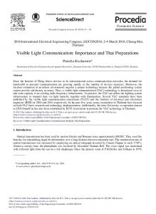
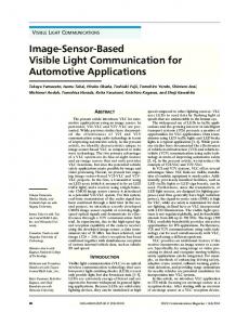
V. R ESULTS The demonstrator is depicted in Fig. 5. A single LED is used, and with the current setup a simplex link can be realised. The measurements are based on a LOS (line-of-sight) channel. As the prototype is intended for indoor data transmission applications, the measurements were taken under ambient diffused sunlight inside a room. Fig. 6 shows the SNR measured at the receiver up to one meter. In order to study the performance of the system, the modulation is changed and the performance with and without channel coding is analysed. Fig. 7 shows the BER performance versus the distance between Tx and Rx units. Measurements were taken for a distance up to 100cm. The BER of OFDM for uncoded QPSK, uncoded 16-QAM (quadrature amplitude modulation) transmission, as well as uncoded 64-QAM transmission are plotted. For the coded case, QPSK and 16-QAM results are shown. The results show that already without any channel coding, a BER of about 10−4 at a Tx-Rx separation distance of
40
50 60 70 distance (cm)
80
90
100
110
SNR measurements at the receiver
50cm can be achieved with QPSK modulation. For the same separation distance, channel coding improves the BER performance to about 10−7 . It is interesting to note, that the BER performance for coded QPSK transmission suddenly increases to 10−1 at a distance of about 1m, while the BER performance is still about 10−5 at 90cm Tx-Rx separation. This distance can hence be considered as the maximum possible distance of the single LED transmitter. A further interesting observation is that at a distance of about 20cm (20% of the maximum distance), uncoded 64QAM still results in a reasonable BER performance. In Fig. 8 the magnitude and phase of the estimated optical channel for 14 consecutive OFDM frames are shown. The 14 OFDM frames are needed to transmit one complete TIFF (Tagged Image File Format) image file. The channel is estimated for each OFDM frame. The time varying nature of the optical channel on the first 30 non-zero sub-channels of an OFDM symbol can be observed. The measurements are taken
2188
90cm with only a single LED. It is envisaged larger coverage can be obtained by using LED arrays. Moreover, the wireless channel needs to be characterised and models for it have to be developed. Furthermore, issues of optical power leakage from the transmitter to receiver will have to be addressed in order to enable full duplex communication. All this is subject to future work.
0
10
−1
10
−2
Bit Error Ratio
10
−3
10
ACKNOWLEDGEMENT
−4
10
The authors would like to thank Dr. Sinan Sinanovi´c for his helpful comments.
−5
10
16QAM uncoded 16QAM coded QPSK coded QPSK uncoded 64QAM uncoded
−6
10
R EFERENCES
−7
10
10
20
30
40
Fig. 7.
50 60 70 Distance (cm)
80
90
100
110
BER vs. Tx/Rx distances
Magnitude (V)
Channel Magnitude
4 3 2
14 12 10
8
6
4
5
2
10
Phase (rad)
Frame number
15
20
25
30
Subchannel number
5 0 −5 15
10
5
0
Frame number
0
10
20
30
Subchannel number
Fig. 8.
Optical channel estimation
at a distance of 75cm from the optical transmitter. It can be seen that the channel magnitude fluctuations in the frequency domain are insignificant. The channel can therefore be characterised as flat over the entire bandwidth. From this it can be inferred that the multipath components (if any) are closely clustered around the direct path. This behaviour is intuitively assumed due to the indoor LOS scenario. Furthermore, this particular observation can be exploited to further optimise the distribution of pilots and the channel estimation algorithms for such system.
[1] H. Park and J. Barry, “Modulation Analysis for Wireless Infrared Communications,” in Proceedings of International Conference on Communications–ICC’95, vol. 2, June,18–22 1995, pp. 1182–1186. [2] A. Moreira, A. Tavares, R. Valadas, and A. de Oliveira Duarte, “Modulation Methods for Wireless Infrared Transmission Systems - Performance Under Ambient Light Noise and Interference,” in Proceedings of SPIE Conference on Wireless Data Transmission, vol. 2601, October,23–25 1995, pp. 226–237. [3] J. Carruthers and J. Kahn, “Multiple-Subcarrier Modulation for Nondirected Wireless Infrared Communication,” IEEE Journal on Selected Areas in Communication, vol. 14, pp. 538–546, April 1996. [4] M. Audeh and J. Kahn, “Performance Evaluation of Baseband OOK for Wireless Indoor Infrared LAN’s Operation at 100 MB/s,” IEEE Transactions on Communications, vol. 43, pp. 2085–2094, June 1996. [5] J. Kahn, J. Barry, M. Audeh, J. Carruthers, W. Krause, and G. Marsh, “Non-Directed Infrared Links for High-Capacity Wireless LANs,” IEEE Personal Communication Magazine, vol. 1, pp. 12–25, 1994. [6] J. Kahn and J. Barry, “Wireless Infrared Communications,” in Proceedings of the IEEE, vol. 85, February 1997, pp. 265–298. [7] S. Nakamura, “Present Performance of InGaN-Based Blue/Green/Yellow LEDs,” in Proceedings of SPIE Conference on Light-Emitting Diodes: Research, Manufacturing, and Applications, vol. 3002, 1997, pp. 26–35. [8] T. Mukai and S. Nakamura, “White and UV LEDs,” Oyo Buturi, vol. 68, pp. 152–155, 1999. [9] H. Yaghoobi, “Scalable OFDMA Physical Layer in IEEE 802.16 WirelessMAN,” Intel Technology Journal, vol. 8, no. 3, pp. 201–212, 2004. [10] W. Zou and Y. Wu, “COFDM–An Overview,” IEEE Tranaction on Broadcasting, vol. 41, March 1995. [11] T. Komine and M. Nakagawa, “Fundamental Analysis for VisibleLight Communication System using LED Lights,” IEEE Tranaction on Consumer Electronics, vol. 50, pp. 100–107, February 2004. [12] Y. Tanaka, T. Komin, S. Haruyamaand, and M. Nakagawa, “Indoor Visible Communication Utilizing Plural White LEDs as Lighting,” in Proceedings of the 12th IEEE International Symposium on Personal, Indoor and Mobile Radio Communications (PIMRC 2001), San Diego,CA, September 2001, pp. F81–F85. [13] Texas Instruments. TMS320C6713 DSP Starter Kit. [Online]. Available: http://focus.ti.com/docs/toolsw/folders/print/tmdsdsk6713.html [14] H. Schober, F. Jondral, R. Gallacher, and Z. Wang, “Adaptive Channel Estimation for OFDM Based High Speed Mobile Communication Systems,” IEEE International Conference on Third Generation Wireless and Beyond 2001, pp. 392–397, May 2001. [15] H. Arslan and T. Ycek, “Estimation of Frequency Selectivity for OFDM Based New Generation Wireless Communication Systems,” World Wireless Congress, May 2003.
VI. C ONCLUSION A visible light wireless communication prototype was developed. The transmission is based on the assumptions of direct LOS and simplex channel conditions. It was demonstrated that the white LED based visible light data transmission system in combination with OFDM transmission is indeed technically feasible. The tests were carried out under moderate indoor ambient light conditions. It is shown that for QPSK modulation a BER of 2 × 10⁻⁵ was achieved at a distance of about
2189