814
IEEE TRANSACTIONS ON CIRCUITS AND SYSTEMS FOR VIDEO TECHNOLOGY, VOL. 17, NO. 7, JULY 2007
On-Chip Memory Optimization Scheme for VLSI Implementation of Line-Based Two-Dimentional Discrete Wavelet Transform Chih-Chi Cheng, Chao-Tsung Huang, Ching-Yeh Chen, Chung-Jr Lian, and Liang-Gee Chen, Fellow, IEEE
Abstract—The on-chip line buffer dominates the total area and power of line-based 2-D discrete wavelet transform (DWT). In this paper, a memory-efficient VLSI implementation scheme for line-based 2-D DWT is proposed, which consists of two parts, the wordlength analysis methodology and the multiple-lifting scheme. The required wordlength of on-chip memory is determined firstly by use of the proposed wordlength analysis methodology, and a memory-efficient VLSI implementation scheme for line-based 2-D DWT, named multiple-lifting scheme, is then proposed. The proposed wordlength analysis methodology can guarantee to avoid overflow of coefficients, and the average difference between predicted and experimental quality level is only 0.1 dB in terms of PSNR. The proposed multiple-lifting scheme can reduce not only at least 50% on-chip memory bandwidth but also about 50% area of line buffer in 2-D DWT module.
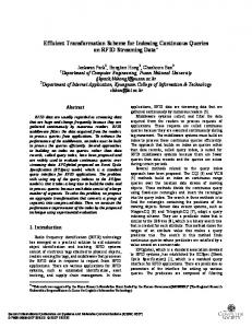
Fig. 1. General line-based scheme for single-level column-row 2-D DWT.
Index Terms—Discrete wavelet transform (DWT), image compression, JPEG 2000, MPEG-4, VLSI architecture.
I. INTRODUCTION
D
UE to many good inherent properties, 2-D discrete wavelet transform (DWT) has been regarded as an efficient tool for image and video processing [1]. Recently, 2-D DWT has been adopted as a principal coding tool of MPEG-4 still texture coding and JPEG 2000 image coding [2], [3]. Moreover, intensive research efforts have focused on the development of 3-D wavelet video coding schemes [4]. In recent years, many 2-D DWT architectures for VLSI implementation are proposed [5]–[9]. From the data in [10], external memory access is usually the component with most power consumption in a system with multimedia functionalities. According to the analysis of [5], line-based implementation can achieve minimum external memory bandwidth by use of an on-chip line buffer [11]. Therefore, line-based implementation has become one of the most commonly-used method of VLSI implementation of 2-D DWT. The definition of line-based implementation here is more general than that in [11]. The 2-D DWT implementations with nonoverlapped stripe-based scan
Manuscript received October 2, 2006; revised January 14, 2007. This work was supported in part by National Science Council, R.O.C., under Grant 95-2752-E-002-008-PAE, and in part by a MediaTek Fellowship. This paper was recommended by Associate Editor C. N. Taylor. C.-C. Cheng, C.-J. Lian, and L.-G. Chen are with the Department of Electrical Engineering, National Taiwan University, Taipei 10617, Taiwan, R.O.C. (e-mail:
[email protected];
[email protected]; lgchen@video. ee.ntu.edu.tw). C.-T. Huang is with NovaTek Microelectronics Corporation, Hsinchu City 30076, Taiwan, R.O.C. C.-Y. Chen is with MediaTek, Inc., HsinChu 30076, Taiwan, R.O.C. Digital Object Identifier 10.1109/TCSVT.2007.897106
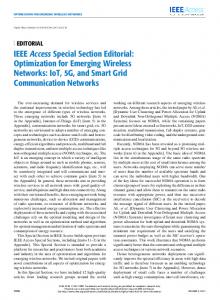
Fig. 2. Example of the temporary buffer scheme. There are four words of intrinsic register in lifting-based (9,7) filter, and the temporary buffer contains (4 Image Width) intrinsic register values.
2
and nonoverlapped block-based scan defined in [12] can also be included in the discussion here. Fig. 1 shows a general scheme for single-level line-based 2-D DWT in column-row order. The on-chip line buffer needed in line-based DWT can be decomposed into data buffer and temporary buffer as shown in Fig. 1 [6]. Data buffer is used to buffer the intermediate coefficients after column DWT. Its functionality is similar to the transpose memory for discrete cosine transform. The data buffer can be reduced into only few words of registers by use of a proper input data scan [13]. Therefore, this paper focuses on the implementation issues of temporary buffer. Fig. 2 shows the column DWT processing flow with temporary buffer. The column DWT operations are performed column-by-column with the same column DWT hardware in the right side of Fig. 2. The registers in the column DWT hardware can be decomposed into two types: intrinsic register and pipeline register. The number of intrinsic registers is determined by the adopted DWT filter coefficients and the adopted factorization scheme.
1051-8215/$25.00 © 2007 IEEE
CHENG et al.: ON-CHIP MEMORY OPTIMIZATION SCHEME
815
For example, if (9,7) filter coefficients and lifting-based factorization are adopted for column DWT hardware, the column DWT hardware can be decomposed into four stages [14] as in Fig. 2. The operation in each stage is
(1) It can be seen from (1) that one register is required to buffer the . Therefore, four registers are required value of in the column DWT hardware. These registers defined in the representations of output signals after factorization are intrinsic registers. In hardware implementation, it might be necessary to pipeline inside the column DWT hardware. Some additional registers for pipelining are thus also required. These registers are defined as pipeline registers. In Fig. 2, there are four intrinsic registers and three pipeline registers. Temporary buffer is used to buffer the intrinsic register values of every column for column DWT as illustrated in Fig. 2. The effect of pipeline registers is only to delay the output, and pipeline registers won’t effect the value of output signals. Therefore, it is not necessary to buffer the pipeline register values in the temporary buffer. The example shown in Fig. 2 is the temporal buffer of lifting-based (9,7) filter [14], [15], and there are four intrinsic register values no matter how the pipeline condition is. Therefore, the temporary buffer contains Image Width Number of Intrinsic Registers intrinsic register values. Moreover, temporary buffer has to be accessed as the way registers are accessed. Therefore, temporary buffer has to be implemented as a two-port memory. This large size and high access frequency of temporary buffer makes it the dominant factor of both area and power in a 2-D DWT module. According to the implementation results of [16], the temporary occupies more than 50% total area and power of a 2-D DWT module. In this paper, a memory-efficient implementation scheme for VLSI implementation of line-based 2-D DWT is proposed. The proposed scheme can be divided into two major parts. The first part is the analysis methodology of the wordlength in temporary buffer. This methodology can estimate the wordlength required for temporal buffer. The second part is the multiplelifting scheme which is an implementation scheme that can reduce both the memory bandwidth and the memory size of the temporary buffer. The wordlength derived using the proposed methodology can guarantee to avoid overflow of coefficients. According to the experimental results, the average difference between predicted and experimental quality level is only 0.1 dB in terms of PSNR. Moreover, about 50% area and more than 50% power of temporary buffer can be reduced by use of the proposed multiple-lifting scheme. This paper is structured as follows. The proposed wordlength analysis methodology is presented in Section II, and the proposed multiple-lifting scheme is presented in Section III. The experimental results and the corresponding discussions are shown in Section IV. Finally, Section V concludes this work.
II. TEMPORARY BUFFER WORDLENGTH ANALYSIS FOR LINE-BASED 2-D DWT There are two phenomena that make the wordlength of temporary buffer in multilevel 2-D DWT hard to be determined. The first phenomenon is the dynamic range growing effect. In multilevel DWT, the coefficients are iteratively filtered for several times. This may lead to variations in signal dynamic range. If overflow occurs, the reconstructed image quality will be severely degraded. The second phenomenon is the round-off errors. The round-off errors are induced when transforming the floating-point data into data with fixed wordlength. The errors in DWT introduce an upper bound of quality level in image/video system. To control the wordlength such that the reconstructed image can achieve the desired quality level is thus important. The overflow effect and the large round-off-error effect may be avoided by use of a large wordlength for each intrinsic register. However, this will cause a significant increase of total area and power. To use the minimum wordlength that provides the required image quality is therefore desired. Recently, there are some reports presented for wordlength designing [17], [18]. Experimental methods in [17] can not guarantee to achieve desired quality level. In [18], the round-off errors of only 1-D DWT are analyzed. Only one error source at each level is considered, and only the distortion is estimated in DWT coefficient domain rather than reconstructed image domain. Moreover, the above works do not take the dynamic range growing effects into consideration. The wordlength analysis work in [19] covers both dynamic range analysis and precision analysis. In here, a more general method that provides simplified analysis with mathematical proof and takes the wordlength fluctuations in all intrinsic registers into account. A complete analysis methodology for deriving required line-buffer wordlength in multilevel 2-D DWT is presented in this section. Not only round-off errors but dynamic range growing effects are analyzed. The proposed dynamic range analysis methodology is presented firstly. What follows is the proposed round-off error methodology. A. Proposed Dynamic Range Analysis Methodology 1) Dynamic Range Analysis of FIR Filters: Suppose a sequence with dynamic range within is fed into , the output is a FIR filter . Therefore, the maximum possible dynamic range at filter output will be . The dynamic range gain of a system is defined as the maximum possible value of (output dynamic range/input dynamic range). The dynamic range gain of this filter is (2) and the result above can also be find in [19]. Consider the case of two cascaded FIR filters and , these two filters can be merged into one equivalent FIR filter
816
IEEE TRANSACTIONS ON CIRCUITS AND SYSTEMS FOR VIDEO TECHNOLOGY, VOL. 17, NO. 7, JULY 2007
Fig. 3. Noble identity 1 applied in two-level 1-D DWT.
with coefficients total dynamic range gain of these two filters
. The is
(3) 2) LL-Band Dynamic Range Analysis: The coefficients of LL-band are analyzed because the dynamic range of coefficients th level LL band will affect the dynamic range of inof trinsic registers in th level. Fig. 3 shows the Noble identity 1 applied in two-level 1-D DWT. By applying Noble identity, the operations from signal input to each subband can be equivalent to one filter and one downsampling that will not affect the dynamic range. For example, if the low-pass filter is , the dynamic range gain is . Taking both column and row directions into consideration, the dynamic range gain of first level LL-band is thus . As for the second level LL-band, the Noble identity 1 has to be applied. The equivalent filter is , and the corresponding dynamic range gain is 1.361. Therefore, the dynamic range gain in second level LL-band is . Having the equivalent filter of LL-band at each level, the dynamic range gains of LL-band in all levels can be obtained. 3) Single Level Dynamic Range Analysis: Since DWT is a FIR filter bank, intrinsic register values can be represented as linear combinations of input signal. Therefore, the relationship from input to a given intrinsic register value can be described as an equivalent FIR filter. Take the lifting-based (9,7) filter in Fig. 4 as an example, there are four intrinsic registers values. Therefore, there are four equivalent filters for column DWT. For example, the equivalent . filter for the intrinsic register “ ” in Fig. 4 is Thus, the corresponding dynamic range gain is . All dynamic range gains from input to first-level intrinsic register values in temporary buffer can thus be obtained. 4) The Overall Infrastructure of Dynamic Range Analysis: To analyze the dynamic range gains of the intrinsic register values of all levels will be a tedious work. A tight upper bound of dynamic range gain of temporary buffer that can be derived in a much simpler way is thus proposed in this section. Lemma 1: Assume two cascaded FIR filters and have dyand , respectively. The total dynamic namic range gains is smaller than or equal to . range gain
Fig. 4. Hardware architecture of lifting-based (9,7) filter. The signals e (t) to e (t) stand for the induced round-off error sources.
Proof: From (3)
(4) Lemma 2: Let the dynamic range gain from input image to temporary buffer be , then , where is the dynamic range gain of the th intrinsic register value within single level, and is the dynamic range gain from input image to the th level LL-band. Proof: The relationship from the input to one word in intrinsic register value in th level can be taken as the cascade of th level LL-band and the the filter from input to th level LL-band to the intrinsic register filter from value in th level. Assume be the filter gain from input to the th intrinsic register value in th level column DWT. From lemma 1
(5)
CHENG et al.: ON-CHIP MEMORY OPTIMIZATION SCHEME
817
Fig. 5. Analysis flow of the proposed dynamic range analysis methodology.
The analysis flow is shown in Fig. 5. can be obtained from the LL-band dynamic range analysis described in Seccan be obtained from the single level tion II-A-2, and dynamic range analysis described in Section II-A-3. With these two values, the upper bound of the dynamic range gain can be obtained. from input image to temporary buffer Therefore, the wordlength needed to prevent overflow can be obtained.
Fig. 6. Proposed noise model for single-level DWT. (a) Model for 1-D DWT. (b) Model for 2-D DWT.
In this case, the estimated noise power derived from the assumptions in (6)
B. Proposed Round-Off Error Analysis Methodology In this section, a hierarchical model to estimate power of round-off error in reconstructed image is proposed. The derived round-off error power is a function of the number of bits in fractional part of temporary buffer. Therefore, given the desired quality level of reconstructed image, the required fractional part of wordlength in temporary buffer can be determined. 1) Model of Round-Off Operations: The most basic element in the proposed error model is the model of round-off operations. Once a round-off operation is performed, an zero-mean uniformly-distributed and temporally mutually-independent adto in Fig. 4. ditive error source is introduced, as the This assumption is also used in [19] and [20]. If there are fractional bits to represent the fractional part of a coefficient, for , the following conditions error sources are assumed:
can be
(8) Thus the noise power induced by 1-D DWT can be calculated in this way. If the input signal is with a known noise power, we assume that this error can also be modeled as a noise source that satisfies (6a) and (6b). If the filter is and the input noise power is , the noise power at filter output is induced by input noise
(6a) (6b) (6c)
2) Noise Power Model of Single-Level 1-D DWT: To analyze the noise power at 1-D DWT output, the noise sources are taken as real signals in the filter architecture. The noise power can be evaluated from the expression of noise sources. For example, and in consider the contributions of noise source Fig. 4 to the low-pass output, the round-off error expression at is low-pass output
(7)
(9) Where the is defined as the power gain of . In the proposed noise model, the input noise will be amplified by after the filtering operation. Fig. 6(a) shows the proposed noise model of single level 1-D DWT. As discussed, the fixed-point hardware will introduce , and the input noise power will round-off error power . be amplified by noise power gains
818
IEEE TRANSACTIONS ON CIRCUITS AND SYSTEMS FOR VIDEO TECHNOLOGY, VOL. 17, NO. 7, JULY 2007
Fig. 7. Proposed noise power model of multilevel 2-D DWT.
Fig. 8. Noble identity 2 applied in two-level 1-D IDWT.
3) Noise Power Model of Multi-Level 2-D DWT: Fig. 6(b) further shows the proposed noise model in single level 2-D DWT. According to our previous assumptions, we can model it as a cascade of noise models of 1-D DWT. The proposed noise model shown in Fig. 7 for multilevel 2-D DWT comprises the cascade of the single level DWT noise models. This model is also resulted from the previous assumptions. The input noise power of th level is the the LL-band th level. At the first level, the input is the noise power in original image, the input noise power is therefore zero. 4) Noise Power Analysis in Reconstructed Image: In the previous section, the noise powers in all sub-bands are calculated. To estimate the corresponding noise power in reconstructed image, noble identity 2 is utilized. As illustrated in Fig. 8, the IDWT can be considered as upsampling, filtering, and addition of each subband. Upsampling by will make the noise power . Furthermore, the equivalent filter can be modeled became as a noise power gain in the way as that in Section II-B2. For is upsampled by example, if a signal with noise power then passed to filter , the noise power at filter output is . 5) Summary of Round-Off-Error Analysis: In summary, can be obtained with the DWT noise power gains filter type. Noise power induced in 1-D DWT can be obtained by analyzing the 1-D DWT hardware architecture. The model of single level 2-D DWT can be obtained by cascading the 1-D noise models. The multilevel 2-D DWT model can be obtained by cascading the single level DWT models. By feeding zero noise power into the multilevel DWT model, the noise power of each subband can be obtained. Finally, the noise power expression in reconstructed image can be estimated by calculating the power gain of each subband using noble identity 2. This noise power expression is a function of the is number of fractional bits of data because the value of defined as in (6c). The noise power in reconstructed image is the mean-square error of pixels and can directly be mapped into peak signal-to-noise ratio (PSNR). Therefore, the required number of fractional bits in temporary buffer can be obtained from the required quality level in image domain. III. PROPOSED MULTIPLE-LIFTING SCHEME The temporary buffer access scheme is illustrated in Fig. 2 using a lifting-based (9,7) filter. In the conventional line-based DWT processing, at each clock cycle, the intrinsic register
Fig. 9. Two parallel processing scheme. The throughput is doubled by use of two sets of processing element. Therefore, the clock rate and on-chip memory access can be reduced.
values of the processed column are firstly read. After the DWT processing, the calculated intrinsic register values are written back into the temporary buffer at the same clock cycle. The next column will be processed at the next clock cycle to match the dataflow of row DWT. There are one read operation and one write operation at one clock cycle. Therefore, the temporary buffer has to be a two-port memory. Furthermore, this high access frequency makes temporary buffer to be the most power-consuming component in 2-D DWT. In this section, the multiple-lifting scheme is presented to reduce both power and area of temporary buffer. The corresponding M-scan is also proposed to reduce the overhead of multiple-lifting scheme on data buffer. A. Direct Implementation: Decrease Clock Rate by Parallel Processing One way to reduce the memory bandwidth is to use parallel processing in the way illustrated in Fig. 9. In Fig. 9, two sets of processing element (PE) are utilized. A set of PE is defined as the combinational circuits such as adders and multipliers and registers except intrinsic registers in 1-D DWT. In the architecture in Fig. 9, one operation of reading data from temporary buffer can produce two low-pass coefficients and two highpass coefficients. Because the throughput per clock cycle is doubled, the clock rate can therefore halved, and the memory access can therefore be halved. Continuing adding PEs in this way results in similar multiple-parallel processing implementation, the average memory bandwidth of temporary buffer can be arbitrarily decreased. The multiple-parallel processing implementation, however, results in increasing number of PEs. This raises the cost of DWT core. Moreover, one-read and one-write are still required within one cycle in the multiple-parallel processing implementation. The temporary buffer thus still has to be a two-port RAM. The multiple-parallel processing simply trades the increase of area for the decrease of RAM access frequency. B. Proposed
-Lifting Scheme
To overcome the side effects introduced by parallel processing implementation, the multiple-lifting scheme is proposed. The concept is to maintain the clock rate as conventional
CHENG et al.: ON-CHIP MEMORY OPTIMIZATION SCHEME
819
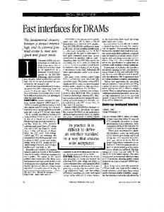
Fig. 11. Scheduling of memory access in proposed four-lifting scheme.
Fig. 10. Proposed two-lifting scheme. The operation is periodic of two clock cycles. The on-chip memory access is halved by use of four registers to buffer the intrinsic register values.
line-based implementation by folding parallel processing implementation. Therefore, only one set of PE is required and the maximum memory access within one cycle can be reduced. In the proposed -lifting scheme, the operations are periodic of clock cycles. The key idea is to consecutively process the same column for cycles and use register to buffer the intrinsic register values. At the 1st clock cycle, the intrinsic register values are read from the temporary buffer. Being different from the conventional scheme, the calculated new intrinsic register values are written to registers rather than temporary buffer. th clock cycles, the intrinsic register At the second to values are read from registers and the new intrinsic register values are written into registers. At the th clock, the intrinsic register values are read from registers and the calculated new intrinsic register values are finally written back into temporary buffer. In the conventional implementation scheme, temporary times and written for times every buffer is read for clock cycles. In the -lifting scheme, the temporary buffer is read only once and written only once every clock cycles. Take the two-parallel scheme in Fig. 9 as an example, if the signals “Output 1” and “Output 2” show up in different cycles, only one set of PE is required. To maintain the low average memory bandwidth, registers are used to buffer the calculated data along the dashed line in Fig. 9. Moreover, the reading and writing of memory can be arranged in different clock cycles such that the maximum memory access within one clock cycle is one read/write, and the temporary buffer can be a single-port RAM. The resulted two-lifting scheme is shown in Fig. 10. In even cycles, data are read from temporary buffer, and the calculated data are buffered in registers. In odd cycles, data are read from registers, and the calculated data are write into temporary buffer. The average memory bandwidth of temporary buffer is halved, and only one read or one write of temporary buffer is required per clock cycle. The proposed two-lifting scheme thus combines three advantages: halved average memory bandwidth, only one set of PE, and single-port temporary buffer. With the same design concept, the scheduling of temporary buffer in four-lifting scheme is shown in Fig. 11. The average memory bandwidth of temporary buffer in four-lifting scheme
thus can be further reduced to half of that in two-lifting scheme while still one full-utilized PE is needed. In Table I, the proposed multiple-lifting schemes are compared with the conventional line-based scheme and the parallel processing implementations in Fig. 9. The proposed multiplelifting schemes reduce the average memory bandwidth and change the temporary buffer from two-port RAM to single-port RAM while only one set of PE is needed. C. Proposed M-Scan for Multiple-Lifting Scheme The data buffer is to store the intermediate coefficients between row DWT and column DWT. As discussed, the data buffer can be reduced into only few registers by use of a Z-shaped pixel input order called Z-scan in conventional line-based implementation [13]. The proposed multiple-lifting scheme reduces the power and area of temporary buffer. To avoid overhead in data buffer, the M-scan suited for multiplelifting scheme is also proposed in this section. Fig. 12 shows the proposed M-data scan for -lifting scheme to eliminate data buffer. The main idea of this M-shape data scan is to use out the intermediate coefficients after column DWT as soon as possible. Therefore, the storage requirement of intermediate coefficients after column DWT can be minimized. As discussed in Section III-B, the scheduling of -lifting clock cycles. Assuming that 2 pixels scheme is periodic of along the column direction processed at each cycle, the length in column direction of the proposed M-data scan for -lifting scheme is thus pixels. To use out coefficients as soon as possible, the row DWT has to be performed right after the intermediate coefficients after column DWT are stored in registers. Because two pixels in row direction have to be fed in row intermediate coefficients DWT each cycle, have to be buffered. Intrinsic register values of row DWT in each rows also have to be buffered. The intrinsic register of the rows in M-scan values of the row DWT core in each of the also have to be buffered. The functionality of this additional buffer in row direction is similar to that of temporary buffer in column direction. The size of this additional buffer is four times of the number of registers in row DWT core. If lifting-based words (9,7) filter in Fig. 4 is adopted, the size of this buffer is . This small buffer can be implemented as registers with small area. As an example, the M-scan for two-lifting scheme is illustrated in Fig. 13. Because the scheduling of two-lifting scheme is periodic of two clock cycles, the length in column direction of the M-scan has to be four pixels (2 2). Therefore, eight intermediate coefficients after column DWT have to be
820
IEEE TRANSACTIONS ON CIRCUITS AND SYSTEMS FOR VIDEO TECHNOLOGY, VOL. 17, NO. 7, JULY 2007
TABLE I COMPARISONS OF TEMPORARY BUFFER IN DIFFERENT SCHEMES WITH THE SAME OUTPUT THROUGHPUT PER SECOND. B IS THE AVERAGE MEMORY BANDWIDTH (NUMBER OF MEMORY ACCESS PER SECOND) OF TEMPORARY BUFFER IN CONVENTIONAL LINE-BASED IMPLEMENTATION AS FIG. 2
temporary buffer. As can be seen in Table III, the average prediction error of the proposed precision analysis methodology is 0.12 dB, and this prediction error is within the quality variance between different input images. Therefore, the proposed methodology can provide a good reference for designing the number of fractional bits in temporary buffer. B. Results and Discussion of the Proposed Multiple-Lifting Scheme
Fig. 12. Proposed M-scan and 2-D implementation for (9,7) filter.
N -lifting scheme with
Fig. 13. Proposed M-scan and 2-D implementation for two-lifting scheme with (9,7) filter.
buffered in registers. Furthermore, the intrinsic register values of these four row also have to be buffered. If lifting-based (9,7) . filter is adopted, the size of this buffer is 16 words IV. EXPERIMENTAL RESULTS A. Results and Discussion of the Proposed Wordlength Analysis Scheme Table II shows the derived dynamic range upper bound and the experimental maximum dynamic range when random signals are taken as input. Two hardware architectures of DWT, convolutional-based [8] and lifting-based [15] architectures are implemented by Verilog HDL. As can be seen in Table II, the proposed dynamic range upper bound and the experimental maximum dynamic range yield the same number of required bits in both architectures. Therefore, the proposed upper bound of dynamic range is tight enough in designing the wordlength. Table III shows the estimated and the measured quality of reconstructed images with different number of fractional bits in
To show the efficiency of the proposed multiple-lifting scheme, three schemes are implemented using (9,7) filter with the same throughput per second. Flipping structure [21] is adopted as the 1-D DWT architecture in all three schemes. The image width is 128 pixels. The first scheme is conventional line-based lifting architecture in Fig. 4 with the nonoverlapped stripe-based scan [9], [13] of two pixels stripe width to eliminate the data buffer. The second and third schemes are the proposed two-lifting scheme and four-lifting scheme with the proposed M-scan, respectively. The comparisons of these three schemes are listed in Table IV in which TSMC 0.18- m CMOS process and Artisan 0.18- m RAM compiler are used. The area information is reported by Synopsys Design Vision and the power information is reported by Synopsys PrimePower. All three schemes are synthesized with the same timing constraint. Firstly, the total area is reduced by 28% in the proposed twolifting scheme. This reduction mainly comes from the reduction in the area of RAM. This is due to the required temporary buffer is changed from two-port RAM to single-port RAM. The area of the proposed four-lifting scheme is slightly larger than the proposed two-lifting because there are more registers needed in four-lifting scheme as discussed in Section III-C. Secondly, the total power of 2-D DWT is reduced 38% and 50% with the proposed two-lifting scheme and four-lifting scheme, respectively. The line-buffer power is reduced by 61% with two-lifting scheme because the average memory bandwidth is halved and temporary buffer becomes single-port. The line-buffer power with four-lifting scheme is reduced by 78% because the average memory bandwidth is further decreased. Because some registers have to take over the task of buffering when temporary buffer is not accessed, some power is consumed. The reduced total power is thus slightly less than the reduced power in RAM. Finally, the overhead is from the registers buffering the intermediate coefficients and data in row DWT as shown in Sec-
CHENG et al.: ON-CHIP MEMORY OPTIMIZATION SCHEME
821
TABLE II COMPARISON BETWEEN DERIVED SIGNAL UPPER BOUND OF TEMPORAL BUFFER AND THE EXPERIMENTAL MAXIMUM DYNAMIC RANGE BY INPUTTING RANDOM SIGNALS
TABLE III ESTIMATED AND MEASURED QUALITY OF RECONSTRUCTED IMAGES WITH DIFFERENT NUMBER OF FRACTIONAL BITS
TABLE IV COMPARISONS BETWEEN PROPOSED MULTIPLE-LIFTING SCHEME AND CONVENTIONAL LINE-BASED SCHEME WITH ELIMINATED DATA BUFFER UNDER THE SAME THROUGHPUT PER SECOND. ALL THREE SCHEMES HAVE THE SAME CRITICAL PATH AND OPERATE AT CLOCK FREQUENCY = 77 MHz
tion III-C. This overhead is estimated by measuring the difference between the reduction of SRAM and the total reduction. The overhead of area in two-lifting scheme in Table IV is negative because of the variance of circuit synthesis, and this also means that the area overhead can be neglected. The power in these registers is reduced greatly by using the clock gating technique. As can be seen in the discussion above, the proposed multiple-lifting scheme can reduce both total power and total area significantly. The temporary buffer size is proportional to image width, but the overhead and cores of 1-D DWT are independent of image width. The reduction ratio will be further increased with larger image size. V. CONCLUSION Line buffer dominates the area and power in line-based 2-D DWT. In this paper, a memory-efficient VLSI implementation scheme to optimize the line-buffer in 2-D DWT is proposed. The proposed scheme comprises two parts. The first part is to determine the wordlength required for line-buffer. The proposed dynamic range analysis methodology can provide a tight upper bound and guarantee to prevent the overflow in line buffer. The proposed round-off error model can predict the image-domain quality level with 0.12 dB difference, and the required fractional wordlength can be obtained from the desired quality level.
The second part is a memory efficient VLSI implementation scheme called multiple-lifting scheme. From experiment results, the proposed multiple-lifting scheme and the proposed M-scan can together reduce 28% total area and 50% total power of 2-D DWT with the same throughput. REFERENCES [1] S. G. Mallat, “A theory for multiresolution signal decomposition: The wavelet representation,” IEEE Trans. Pattern Anal. Mach. Intell., vol. 11, no. 7, pp. 674–693, Jul. 1989. [2] JPEG 2000 Image Coding System, ISO/IEC FDIS15444-1, 2000. [3] Information Technology—Coding of Audio-Visual Objects—Part 2: Visual, ISO/IEC 14496-2, 1999. [4] R. Xiong, J. Xu, F. Wu, S. Li, and Y.-Q. Zhang, “Layered motion estimation and coding for fully scalable 3-D wavelet video coding,” in Proc. Int. Conf. Image Process., 2004, pp. 2271–2274. [5] N. D. Zervas, G. P. Anagnostopoulos, V. Spiliotopoulos, Y. Andreopoulos, and C. E. Goutis, “Evaluation of design alternatives for the 2-D discrete wavelet transform,” IEEE Trans. Circuits Syst. Video Technol., vol. 1, no. 12, pp. 1246–1262, Dec. 2001. [6] P.-C. Tseng, C.-T. Huang, and L.-G. Chen, “Generic RAM-based architecture for two-dimensional discrete wavelet transform with linebased method,” in Proc. Asia-Pacific Conf. Circuits Syst., 2002, pp. 363–366. [7] C. Chakrabarti, M. Vishwanath, and R. M. Owens, “Architectures for wavelet transforms: A survey,” J. VLSI Signal Process., vol. 14, pp. 171–192, 1996. [8] K. K. Parhi and T. Nishitani, “VLSI architectures for discrete wavelet transforms,” IEEE Trans. Very Large Scale Integr. (VLSI) Syst., vol. 1, no. 2, pp. 191–202, Jun. 1993.
822
IEEE TRANSACTIONS ON CIRCUITS AND SYSTEMS FOR VIDEO TECHNOLOGY, VOL. 17, NO. 7, JULY 2007
[9] C.-T. Huang, P.-C. Tseng, and L.-G. Chen, “Memory analysis and architecture for two-dimentional discrete wavelet transform,” in IEEE Int. Conf. Acoustics, Speech, Signal Process., 2004, vol. 5, pp. 13–16. [10] T. Nishikawa et al., “A 60 MHz 240 mW MPEG-4 video-phone LSI with 16 Mb embedded DRAM,” in Dig. Tech. Papers ISSCC, 2000, pp. 230–231. [11] C. Chrysafis and A. Ortega, “Line-based, reduced memory, wavelet image compression,” IEEE Trans. Image Process., vol. 9, no. 3, pp. 378–389, Mar. 2000. [12] C.-T. Huang, P.-C. Tseng, and L.-G. Chen, “Analysis and VLSI architecture for 1-D and 2-D discrete wavelet transform,” IEEE Trans. Circuits Syst. Video Technol., vol. 53, no. 4, pp. 1575–1586, Apr. 2005. [13] M.-Y. Chiu, K.-B. Lee, and C.-W. Jen, “Optimal data transfer and buffering schemes for JPEG2000 encoder,” in Proc. IEEE Workshop Signal Process. Syst., 2003, pp. 177–182. [14] I. Daubechies and W. Sweldens, “Factoring wavelet transforms into lifting steps,” J. Fourier Anal. Appl., vol. 4, pp. 247–269, 1998. [15] W. Sweldens, “The lifting scheme: A custom-design construction of biorthogonal wavelets,” Appl. Comput. Harmonic Anal., vol. 3, no. 15, pp. 186–200, 1996. [16] C.-C. Cheng, C.-T. Huang, P.-C. Tseng, C.-H. Pan, and L.-G. Chen, “Multiple-lifting scheme: Memory-efficient VLSI implementation for line-based 2-D DWT,” in Proc. IEEE ISCAS, 2005, pp. 5190–5193. [17] M. Weeks, “Precision for 2-D discrete wavelet transform processors,” in IEEE Workshop Signal Process. Syst., 2000, pp. 80–89. [18] H. Choi, W. P. Burleson, and D. S. Phatak, “Optimal wordlength assignment for the discrete wavelet transform in VLSI,” in Proc. IEEE Workshop VLSI Signal Process., 1993, pp. 325–333. [19] D. S. Taubman and M. W. Marcellin, JPEG 2000: Image Compression Fundamentals, Standards and Practices. Norwell, MA: Kluwer, 2002. [20] K. K. Parhi, VLSI Digital Signal Processing Systems: Design and Implementation. New York: Wiley, 1999. [21] C.-T. Huang, P.-C. Tseng, and L.-G. Chen, “Flipping structure: An efficient VLSI architecture for lifting-based discrete wavelet transform,” IEEE Trans. Signal Process., vol. 52, no. 4, pp. 1080–1089, Apr. 2004.
Chih-Chi Cheng was born in Taipei, Taiwan, R.O.C., in 1982. He received the B.S. degree from the Department of Electrical Engineering, National Taiwan University, Taipei, Taiwan, R.O.C., in 2004, where he is currently pursuing the Ph.D. degree at the Graduate Institute of Electronics Engineering. His research interests include the algorithms and VLSI architectures of intelligent video signal processing and image/video coding.
Chao-Tsung Huang was born in Kaohsiung, Taiwan, R.O.C., in 1979. He received the B.S. and Ph.D. degrees in electrical engineering from National Taiwan University (NTU), Taipei, Taiwan, R.O.C., in 2001, and 2005, respectively. He joined NovaTek Microelectronics Corporation, Hsinchu City, Taiwan, R.O.C., in 2005. His major research interests include VLSI design and implementation for 1-D, 2-D, and 3-D discrete wavelet transform.
Ching-Yeh Chen was born in Taipei, Taiwan, R.O.C., in 1980. He received the B.S. and Ph.D. degrees in electrical engineering from National Taiwan University (NTU), Taipei, Taiwan, R.O.C., in 2002, and 2006, respectively. He joined MediaTek, Inc., Hsinchu, Taiwan, R.O.C., in 2006. His research interests include intelligent video signal processing, global/local motion estimation, scalable video coding, and associated VLSI architectures.
Chung-Jr Lian received the B.S., M.S., and Ph.D. degrees in electrical engineering from National Taiwan University (NTU), Taipei, Taiwan, R.O.C., in 1997, 1999, and 2003, respectively. He is now a postdoctoral research fellow at DSP/IC Design Laboratory, NTU. His major research interests include image and video coding (JPEG, JPEG 2000, MPEG, H.264/AVC), and image and video codec VLSI architecture design.
Liang-Gee Chen (S’84–M’86–SM’94–F’01) received the B.S., M.S., and Ph.D. degrees in electrical engineering from National Cheng Kung University, Tainan, Taiwan, R.O.C., in 1979, 1981, and 1986, respectively. He was an Instructor (1981–1986), and an Associate Professor (1986–1988) in the the Department of Electrical Engineering, National Cheng Kung University. In the military service during 1987 and 1988, he was an Associate Professor in the Institute of Resource Management, Defense Management College. During 1993 to 1994 he was Visiting Consultant of DSP Research Department, AT&T Bell Laboratories, Murray Hill, NJ. At 1997, he was a Visiting Scholar of the Department of Electrical Engineering, University of Washington, Seattle. In 1988, he joined the Department of Electrical Engineering, National Taiwan University, where he is currently a Professor. Since 2004, he is also the Executive Vice President and the General Director of Electronics Research and Service Organization (ERSO) in the Industrial Technology Research Institute (ITRI). His current research interests are DSP architecture design, video processor design, and video coding system. Dr. Chen has served as an Associate Editor of IEEE TRANSACTIONS ON CIRCUITS AND SYSTEMS FOR VIDEO TECHNOLOGY since 1996, as Associate Editor of the IEEE TRANSACTIONS ON VLSI SYSTEMS since 1999, as Associate Editor of IEEE TRANSACTIONS ON CIRCUITS AND SYSTEMS PART II: EXPRESS BRIEFS since 2000, and Associate Editor of the PROCEEDINGS OF THE IEEE. He has been the Associate Editor of the Journal of Circuits, Systems, and Signal Processing since 1999, and a Guest Editor for the Journal of Video Signal Processing Systems. He was the General Chairman of the 7th VLSI Design/CAD Symposium in 1995 and of the 1999 IEEE Workshop on Signal Processing Systems: Design and Implementation. He is the Past-Chair of Taipei Chapter of IEEE Circuits and Systems (CAS) Society, and is a Member of the IEEE CAS Technical Committee of VLSI Systems and Applications, the Technical Committee of Visual Signal Processing and Communications, and the IEEE Signal Processing Technical Committee of Design and Implementation of SP Systems. He is the Chair-Elect of the IEEE CAS Technical Committee on Multimedia Systems and Applications. During 2001–2002, he served as a Distinguished Lecturer of the IEEE CAS Society. He received Best Paper Awards from the R.O.C. Computer Society in 1990 and 1994. Annually from 1991 to 1999, he received Long-Term (Acer) Paper Awards. In 1992, he received the Best Paper Award of the 1992 Asia-Pacific Conference on Circuits and Systems in the VLSI design track. In 1993, he received the Annual Paper Award of the Chinese Engineers Society. In 1996 and 2000, he received the Outstanding Research Award from the National Science Council, and in 2000, the Dragon Excellence Award from Acer. He is a Member of Phi Tan Phi.