in HTML indicates a paragraph, in XML it might inform price, parameter, person, etc. depending on the context. By using regular text format, XML makes it possible for any reader to look at the text without having to use any program for that purpose, i.e, one can use any text editor to read XML file. However, XML is strict in the sense that a forgotten tag or an attribute value without quotes generates an error. XML has a set of useful modules to accomplish some tasks such as: Xlink allows to add hyperlinks to an XML file; Xpointer and Xfragments are useful in pointing to parts of an XML document; CSS is a style sheet language, just like for HTML, to apply to XML files. XSL is a language that can describe style sheets to enable to rearrange, add and delete tags and attributes; DOM allows handling XML files from a programming language; Schemas assist users to define structures of XML-based formats. The best way to appreciate and get a feeling of what XML documents look like is with a simple example - a company that sells products on-line. HTML formatting is used to describe the products; however, names and addresses of customers, and also prices and discounts are formatted with XML. A customer is described as: Acme Pharmaceuticals Co. 7301 Smokey Boulevard Smallville Indiana 94571 All the tags must have a matching end within XML syntax. As can be seen from the example, start and end tags and are used to mark up informa9
tion. Information marked by the tags is called an element; elements may be further enriched by attaching name-value pairs (for example, country=”US” in the example above) called attributes. Its syntax is quite simple syntax and can be easily processed by a machine. Moreover, it is understandable to humans. XML is based on SGML, and has a lot of similarities when compared to HTML. Detailed information about XML can be found in (Consortium, 2002c; BATES, 2003; BONNEAU et al., 2003; GRAHAM, 1999; HOLZNER, 1998; MADEN, 2000; MADEN e RAY, 2001; PINNOCK et al., 2001; ST. LAURENT, 1999; YOUNG, 2001; Iso, 2002).
10
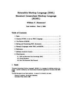
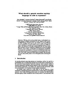
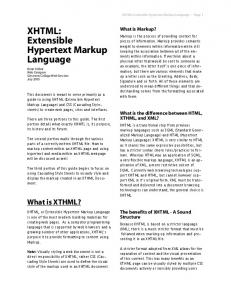
CHAPTER 4 PcML - PerformCharts Markup Language PcML is a markup language, based on XML, whose tags, attributes and other features represent the elements used in Statecharts for specifying reactive systems as well as their use in performance evaluation. A diagram of the PcML is shown in Figure 4.1.
FIGURE 4.1 – PcML Diagram. In the figure 4.1, one can notice boxes using dotted and solid lines. The former ones are not required in the specification of some systems while the latter ones are mandatory. This is because some of the elements from Statecharts are optional, such as: conditions, actions and probabilities, in contrast to the elements such as: states, events and transitions, that 11
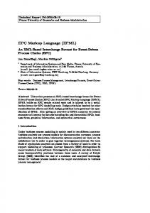
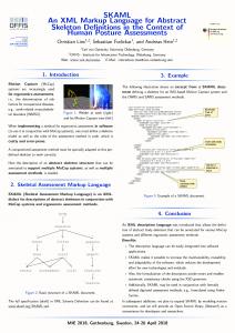
always must be used for specifying a system in Statecharts. For instance, the element description of info serves merely for documentation purposes while the element States will be used in the calls of functions in PerformCharts. The boxes connected to other boxes, with the symbol -> are the elements allowed between the matching start and end tags. Consider the element Conditions, the tags allowed between it and /Conditions are: InState, NotCondition and ComposedCondition. In the same way, the elements ANDCond and ORCond are allowed to be specified within ComposedCondition, and so on. The 1..8 means that the number of occurrences of such elements must be in the range of one to infinite. The general structure of a PcML file is shown in Figure 4.2.
12
FIGURE 4.2 – General Structure of a PcML file. XML 1.0 supplies the Document Type Definition (DTD) mechanism for declaring constraints on the use of markup, but automated processing of XML documents requires
13
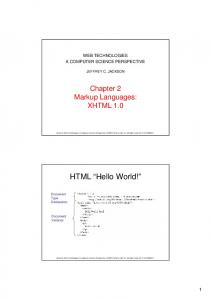
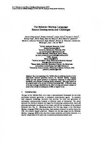
more rigorous and comprehensive facilities in this area. Requirements are for constraints on how the component parts of an application fit together, the document structure, attributes, data-typing, and so on. The XML Schema Working Group is addressing means for defining the structure, content and semantics of XML documents (Consortium, 2002a). The purpose of a schema is to define and describe a class of XML documents by using these constructs to constrain and document the meaning, usage and relationships of their constituent parts: datatypes, elements and their content, attributes and their values, entities and their contents and notations. Schema constructs may also provide for the specification of implicit information such as default values. Schemas document their own meaning, usage, and function. Thus, the XML schema language can be used to define, describe and catalogue XML vocabularies for classes of XML documents (Consortium, 2002b). For more details about the Schema for PcML, please refer to appendix A. In order to understand the specification of a reactive system within PcML consider an example of a System with two machines and a repairer shown in Figure 4.3.
FIGURE 4.3 – Specification of a system with two machines and one repairer. This system is comprised of two Machines and one Repairer. The component repairer is responsible for repairing the machines when they fail and a priority is provided to machine 1 whenever both the machines are down. The behavior of the machines and the repairer is modeled by the state transition diagram, where the basic states in both the machines are: W (Waiting), P (Processing) and B (Broken). For the repairer, the basic states are: R1 (Repairing Machine 1), WRe (Waiting) and R2 (Repairing Machine 2).
14
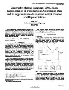
Transition 1 2 3 4 5 6 7 8 9 10 11 12
Source W1 P1 P1 B1 W2 P2 P2 B2 WRe R1 WRe R2
Event
Condition in(W2)
Action
gama1 beta1 a1 in(B1) gama2 beta2 a2 in(B1) Mi1
a1 in(B2)^not in(B1)
Mi2
a2
Destination P1 W1 B1 W1 P2 W2 B2 W2 R1 WRe R2 WRe
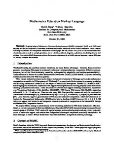
FIGURE 4.4 – Transitions of the system represented in Figure 4.3. The initial configuration of the system is obtained by taking the default basic states of each parallel component Machine 1, Machine 2 and Repairer, i.e, (P1,W2,WRe). The PcML specification of such reactive system is given in the Figure 4. Once the specification is over, a first reaction is performed by first checking the internal events. In this example the internal events are: tr[in(W2)], tr[in(B1)], tr[in(B2) ^ not in (B1)]. The initial configuration has an active state W2, so the internal event tr[in(W2)] is enabled and the configuration becomes (P1,W2,WRe). Next, the enabled events are the stochastic ones. In the list, one can notice the stochastic events: gama1 and beta1. In the case of the event gama1 were enabled, the next configuration would be (W1,W2,WRe) or, if beta1 were enabled the next configuration would be (B1,W2,WRe). Suppose that during the process of stimulating the events, a configuration is (B1,B2,WRe). In this case, the active events are the immediate events provided by tr[in(B1)] and tr[in(B2) ^ not in(B1)]. These are the events that have to be checked and enabled before the stochastic events.
15
Ana Silvia [email protected]
FIGURE 4.5 – PcML Specification of the system represented in Figure 4.3. (continue)
16
FIGURE 4.5 - (conclusion)
17
18
CHAPTER 5 On dealing with PcML for Performance Evaluation The software for PerformCharts was developed in C++. As mentioned previously, in order to compute the performance measures of a given reactive system, it is necessary to code first the specification of the system itself as a block within PerformCharts’ main program in C++. In the same main program the second part consists of generating a Markov chain and finally the third part deals with invoking the methods to determine the performance measures. The specification part within PerformCharts’ main program is basically function calls for the creation of the states, conditions, events, actions, transitions and other elements of a reactive system. The complete main program for the system represented in Figure 4.3 is shown in Figure 5.1.
19
#include #include
#include "stcht.h" #include "graphbas.h" #include "graphgen.h" #include "mkchain.h"
void main () { ofstream fout ("c:\\Statecharts\\Stcharts2\\out\\petri1.txt" ); Statechart System; // States System.createRoot("System",AND); System.createSonState ("Machine 1",OR,"System"); System.createSonState ("P1",BASIC,"Machine 1"); System.createSonState ("W1",BASIC,"Machine 1"); System.createSonState ("B1",BASIC,"Machine 1"); System.createSonState ("Machine 2",OR,"System"); System.createSonState ("P2",BASIC,"Machine 2"); System.createSonState ("W2",BASIC,"Machine 2"); System.createSonState ("B2",BASIC,"Machine 2"); System.createSonState ("Repairer",OR,"System"); System.createSonState ("WRe",BASIC,"Repairer"); System.createSonState ("R1",BASIC,"Repairer"); System.createSonState ("R2",BASIC,"Repairer"); System.setDefaultEntry ("Machine 1","P1"); System.setDefaultEntry ("Machine 2","W2"); System.setDefaultEntry ("Repairer","WRe"); // Defining Primitive Events right now for all the States. This will avoid // consistency error because when an action is declared that event // must have been defined earlier. // Primitive Events (Stochastic Events and Actions) System.createPrimEvent ("Beta1",0.1); System.createPrimEvent ("Gama1",5.0); System.createPrimEvent ("Beta2",0.2); System.createPrimEvent ("Gama2",5.0); System.createPrimEvent ("Mi1",3.0); System.createPrimEvent ("Mi2",3.0); System.createPrimEvent("a1"); System.createPrimEvent("a2");
FIGURE 5.1 – Main program in C++ for the System represented in Figure 4.3 (continue)
20
// Conditions InStateCondition *inC1 = System.createInStateCondition("W2"); InStateCondition *inC2 = System.createInStateCondition("B1"); InStateCondition *inC3 = System.createInStateCondition("B2"); NotCondition *ncC4 = System.createNotCondition(*inC2); ComposedCondition *ccC5 = System.createComposedCondition(ANDCOND,*inC3,*ncC4); // Actions EventTriggeringAction *Eta1M1 = System.createEventTrigAction("a1"); EventTriggeringAction *Eta1M2 = System.createEventTrigAction("a2"); //Events TrueCondEvent *tevE1 = System.createTrueCondEvent (*inC1); TrueCondEvent *tevE2 = System.createTrueCondEvent (*inC2); TrueCondEvent *tevE3 = System.createTrueCondEvent (*ccC5); //Probabilities // Transitions Transition *transW1_P1= System.createTransition (*tevE1); System.addSourceNode (*transW1_P1, "W1" ); System.addDestinationNode (*transW1_P1, "P1"); Transition *transP1_B1= System.createTransition ("Beta1"); System.addSourceNode (*transP1_B1, "P1" ); System.addDestinationNode (*transP1_B1, "B1"); Transition *transP1_W1= System.createTransition ("Gama1"); System.addSourceNode (*transP1_W1, "P1" ); System.addDestinationNode (*transP1_W1, "W1"); Transition *transB1_W1= System.createTransition ("a1"); System.addSourceNode (*transB1_W1, "B1" ); System.addDestinationNode (*transB1_W1, "W1"); Transition *transW2_P2= System.createTransition (*tevE2); System.addSourceNode (*transW2_P2, "W2" ); System.addDestinationNode (*transW2_P2, "P2"); Transition *transP2_B2= System.createTransition ("Beta2"); System.addSourceNode (*transP2_B2, "P2" ); System.addDestinationNode (*transP2_B2, "B2"); Transition *transP2_W2= System.createTransition ("Gama2"); System.addSourceNode (*transP2_W2, "P2" ); System.addDestinationNode (*transP2_W2, "W2"); Transition *transB2_W2= System.createTransition ("a2"); System.addSourceNode (*transB2_W2, "B2" ); System.addDestinationNode (*transB2_W2, "W2");
FIGURE 5.1 - (continuation) (continue)
21
Transition *transWRe_R1= System.createTransition (*tevE2); System.addSourceNode (*transWRe_R1, "WRe" ); System.addDestinationNode (*transWRe_R1, "R1"); Transition *transWRe_R2= System.createTransition (*tevE3); System.addSourceNode (*transWRe_R2, "WRe" ); System.addDestinationNode (*transWRe_R2, "R2"); Transition *transR1_WRe= System.createTransition ("Mi1", *Eta1M1); System.addSourceNode (*transR1_WRe, "R1" ); System.addDestinationNode (*transR1_WRe, "WRe"); Transition *transR2_WRe= System.createTransition ("Mi2", *Eta1M2); System.addSourceNode (*transR2_WRe, "R2" ); System.addDestinationNode (*transR2_WRe, "WRe"); System.printStates( fout ); System.printTransitions ( fout );
flush ( fout ); GraphBase gb; GraphGenerator gen;
//Perform reaction - generate all possible Configurations gen.generateGraph (System, gb ); gb.printOn ( fout ); flush ( fout ); //Determine steady-state probabilities MarkovChainGenerator mk ( gb ); mk.generateLimitingProbabilities ( ); mk.printLimitProbabilities ( fout ); mk.printCompStLimitProb ( fout );
}
FIGURE 5.1 - (conclusion)
22
The main idea here is to take the PcML and convert it into the main program with which one can link to other classes in order to generate the desired performance measures. As already mentioned earlier, two approaches have been used in dealing with PcML: Perl and Java. It is worth stressing that both these languages can deal with XML tags and therefore these resources have been used.
23
Schema PcMLschema.xsd Description of the PcML Elements Elements
Simple types
Actions floatProbType ANDCond floatStateType Author rootType ComposedCondition stateType Conditions Email EnteredState Events EventTriggerAction ExitedState FalseCondition History HStar Info InState Name NotCondition ORCond PcML Probabilities Probability Root State States Stochastic Transition Transitions TrueCondition
element Actions
diagram children EventTriggerAction element
used by PcML
source
Use in PcML .......
24
element ANDCond diagram element
used by ComposedCondition
Cond1 xs:string required
attributes Name Type Use Default Fixed Annotation
Cond2 xs:string required
source
PcML use
element Author
diagram
children Name Email element
used by Info
source
Use in PcML: ........
25
........
element ComposedCondition
diagram children ANDCond ORCond element
used by Conditions
Name xs:string required
attributes Name Type Use Default Fixed Annotation
source
PcML use
element Conditions
diagram
children InState NotCondition ComposedCondition element
used by PcML
source
26
Use in PcML ... The Primitive Conditions set defines, basically, the boolean values true and false to b e evaluated during a transition by the system. In addition, composed conditions also can be used in the specification of a system. The condition types implemented in the PerformCharts are: True if a component of a system is in a state specified as parameter. The opposite value of a condition specified as parameter. ..... Composed by more than one conidtion by the lo gical operator s And and OR.
element Email diagram type restriction of xs:string element
used by Author
pattern
facets [\p{L}_-]+(\.[\p{L}_-]+)*@[\p{L}_]+(\.[\p{L}_]+)+
source
element EnteredState diagram element
used by Events
Name xs:string required
attributes Name Type Use Default Fixed Annotation
source
Use in PcML
27
State xs:string required
element Events
diagram
children TrueCondition FalseCondition EnteredState ExitedState Stochastic element
used by PcML
source
element EventTriggerAction diagram element
used by Actions
Name xs:string required
attributes Name Type Use Default Fixed Annotation
source
element ExitedState diagram
28
Event xs:string required
element
used by Events
Name xs:string required
attributes Name Type Use Default Fixed Annotation
State xs:string required
source
Use in PcML
element FalseCondition diagram element
used by Events
Name xs:string required
attributes Name Type Use Default Fixed Annotation
Condition xs:string required
source
Use in PcML
element History diagram element
used by State
source
29
element HStar diagram element
used by State
source
element Info diagram
children Author Description element
used by PcML
source
Use in PcML: ... ...
element Info/Description diagram
type xs:string source
Use in PcML ...
element InState diagram element
used by Conditions
30
Name xs:string required
attributes Name Type Use Default Fixed Annotation
State xs:string required
source
Use in PcML
element Name diagram type xs:string element
used by Author
source
element NotCondition diagram element
used by Conditions
Name xs:string required
attributes Name Type Use Default Fixed Annotation
source
element ORCond diagram
31
Condition xs:string required
element
used by ComposedCondition
Cond1 xs:string required
attributes Name Type Use Default Fixed Annotation
Cond2 xs:string required
source
element PcML
diagram
children Info States Conditions Actions Events Probabilities Transitions Title xs:string required
attributes Name Type Use Default Fixed Annotation
source
32
Date xs:date
element Probabilities
diagram children Probability element
used by PcML
source
Use in PcML
element Probability diagram element
used by Probabilities
Name xs:string required
attributes Name Type Use Default Fixed Annotation
Value floatProbType required
source
Use in PcML
element Root
diagram
children State element
used by States
33
attributes Name Type Use Default Fixed Annotation
Name xs:string required
Type rootType required
source
element State
diagram
children EMPTY State History HStar elements
used by Root State
attributes Name Type Use Default Fixed Annotation
Name xs:string required
Type stateType required
source
34
Default xs:string
element State/EMPTY diagram source
element States diagram children Root element
used by PcML
source
element Stochastic diagram element
used by Events
attributes Name Type Use Default Fixed Annotation
Name xs:string required
Value floatStateType required
source
element Transition diagram used by Transitions
element
attributes Name Type Use Default Fixed Annotation
Source xs:string required
Event xs:string required
Condition xs:string
Probability xs:string
Action xs:string
Destination xs:string required
source
element Transitions
diagram children Transition element
used by PcML
source
element TrueCondition diagram element
used by Events
Name xs:string required
attributes Name Type Use Default Fixed Annotation
source
36
Condition xs:string required
simpleType floatProbType type
restriction of xs:float
used by
attribute
Probability/@Value
facets maxI nclusive
1.0 minExclusive 0.0
source
simpleType floatStateType type restriction of xs:float attribute
used by Stochastic/@Value
minExclusive
facets 0.0
source
simpleType rootType type restriction of xs:string attribute
used by Root/@Type
enumeration
facets AND
enumeration OR
source
37
simpleType stateType type used by
restriction of xs:string attribute
State/@Type
facets enu meration
BASIC enumeration XOR enumeration AND
source
38
Both the languages, Perl and Java, can deal with XML tags and these resources have been used. Both the implementations access and manipulate the PcML document by means of DOM(Document Object Model)-based parsing. This DOM parser reads an XML document and creates objects to represent the different parts of that document. These objects are associated with specific methods and properties, and are used to manipulate and access information about it. Thus, the entire XML document is represented as a hierarchy ”tree” of these objects, with the DOM parser providing a simple API to move between different branches. Once a particular node has been reached, built-in methods can be used to obtain value of the node, and use it within the script (Icarus, 2002). The DOM specification treats every part of the document as a node consisting of a type and a value. It supports all the different structures typically found in an XML document: elements, attributes, namespaces, entities, notations and others. The DOM specification is designed to be usable with any programming language. Therefore, it attempts to use a common core set of features which are available in all languages: DOM defines a standard set of interfaces for representing documents, a standard model of how these objects can be combined, and a standard set of methods for accessing and manipulating them. The DOM specification also attempts to remain neutral in its interface definitions. DOM is a W3C Recommendation and it is recognized as a Web standard. In Perl, it is implemented as a package XML::DOM. Thus, both programs read the PcML file and, according to the rules established in a DTD/Schema, check if it is well formed if the tags contained in it are valid. Errors are reported if they are found. Once the PcML specification is converted into a main program, it has to be linked to the approriate library to generate an executable file of the PerformCharts ready to be run. Perl code consists in traversing the PcML document searching for given tags with their values and attributes. Once retrieving these tags along with their corresponding values and attributes, it writes text lines in the main program file consisting of functions calls of PerformCharts. Detailed information on how to use XML in Perl, can be found in (RAY, 2002; RIEHL e STERIN, 2002) In Java, after the hierarchy tree of nodes/objects is created, the nodes will be searched by internal methods which use Xpath expressions. Detailed information on how to use XML in Java and XPath, can be found (MARUYAMA, 2002) and (VELOSO, 2003). Now, some examples of PcML definitions (for the reactive system in Figure 4.3) and their corresponding C++ commands are in order. By specifying the root and a State in PcML as the following C++ commands are generated:
39
Statechart System; System.createRoot("System",AND); System.createSonState ("Machine1",OR,"System"); System.setDefaultEntry ("Machine1","P1"); One can observe that the name assigned to the root state is also assigned to the system being modeled. The example shown above does not use any entry by History feature. In the case it were used, a command line similar to System.createHistoryEntry(”State”) would be generated. Next, the condition specification in PcML: will generate: InStateCondition *inC1 = System.createInStateCondition("W2"); Based on the appropriate definitions of the events, function calls have to be generated in the C++ program. Definition of stochastic events is based on the method createPrimEvent and its parameters are a string with the event’ s name and a transition rate. The same method is used without the transition rate for defining an event that will be used as an action. Just recalling the specification of an action for clarification purposes, in C++, action is first defined as a primitive event but without any value for the transition rate. Only then, this primitive event is defined as an action through the class EventTriggerAction. It has the same semantic meaning as pre-defined internal events (true, false, entered, exited) when considering the dynamics of Statecharts. In the case of pre-defined internal events they are also identified by names. However, some restrictions are in order: in case of true and false, if they are related to conditions, these conditions must have already been defined; when considering entered and exited, they use a state as their parameter, and the state must have already been defined. The following specification in PcML: ... ... PcML block shows a typical specification of Action. ... An example for True Condition Event is shown. Remember that the Condition C1 must 40
have been defined earlier: ... will generate the following C++ main program lines: System.createPrimEvent ("Mi1",3.0); System.createPrimEvent(a1"); EventTriggeringAction *Eta1M1 = System.createEventTrigAction("a1"); TrueCondEvent *tevE1 = System.createTrueCondEvent (*inC1); In Statecharts any event can be combined with a condition in order to guard the event meaning that even the event is enabled, it cannot be triggered if the guarding condition is not satisfied. Therefore, a class ConditionedEvent has been designed to deal with such situations and this class takes two parameters, one for the event and the second is the condition. The example shown in the Figure 4.3 has no such events. ConditionedEvent *cevR1=example.createConditionedEvent (*ncR1, ”Lambda r”); Here is one example of the creation of a transition, its specification and the C++ line command: will generate the following lines in the main program: Transition *transW1_P1 = System.createTransition (*tevE1); System.addSourceNode (*transW1_P1,"W1"); System.addDestinationNode (*transW1_P1,"P1"); Transition *transR1_WRe= System.createTransition ("Mi1", *Eta1M1); System.addSourceNode (*transR1_WRe, "R1" ); System.addDestinationNode (*transR1_WRe, "WRe" ); Finally, the following C++ program lines are the function calls that will generate the performance evaluation: GraphBase gb; GraphGenerator gen; //Perform reaction - generate all possible Configurations gen.generateGraph (System, gb ); gb.printOn ( fout ); flush ( fout ); //Determine steady-state probabilities MarkovChainGenerator mk ( gb ); 41
mk.generateLimitingProbabilities ( ); mk.printLimitProbabilities ( fout ); mk.printCompStLimitProb ( fout );
42
CHAPTER 6 Conclusions 6.1
Conclusions
Complex reactive systems are one of a kind where many intricacies have to be represented. Statecharts have powerful features where it is easier to represent such systems in most of the cases. In case of performance models, it was possible to associate Statecharts representation to a mathematical solution, in particular to Markov chains from which performance measures of a reactive system can be obtained. The question remained was the interface. A graphical interface is being developed. However, due to the growing use of interoperability technologies, especially XML, it has been decided to adopt it in the context of performance evaluation. Thus, by adapting XML to PerformCharts, PcML was created. The development of such language along with the solution approaches to deal with it were quite fast and started as a course project. This interface gave a boost to the use of PerformCharts due to its easiness in specifying a performance model. Future work related to this project is to develop a web-based PerformCharts where a reactive system can be delivered in graphical form or in PcML in order to calculate the performance measurements of the given system. The main idea is to convert the graphical interface to PcML. However, other approaches of generating the performance measurements without having to convert into a main program are under consideration.
43
44
REFERENCES 10 INTERNATIONAL ORGANIZATION STANDARDIZATION, ISO 8879:1986, Nov 2002. Standard Generalized Markup Language (SGML) http://www.iso.ch/cate/d16387.html. Bates, C. XML in theory & practice. local: [S.l.]: John Wiley Computer, 2003. 10 Bonneau, S.; Williams, k.; Tennison, J. XML design handbook. local: [S.l.]: Wrox Press LTD., 2003. 10 Consortium, W. W. W. Extensible markup language (XML) 1.0. Available in http://www.w3.org/XML/Activity, Access in Sept 2002a. 14 ——. Extensible markup language (XML) 1.0. Available in http://www.w3.org/TR/NOTE-xml-schema-req, Access in Nov 2002b.
14
——. Leading the web to its full potential... Available in http://www.w3.org, Access in Sept 2002c. 10 Drusinsky, D.; Harel, D.
Using statecharts for hardware description and synthesis. In: IEEE Transactions on Computer-Aided Design, v. 8, n. 7, p. 798–807, 1989. 5 Graham, I. XML specification guide. local: [S.l.]: John Wiley Computer, 1999. 10 Harel, D. Statecharts: a visual formalism for complex systems. Science of Computer Programming, v. 8, p. 231–274, 1987. 5, 7 Harel, D.; Lachover, H.; Naamad, A.; Pnueli, A.; Politi, M.; Sherman, R.; ShtullTrautin, A.; Trakhtenbrot, M. STATEMATE: A working environment for the development of complex reactive systems. In: IEEE Transactions on Software Engineering, v. 16, n. 4, p. 403–414, 1990. 5 Harel, D.; Naamad, A. The STATEMATE Semantics of Statecharts. ACM Transactions on Software Engineering, v. 5, n. 4, p. 293–333, 1996. 5, 7 Harel, D.; Pnueli, A.; Schmit, J.; Sherman, R. On the formal semantics of Statecharts, 1987. 5, 7 45
Harel, D.; Politi, M. Modeling reactive systems with statecharts: the statemate spproach. local: [S.l.]: McGraw-Hill, 1998. 5, 7 Holzner, S. XML Complete. local: [S.l.]: McGraw-Hill, 1998.
10
Icarus, M. Using perl with XML. Available in: http://www.devshed.com/Server_Side/Perl/PerlXML/PerlXML2/print_htm, Access in Sept 2002. DevShed.com. 39 Maden, C. Creating documents in XML. local: [S.l.]: Oreilly & Associated, 2000. 10 Maden, C.; Ray, E. Learning XML. local: [S.l.]: Oreilly & Associated, 2001.
10
Maruyama, H. XML and Java - developing web application. local: [S.l.]: Addison Wesley, 2002. 39 Philippe, B.; Saad, Y.; Stewart, W. Numerical methods in Markov chain modeling. Operations Research, v. 40, n. 6, p. 1156–1179, 1992. 5 Pinnock, J.; Dix, C.; Rafter, J. Beginning XML. Wrox Press, 2001.
10
Ray, E. T. Perl and XML. local: [S.l.]: Oreilly & Associates, Inc., 2002.
39
Riehl, M.; Sterin, I. XML and Perl. local: [S.l.]: Macmillan Computer Pub, 2002. 39 Silva, E.A.S.and Muntz, R. Computational methods to solve Markov Chains: applications to computing and communication systems, 1992. 5 ST. Laurent, S. Building XML Applications. McGraw-Hill, USA, 1999.
10
Veloso, R. R. Java e XML - guia de consulta r´apida. local: Brazil: Novatec editora, 2003. 39 Vijaykumar, N. Statecharts: Their use in specifying and dealing with Performance Models. Sao Jos´e dos Campos, Brazil. Tese – Aeronautical Institute of Technology (ITA), 1999. 5, 7 Vijaykumar, N. L.; Carvalho, S.; Abdurahiman, V. On proposing statecharts to specify performance models. International Transactions in Operational Research, v. 9, n. 3, p. 321–336, 2002. 5, 7, 8 Young, M. J. XML step by step. Local:USA: Microsoft Press., 2001. 46
10
47
APPENDIX A PcML Schema
48
49
50
51
52
INDEX C++ Program, 20–22 Conclusions, 43 PcML, 5, 7, 9, 11, 19 PCML Diagram, 11 PCML schema, 52 PcML Schema, 48 PCML schema1, 48 PCML schema2, 49 PCML schema3, 50 PCML schema4, 51 PcML Specification, 16, 17 PCML Structure, 13 System, 14 Transitions table, 15
53
INDEX C++ Program, 20–22 Conclusions, 43 PcML, 5, 7, 9, 11, 19 PCML Diagram, 11 PCML schema, 52 PcML Schema, 48 PCML schema1, 48 PCML schema2, 49 PCML schema3, 50 PCML schema4, 51 PcML Specification, 16, 17 PCML Structure, 13 System, 14 Transitions table, 15
53