Fifth IEEE Workshop on Signal Processing Advances in Wireless Communications, Lisboa, Portugal, July 11-14, 2004
On the Frequency Domain Approach for Spread Spectrum Receivers: Towards a Convergence of DS-CDMA, MC-CDMA and OFDM Cristiano Panazio
Maurice Bellanger
Conservatoire National des Arts et Mtiers (CNAM) 292, rue Saint-Martin, 75142, Paris - France - Cedex 03 Email:
[email protected]
Conservatoire National des Arts et Mtiers (CNAM) 292, rue Saint-Martin, 75142, Paris - France - Cedex 03 Email:
[email protected]
Abstract — The RAKE receiver is suboptimal when noise is non white, as in wideband CDMA systems. Frequency domain processing provides an efficient way to eliminate narrowband interference or exploit colored noise and it can significantly outperform the RAKE receiver. Additionally, other functions can be carried out directly in frequency domain, such as despreading, synchronization that is crucial for performance and equalization, which can mitigate multiuser interference. In this paper we discuss the frequency domain processing for DS-CDMA and potential gains are assessed by simulation results. An additional and important feature is that the frequency domain receiver for DS-CDMA also provides a common platform for MC-CDMA and OFDM, paving the way for an universal receiver.
I. Introduction
II. The Frequency Domain Receiver The spreading code of length N of a DS-CDMA (Direct Sequence) system can be described in the frequency domain as N carriers characterized by their amplitudes and phases. We may see this as the opposite of the generation of the time-domain signal of an MC-CDMA (Multi Carrier) system. The block-diagram of the frequency domain receiver is shown in figure 1. Cl*(0) W(0)
r(kTcN)
R(0)
X
X
Cl*(1) W(1)
r(kTcN+Tc)
R(1)
X
X
...
...
DFT ...
Spread spectrum receivers are generally implemented in the time domain: each block of received chips is correlated with the code to recover the spread data. The transmission channel is assumed flat and the major problem is the level of the noise, which is presupposed to be white and Gaussian, leading to a spreading gain equal to the length of the code. The assessment of the performance of spread spectrum is not so simple and straightforward when the transmission channel and the noise cannot be assumed flat, as in wideband CDMA (Code Division Multiple Access) systems. Non flat channel generates multiuser interference. Colored noise may arise from co-channel interference for example. Narrowband interference may be generated by means of intentional jamming, cross-modulation and intermodulation from adjacent narrowband system, harmonic distortion, interference of high clock computers and other electronic equipments. An elegant approach to introduce the dependency of the system performance on the channel frequency response and also the noise spectrum, consists in analyzing the operations of the receiver in the frequency domain. Efficient implementations of some or all the functions of spread spectrum receivers have even been proposed [1]-[6]. They are based on a DFT (Discrete Fourier Transform) whose length L equals the length N of the spreading code. References [1]-[3] exploit the fact that spreading, in fact, is a multicarrier modulation, with L carriers characterized by their amplitudes and their phases. The approach is computationally intensive, but a crucial advantage is that it provides an efficient way to eliminate narrowband interference and exploit colored noise. In addition, a global optimization of the receiver can be performed, including synchronization, equalization and optimal detection.
The purpose of the present paper is to discuss frequency domain despreading and assess the potential gains. The principle of the receiver is recalled in section 2 and its main functions are described. The impact of the noise spectrum on the performance is analyzed in section 3. Section 4 is dedicated to synchronization issues while section 5 deals with channel equalization. An important aspect of future cellular and wireless systems is raised in the conclusion, namely the compatibility of CDMA with the other major multicarrier technique, OFDM (Orthogonal Frequency Domain Multiplex). In the context of software defined radio, one can think of designing a frequency domain receiver capable of processing both types of signals.
Σ
ã (k) l
â (k) l
Cl*(N-1) W(N-1) R(N-1) X X
r(TcN(k+1)-Tc)
Figure 1: Frequency domain receiver schematics The received signals are processed by blocks of the size of the spreading code N , obtained from the continuous time function that represents the received signal r(t) given by: r(t) =
+∞ n L X X l=1 m=−∞
al
³j m k´ N
o cl (mod(m, N )) hl (t − mTc ) +n(t)
(1) where l means the l-th user, the spreading sequence is represented by cl (k), the user’s symbol is al (k) ∈ {+1, −1}, n(t) is the noise and hl (t) is the channel, which is given by:
0
hl (t) =
P X
γl,p (t)rcos (t) ∗ δ(t − τl,p )
(2)
−1
p=1
Cl∗ (i) =
N −1 X
c∗l (n)ej
2πni N
(3)
−2 Performance Degradation [dB]
where rcos (.) is the raised cosine function, δ(.) is the Dirac function, p means the p-th propagation path, τl,p and γl,p (t) are the path delay and the fading process obtained by the Jakes model respectively. Since the despreading is obtained in time domain by the code matched filter, in frequency domain the despreading is done by multiplying the DFT outputs by the conjugate of the spreading code in frequency domain, namely:
−3
−4
−5
−6
n=0 −7
The spread symbol is recovered by the following operation: a ˜(k) =
N −1 X
R(i)Cl∗ (i)
(4)
i=0
The coefficient W (i) is a complex gain that can be used to equalize the received signal and/or maximize the signal-to-noise ratio at the input of the decision device. For example, to implement the analogous of the RAKE receiver in frequency domain, we need the channel matched filter: WRAKE (i) = H ∗ (i)
0
20
30
40
50
60
Second path delay [chips]
Figure 3: Performance degradation of the frequency domain RAKE. paths synchronization, phase correction and gain ponderation
X
code correlation a*(0)
acc
X
a*(0)c*(1/z*)
a*(0)
(5)
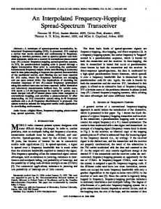
where H(i) is the N -point DFT of the channel impulse response. Such technique is used in [1]. The subscript in W denotes the criterion used to obtain the equalizer coefficient. It is worth noting that these operations in frequency would require a cyclic convolution of the channel with the transmitted signal, but this hypothesis does not hold, since the traditional DS-CDMA system does not have a cyclic prefix (CP). This leads to a segmentation of the received delayed paths, as illustrated in figure 2, leading to intersymbol interference when trying to despread them and the lost of the energy of the samples outside the DFT window. The degradation is proportional to the delay of the path and its power. In order to illustrate such performance penalty, we have simulated a DSCDMA system with a spreading factor equal to 64 over a channel h(t) = 0.707+0.707δ(t−mTc ) for various values of m. Then, we compared the performance degradation of the frequency implementation of the RAKE with the conventional one. The result is presented in figure 3.
10
z1
r(n)
X
a*(1)z1
acc
X
+
a*(1)
.. .
h*(1/z*)c*(1/z*)
c*(n)
a*(M-1) a*(M-1)zM-1 zM-1
h*(1/z*)
X
acc
X
a*(M-1)zM-1c*(1/z*)
c*(1/z*)
Figure 4: Scheme of RAKE receiver. Such filter is responsible to synchronize the paths, correct their phases and ponder their gains. Then, each path is correlated with the code and summed-up to obtain the received symbol. Since the code correlation can be done alternatively by the code matched filter, i.e., c∗ (1/z ∗ ) = c(0) + c(1)z 1 + . . . + c(N − 1)z N −1 the filter that implements the RAKE receiver is given by:
N-point DFT window
a(n-1) Delayed path
a(n) ISI
a(n+1) a(n)
Lost Energy
Figure 2: N -Point DFT window and symbol despreading. However, it is possible to overcome such problem but first, let us describe the traditional RAKE receiver. Let the channel be h(z) = a(0) + a(1)z −1 + . . . + a(M − 1)z −M +1 . The RAKE receiver is the channel-code matched filter and it is represented in figure 4. Initially, the received signal r(n) is processed by the channel matched filter: h∗ (1/z ∗ ) = a∗ (0) + a∗ (1)z 1 + · · · + a∗ (M − 1)z M −1
h∗ (1/z ∗ )c∗ (1/z ∗ )
(6)
that has M + N − 1 coefficients and that should be sampled at each N chips to obtain the estimation of the transmitted symbol. Such filtering operation can be exactly reproduced in the frequency domain if the DFT has at least N 0 = M +N −1 points, and therefore we do not get the performance degradation that exists for the N -point DFT. It is worth noting that WRAKE (i) and Cl∗ (i) must be obtained in this case by an N 0 -point DFT.
III. Noise Influence in Performance While the spreading-despreading process of the CDMA concept provides intrinsic robustness against narrowband interference and colored noise [7], the classical RAKE receiver is unable
to exploit these characteristics to increase the system performance. In order to maximize the signal-to-noise ratio, we must take into account the noise and narrowband interference power spectral density Sn , so that the matched filter (MF) is given by: (7)
20
b
o
H ∗ (i) Sn (i)
25
Ouput E /N [dB]
WM F (i) =
30
Note that, without the compensation for the noise, the matched filter is exactly the RAKE receiver. There are other receivers that can also profit of colored noise and narrowband interference. In this paper, we are going to given special attention to the LMMSE (Linear Minimum Mean Square Error) chip-level equalizer. It provides a good (iterative) solution to reduce the multiuser interference for CDMA systems that uses long codes, i.e., when the spreading sequence periodicity spans for more than a symbol period. Long codes makes impossible to use iterative solutions at symbol level to mitigate multiuser interference because the multiuser interference is no longer cyclo-stationary at symbol level. The rationale behind the LMMSE chip-level equalizer is that in downlink all users codes pass through the same channel and thus, with the equalization at chip-level, we can restitute the orthogonality of the spreading codes and eliminate multiuser interference. The LMMSE criterion in time domain is given by:
15 RAKE LMMSE Matched Filter 10
5
0
0
2
4
6
8
10
12
14
16
18
20
22
Input Eb/No [dB]
Figure 5: Colored Gaussian noise generated with a white Gaussian noise filtered with n(z) = 0.857 + 0.5145z −1 . 50
40
JLM M SE
½¯ ¯2 ¾ ¯ ¯ = E ¯s(k) − wH r(k)¯
(8)
where s(k) is the desired user spread signal and (.)H denotes conjugate and transpose. The dual in frequency-domain is given by: JLM M SE
½¯ ¯2 ¾ ¯ ¯ = E ¯Cl (i, k)a (k) − W H (i)R(i, k)¯
Ouput Eb/No [dB]
30
20 RAKE LMMSE Matched Filter 10
(9) 0
The solution for this cost function, assuming that all users transmit with the same power is :
−10
0
5
10
15
20
25
30
35
40
Input Eb/No [dB]
WLM M SE (i) =
σa2 Nu
σa2 H(i) H(i) = |H(i)|2 + σn2 Sn (i) Nu |H(i)|2 +
Sn (i) SN R
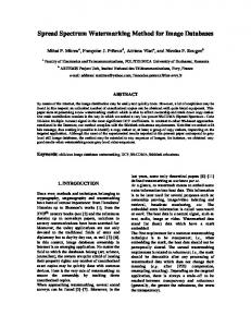
(10) where Nu is the number of active users. Comparing the LMMSE solution to the matched filter solution (7), we can see that the LMMSE solution tends to the matched filter when we have small values of SNR, i.e., when the second term of the denominator of the LMMSE solution predominates over the first one. For higher values of SNR, the LMMSE solution tends to the zero forcing solution. This equalization technique generally needs many coefficients since the delay spread usually spans several chips. Therefore, the frequency domain implementation is well-suited for minimizing the computational cost burden. In order to illustrate the performance gains for some nonwhite noise conditions, we simulate a DS-CDMA system with a 64 length Walsh-Hadamard orthogonalization code concatenated with a complex random scrambling code and h(z) = 0.727 − 0.582z −1 + 0.364z −3 . The frequency receiver was implemented with a 64-point FFT.
Figure 6: Narrowband Gaussian interference generated with a filter whose zeros are 0.8e±j0.469π and 0.8e±j0.547π and the poles are 0.99e±j0.469π and 0.99e±j0.547π . For the colored noise case in figure 5, the gain is approximately 2.2 dB and for the narrowband interference in figure 6, the gain is much more pronounced and is around 8 dB.
IV. Symbol and Chip Synchronization Synchronization is a crucial aspect of communication systems. In a frequency domain receiver implementation, the position of the DFT window must be specified, i.e., we must determine what is the timing of the CDMA spread symbol. After accomplishing this task, we must pass to chip synchronization in order to refine some misadjustment of the symbol synchronization phase and/or compensate variations of time propagation or sample frequency offsets. One way of achieving symbol synchronization is to use the correlation properties of the code. An efficient approach is to
V. Multiuser Interference Mitigation It is well known that a frequency selective channel destroys the orthogonality between the user codes. To solve this problem, many techniques have been developed [9]. The optimal receiver is far too complex for practical implementation, and thus a suboptimal, less complex, technique must be used. In this paper we focus on linear chip-level equalization techniques based on MMSE criterion. We may think of two different MMSE criterion. One has the capacity to decorrelate the users by working in the code space, taking into account the noise and users powers. It is called MMMSE linear multiuser detection in [11] and we will denote LMMSE detector (LMMSED). Its cost function is given by: n o JLM M SED = E |al (k) − wH r(k)|2 (11)
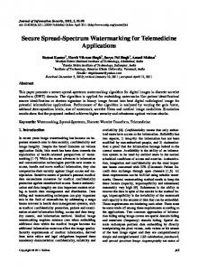
Many articles (e.g., [3][4][5]) have treated the problem of frequency domain equalization for DS-CDMA systems. However, the majority of them make use of cyclic prefix, which is unrealistic, since, currently, there is no DS-CDMA system with cyclic prefix. In this work, we do not assume cyclic prefix and the mitigation of multiuser interference is demonstrated in the following example. We assume a downlink DS-CDMA system with a 64 Walsh-Hadamard as orthogonalization code with a random complex scrambling sequence, no cyclic prefix and full load. We use the 4 path profile specified in 3GPP standard [10], with relative delay 0, Tc , 2Tc and 3Tc with the respective average power 0 dB, -3 dB, -6 dB and -9 dB. We assumed perfect knowledge of the channel. We use an extended DFT of 2N points (128) for both RAKE and LMMSE implementation to show the impact on performance of this large DFT. For the 2N -point DFT we make use of 32 chips of the previous symbol (pre-lap) and consequently, 32 chips of post-lap. 0
10
RAKE LMMSE N LMMSE 2N RAKE one user −1
10
−2
10 BER
take the inverse DFT of R(k)Cl∗ (k), which represents the correlation of the received signal with the spreading code, and search for the maximum value that represents the path with largest energy, as reference for the DFT window. Some averaging may be needed to reduce the noise and interference distortions. The estimation of chip synchronization error can be executed directly in frequency domain, for example, using a technique described in [2]. Such technique needs only the knowledge of the desired user spread code and provides performance similar to the M¨ uller and Mueller Detector [8]. For small values of rolloff (e.g., 0.22) it is similar to the performance of the traditional Early-Late Gate timing error detector [8], which is commonly used in CDMA. It is worth noting that narrowband interferers can be detected and eliminated in order to improve synchronization performance.
−3
10
−4
10
where al is the desired transmitted symbol of the l-th user, w is a Q column vector, where Q is the equalizer length and r(k) is also a Q column vector that contains the received samples. It works by calculating the cross-correlation among the users and it uses this information to eliminate multiuser interference. It is worth noting that the frequency domain equalizer is analogous to (11), where the only difference is that the vector r is replaced by its frequency domain counterpart. For synchronous users and small values of delay spread when compared to the spreading factor, a value of Q = M + N − 1 provides already good results. For the uplink system, this receiver combats the near-far problem [11]. Nevertheless, with asynchronous users, an infinite number of coefficients is needed to attain optimality. A suboptimal solution for (11) can be achieved if we use a truncated window and if we have the knowledge of all the channels and spreading codes of the active users. The same is valid for long codes systems, even synchronous one. It is noteworthy that better performance can be achieved for asynchronous chip and symbol CDMA systems by means of fractionally spaced equalizers [12]. The other technique applies to the downlink, where all active users pass through the same propagation channel. It consists in recovering the orthogonality by equalizing the received signal which is often referred to chip-level equalization. It works with short or long codes systems. It has the same performance of the linear MMSE detector for full load or one active user systems, but it has lower performance for other load conditions. We have called such technique of chip-level LMMSE and the criterion in the time domain is presented in (8) and, in the frequency domain by (9).
−5
10
0
5
10
15
20
25
Eb/No [dB]
Figure 7: Equalization Performance In this simulation, the RAKE implemented with N -point DFT matches the performance of the RAKE with 2N -point DFT for both load cases, since the channel does not have a considerable delay spread. It is worth noting that in this case the performance of the frequency RAKE implementation perfectly matches the performance of temporal RAKE. With respect to the equalization technique, the performance changes dramatically with the size of the DFT. It is seen in figure 7 that the N -point DFT implementation has an error floor, while the 2N point DFT implementation does not present such problem for the simulated Eb /No range. The error floor is mostly due to the “wrap-around” error, that can be thought of as time aliasing. The use of a 2N -point DFT can be thought of as higher “sampling rate” in frequency domain, reducing the time domain aliasing. However, the use of a larger DFT for equalization introduces also another optimization variable, that is the position of the DFT window, i.e., the amount of pre-lap and post-lap used in the equalization. We must call attention to the fact that, for CP systems, it suffices a DFT of the size of the spreading factor to attain optimal performance. Since the CP provides a circulant channel matrix, the channel can be perfectly inverted by the DFT, ex-
cept if the channel delay exceeds the CP size. An adaptive solution for the LMMSE can be easily achieved. From (10), the denominator is the power spectral density, which can be directly estimated from the output of the DFT. Such procedure avoids the problem of knowing the number of active users and the estimation of the power of the noise. The channel can be estimated recursively in time or in frequency domain, using a pilot channel or a training sequence of the desired user by means of a LMS (Least Mean Square) or even a RLS (Recursive Least Squares) algorithm. The equalizer coefficients can also be iteratively estimated in frequency domain using a LMS based on (9). The estimation of the power spectral density may be used into a normalized LMS algorithm to accelerate convergence.
VI. Discussion, Conclusion and Perspectives A terminal that can support multimode access technologies provides a more comfortable usage and it can minimize cost structure of deployed systems. In order to implement such terminal, we propose to adopt an universal receiver for DS-CDMA, MC-CDMA, OFDM and even single carrier transmission based on frequency domain processing that can fulfill these requirements and can provide an efficient receiver implementation paving the way for an universal receiver. One may ask why use DS-CDMA for future systems instead of MC-CDMA. The answer is that DS-CDMA provides a constant envelope for one user while MC-CDMA has large peak to average ratio for the envelope even for one user. Another reason is that the addition of CP complicates considerably the synchronization process and results in redundancy that may not be even exploited. Also, it is worth noting that MC-CDMA provides the same performance of long code DS-CDMA with CP and a LMMSE equalizer [4]. On the other hand, OFDM systems could be interesting if power allocation and bit loading are used. The frequency domain receiver can offer significant gain with respect to conventional time domain receivers. We have shown that we can exploit the noise characteristics and gain as much as 8 dB in comparison with the RAKE receiver. This result shows that the use of a RAKE receiver as the standard receiver for wideband CDMA may not be the best choice. Moreover, such frequency receiver can efficiently implement an equalizer to counteract multiuser access interference and near-far problems. The chip-level equalizer can be obtained by different ways, in time domain or in frequency domain, giving a good flexibility for implementation. However, each one presents different characteristics as quality of the estimated coefficients, convergence rate and computational cost that must be taken into account. For future works, a fractionally frequency implementation will also be analyzed for DS-CDMA system. Such filter can implement a matched pulse transmission filter and timing synchronization by interpolation in frequency domain, which can greatly reduce computational cost when compared to temporal implementation. It can also provide better equalization if there is excess bandwidth. Another aspect that should be analyzed is the size of pre-lap and post-lap for DFTs larger than the spreading factor, which can be a determinant performance factor.
Acknowledgments We would like to express our appreciation CAPES/COFECUB for supporting this work.
to
References [1] S. Y. Wang and C. C. Huang, “On the architecture and performance of an FFT-based spread-spectrum downlink RAKE receiver,” IEEE Transactions on Vehicular Technology, vol. 50, no. 1, pp. 234–243, January 2001. [2] C. Panazio and M. Bellanger, “Synchronisation de Symbole et de Chip dans le Domaine Frquentiel pour les Systmes DS-CDMA et MC-CDMA,” in GRETSI, Paris, France, September 2003. [3] L. Brhl and B. Rembold, “Unified Spatio-Temporal Frequency Domain Equalization for Multi- and Single-Carrier CDMA Systems,” in 56th IEEE Vehicular Technology Conference VTC’02/Fall, Vancouver, Canada, September 2002. [4] F. Adachi, T. Sao, and T. Itagaki, “Performance of multicode dscdma using frequency domain equalisation in frequency selective fading channel,” IEE Electronics Letters, vol. 39, no. 2, pp. 239– 241, January 2003. [5] I. Martoyo and F. K. Jondral, “Frequency Domain Equalization for the Downlink of CDMA Mobile Radio Systems,” in IEEE International Symposium on Advances in Wireless Communications ISWC2002, Victoria, Canada, September 2002. [6] R. Machauer, M. Iurascu and F. Jondral,“FFT speed multiuser detection for high rate data mode in UTRA-FDD,” in IEEE Vehicular Technology Conference, VTC 2001 Fall, Altantic City, US, October 2001. [7] A. Viterbi, “Spread spectrum communications: Mythes and realities,” IEEE Communications Magazine, 50th Anniversary Issue, pp. 39–41, May 2002. [8] U. Mengali and A. N. D’Andrea, Synchronization Techniques for Digital Receivers, 1st ed. New York and London : Plenun Press, 1997. [9] D. Koulakiotis and A. H. Aghvami, “Data detection techniques for DS/CDMA mobile systems: a review,” IEEE Personal Communications, vol. 7, no. 3, pp. 24–34, June 2000. [10] BS Radio transmission and Reception (FDD). 3GPP TS 25.104, V5.4.0, 2002-09. [11] S. Verd´ u, Multiuser Detection, 1st ed. Press, 1998.
Cambridge University
[12] U. Madhow and M. L. Honig, “MMSE Interference Suppresion for Direct-Sequence Spread Spectrum CDMA,” IEEE Transaction on Communications, vol. 42, no. 12, pp. 3178–3188, December 1994.