Proceeding of the IEEE 28th Canadian Conference on Electrical and Computer Engineering Halifax, Canada, May 3-6, 2015
Online Parameter Identification for a DFIG Driven Wind Turbine Generator based on Recursive Least Squares Algorithm Karim Belmokhtar, Hussein Ibrahim and Adel Merabet, Member, IEEE possibility to regulate both active and reactive power [4, 21, 22]. This paper deals with the recursive least squares (RLS) on-line parametric identification for a doubly fed induction generator (DFIG) operating in a WECS. As well as a new method for online identification of the DFIG parameter with additional noise signal is introduced. This approach permits to improve the efficiency of the fault detection systems (FDS).
Abstract— This paper describes a fault detection system strategy, which is suitable for wind generators, and may contribute to prevent failures occurring in wind energy conversion systems such as short-circuit. Indeed, the reliability of wind turbines is important in order to capture the maximum power. The proposed strategy is based on the recursive least square method for on-line identification of the generator parameters. Moreover, this approach helps to improve the model-based controller performance. The effectiveness of the proposed strategy is established through Matlab/Simulink environment.
II. ONLINE RLS PARAMETER IDENTIFICATION METHOD FOR DFIG SYSTEM
I. INTRODUCTION
N
OWADAYS, wind energy plays an important role in reducing greenhouse gas emissions [1-3]. In the last two decades, wind energy is the renewable energy source that has known the fastest growth rate in the world [4-7]. Indeed, the wind power growth rate stands at 20% annually and it is predicted that 12% of the world’s electricity may come from wind power by the year 2020 [8, 9]. On the other hand, due to the improved technology and the relative cost effective of the wind energy, it is expected that wind power is able to extract around 5% of the total world energy by the year 2020. To reach this objective, wind turbine must be more efficient, more robust and less costly than current turbines [10-13]. The fault detection and the condition monitoring have become very significant for electrical drives. Detection of sudden or developing faults which occur in actuators, or other electrical components may be economically reasonable and may participate to a safe operation and/or give a ride through capabilities for wind turbine generators (WTG) [14-18]. The reliability of the design is a significant feature for efficient and healthy operation of wind turbines. The variable-speed wind turbine has become more popular since it improves the whole amount of the extracted wind energy up to 10% and reduces mechanical stresses in comparison with the fixed-speed wind turbine [19, 20]. Wind energy conversion system (WECS) driven a doubly fed-induction generator (DFIG) is the most used system to capture the wind energy due to its many advantages such as : (1) the power converter is sized of the fully rated power, typically 16% [4], (2) reduces stress on the mechanical structure and acoustic noise and gives the
A. DFIG Modelling The mechanical power Pm captured by the turbine from the wind for a given wind speed vw is given by the following expression [4] Pm =
(1)
where ȡ is the air density in kg/m3; A=ʌR2 is the area swept by the blade in m2, and R the radius of the blade in m. The aerodynamic model of a wind turbine can be determined by the Cp(Ȝ, ȕ) curves. Cp is the power coefficient, which is a function of both tip speed ratio Ȝ and the blade pitch angle ȕ. The tip speed ratio is given by Ωr R (2) vw The mathematical expression of the power coefficient used in this paper for a wind turbine is given by [4]
λ=
§ ʌ (λ − 3) · C p = 0.398 sin ¨¨ ¸¸ − 0.00394 (λ − 2) β © 15 − 0.3β ¹
(3)
If the wind speed is below the rated value, the WTG operates in the variable speed mode, and Cp is kept at its maximum value. In this operating mode, the pitch control is deactivated. When the wind speed is above the rated value, the pitch control is activated to reduce the generated mechanical power [4, 23]. Application of Concordia and Park’s transformations to a the three-phase model of the DFIG allows writing the dynamic voltages and fluxes equations in an arbitrary (d-q) reference frame [4, 24]. °vds ° °v ° qs ® °vdr ° ° °vqr ¯
This work was supported by LTE of Hydro-Québec, H2CAN Network and the Natural Sciences and Engineering Research Council of Canada (NSERC). K. Belmokhtar and H. Ibrahim are with the TechnoCentre éolien, Gaspé, G4X 1G2 (QC), Canada (corresponding author to provide phone: +1 418 368-6162 ex 243; fax: +1 418 368-4315; e-mail:
[email protected];
[email protected]). A. Merabet is with Saint Mary’s University, Halifax, B3H 3C3 (NS), Canada (e-mail:
[email protected])
978-1-4799-5829-0/15/$31.00 ©2015 IEEE
1 ρ A C p (λ , β ) vw3 2
965
dλds − ωs λqs dt dλ = Rs iqs + qs + ωs λds dt dλdr = Rr idr + − ωr λqr dt dλqr = Rr iqr + + ωr λdr dt
= Rs ids +
(4)
where Rs and Rr are respectively the resistance of the stator and rotor windings, Ȧr and Ȧs are respectively the rotor reference frame and the rotational speed of the synchronous reference frame.
λds °λ ° qs ® °λdr °λqr ¯
excitation of the system by the input voltages. The vector ș(t) contains the parameters of the physical system to be estimated. The RLS algorithm continuously adjusts the vector y(ș,t) to imitate the response vector y(t). The online estimation process involves three steps [25]: (1) the development of a suitable model of the physical system to be identified, (2) the development of an algorithm for generating and updating the vector of the desired parameters, (3) an appropriate excitation to the physical system which allows a better convergence of the RLS algorithm. The physical model to be identified must be written in the following form
= Ls ids + M idr = Ls iqs + M iqr
(5)
= Lr idr + M ids = Ls i qs + M iqr
where Ls, and Lr are respectively the inductances of the stator and rotor windings, and M is the mutual inductance. The electromagnetic torque of the DFIG can be expressed as follow Tem = p (λds iqs − λqs ids )
(6)
Equation (9) can be re-written in matrix form as follows:
By neglecting the power losses associated with the stator resistances, the active and reactive stator power can be expressed as [4] 3 °°Ps = 2 (vds ids + vqs iqs ) ® °Q = 3 (v i − v i ) °¯ s 2 qs ds ds qs
ª y1 (t ) º ª Φ11 Φ12 « y (t ) » «Φ Φ 22 « 2 » « 21 «. » « . . « »=« . . . « » « «. » « . . « » « ¬ y n (t )¼ ¬Φ n1 Φ n 2
(7)
The mechanical equation of the DFIG is expressed as follows Tem − Tm = J e
dΩ + fe Ω dt
(9)
y (t ) = Φ T (t )θ (t )
. . . Φ1m º ªθ1 (t ) º . . . Φ 2m » «θ 2 (t ) » » »« » . . . . » «. » »« . . . . » «. » » . . . . » «. » »« . . . Φ nm ¼ ¬θ m (t )¼
(10)
with yi(t) the measured output variables (the stator and rotor voltages in the rotating synchronous d-q frame), ĭij(t) are the known functions used to describe the physical model of the system (DFIG), and și(t) represents the system parameters to be estimated, which are Rs, Rr, Ls, Lr, Je and fe. With a continuous excitation of the physical model, the parameters to be estimated must necessarily converge to the actual parameters. Indeed, it is satisfactory when the signal is sufficiently energized such that the input-output behavior can be modeled by a single parameter vector [2527]. The RLS algorithm consists on iterative calculation in order to estimate the parameters by the minimization of the quadratic error represented as follows: 2 1 n (11) e(t ) = ¦ yi (Ts ) − Φ Ti (Ts ) θ i (Ts ) 2 i =1
(8)
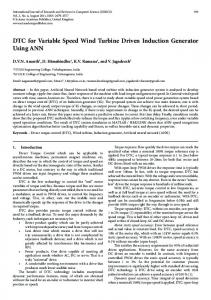
where Tm is the torque load, Je the moment of inertia, and fe is the coefficient of friction. The model of DFIG built in Matlab/Simulink is depicted in Fig. 1.
[
]
where Ts is the sampling time. Unlike a non-recursive identification techniques, the RLS algorithm is better suited for applications where detection of the rapid parameter variations over time is necessary [28]. For example, the fault which may occur in wind generator such as short-circuits can be considered as failure with rapid deterioration, which requiring a fast dynamic detection achieved with RLS algorithm. Easy hardware implementation on the numerical targets is another advantage of the RLS algorithm. In addition, RLS algorithms require little memory unlike a non-recursive algorithm. Indeed, the real time calculation principle needs less size memory [28]. The RLS algorithm with forgetting factor was chosen for its ease of implementation and its performance in terms
Fig. 1. Dynamic DFIG model of DFIG
B. RLS identification algorithm A succinct presentation of the RLS algorithm will be done since it has been widely discussed in the literature. The basic idea of the online estimation is the comparison of the observed system response y(t) to the output of a parameterized model whose structure is the same as that of the physical model [25]. In this work, the output vector y(t) represents voltages measured under conditions of 966
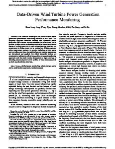
of parametric monitoring for identification of machine parameters of the DFIG. The principle of the RLS algorithm is illustrated by the block diagram in Fig. 2.
Thus, the parameters vector is calculated recursively, with the update of the adjustment gain, and can be written as follows
(
θˆk = θˆk −1 + K k y k − Φ Tk θˆk −1
)
(18)
Note that the parameter vector ș(t) must be initialized, and the initialization values do not affect the speed of convergence of the algorithm. When the values of the parameters to be identified are unknown, they can be initialized at 0. The implementation of the RLS algorithm in Matlab/Simulink is illustrated in Fig. 3. Fig. 2. Block diagram of the RLS algorithm
The equations of the RLS algorithm which can be derived from the Kalman filter equations may be expressed as follows yˆ k (t ) = Φ Tk (t ) θˆk −1 (t )
(12)
θˆk can be written as function of θˆk −1 as follows θˆk (t ) = θˆk −1 (t ) + K k ε k
(13)
with Kk is the adaptation gain which can take into account information about the value of İk which is the difference between the measured and the reconstructed model
ε k = y k − Φ Tk θˆk −1
Fig. 3. RLS algorithm implementation in Matlab/Simulink
(14) III. SIMULATION RESULTS AND DISCUSSION
The adaptation gain is written as follows [29]
In order to verify the effectiveness of the proposed online parameter identification method for the wind generator, simulations were carried out with a 7.5 kW DFIG where its parameters are given in Table I. Firstly, the DFIG identification parameter, under normal operation conditions, is given in Fig.4-6. The Fig. 4 and 5 show that the identification of the DFIG parameters has reached the actual parameters after less than two seconds. Fig. 6 illustrates the performance of the mechanical parameter identification, where the estimated values track with a good accuracy the actual values.
P Φ K k = −1 k −1T k λ + Φ k Pk −1 Φ k (15)
with Ȝ is the forgetting factor which allows taking into account the non-stationary aspect of parameters that vary over time such as DFIG's resistance and inductance. This forgetting factor can vary between 0 and 1, which permits to erase previous values during the calculation process. Thus, when Ȝ is close to 1, the previous parameters are saved, and when Ȝ is close to 0, the previous values of the parameters are cleared quickly. Pk is the matrix of observation, which can be determined by the following relationship Pk = Pk −1 −
Pk −1 Φ k ΦTk Pk −1 1 + ΦTk Pk −1 Φ k
(16)
The matrix Pk which must be reversible can be initialized as follows: ªμ 0 . . . 0 º «0 μ . . . 0» » « «. . μ . . .» Pk = μ I = « » «. . . 0 . .» «. . . . μ .» » « ¬« 0 0 . . . μ »¼
(17)
Fig.4. Rotor parameters identification
where μ >> 1, and I the identity matrix.
967
IV. CONCLUSION This paper describes a method for on-line identification of DFIG parameters in WECS with operation under parametric variations. The proposed method contributes to the improvement of the fault detection system. Future work will focus on the impact of the inertia variation on the speed controller. APPENDIX TABLE I PARAMETERS OF THE 7.5 KW DFIG
Fig. 5. Stator parameters identification
Parameter
Unit
Value
Rs Rr Ls Lr M Je fe
ȍ ȍ H H H kg·m2 Nm·s
0.45 0.62 0.084 0.081 0.078 0.3125 0.0054
REFERENCES [1] Fig. 6. Mechanical parameters identification
[2]
Then the identification algorithm is tested under variable parameters. Fig. 7 and Fig. 8 show the performance of the rotor and stator resistors under rapid variation, respectively. It can be observed that the identification method is able to track the actual value with a good performance.
[3] [4]
[5]
[6] [7]
[8] Fig. 7. Rotor resistor identification under variation [9]
[10]
[11] [12] Fig. 8. Stator resistor identification under variation [13]
968
N. Panwar, S. Kaushik, and S. Kothari, "Role of renewable energy sources in environmental protection: a review," Renewable and Sustainable Energy Reviews, vol. 15, pp. 1513-1524, 2011. R. Saidur, N. Rahim, M. Islam, and K. Solangi, "Environmental impact of wind energy," Renewable and Sustainable Energy Reviews, vol. 15, pp. 2423-2430, 2011. Y. Wang and T. Sun, "Life cycle assessment of CO2 emissions from wind power plants: Methodology and case studies," Renewable Energy, vol. 43, pp. 30-36, 2012. K. Belmokhtar, M. Doumbia, and K. Agbossou, "Novel fuzzy logic based sensorless maximum power point tracking strategy for wind turbine systems driven DFIG (doubly-fed induction generator)," Energy, 2014. E. Tremblay, S. Atayde, and A. Chandra, "Comparative study of control strategies for the doubly fed induction generator in wind energy conversion systems: a DSP-based implementation approach," Sustainable Energy, IEEE Transactions on, vol. 2, pp. 288-299, 2011. F. Dincer, "The analysis on wind energy electricity generation status, potential and policies in the world," Renewable and sustainable energy reviews, vol. 15, pp. 5135-5142, 2011. V. C. Ganti, B. Singh, S. K. Aggarwal, and T. C. Kandpal, "DFIGbased wind power conversion with grid power leveling for reduced gusts," Sustainable Energy, IEEE Transactions on, vol. 3, pp. 1220, 2012. T. R. Ayodele, A. Jimoh, J. L. Munda, and A. J. Tehile, "Challenges of Grid Integration of Wind Power on Power System Grid Integrity: A Review," International Journal of Renewable Energy Research (IJRER), vol. 2, pp. 618-626, 2012. M. A. El-Sayed, "Integrating wind energy into weak power grid using fuzzy controlled TSC compensator," in International conference on renewable energies and power quality (ICREPQ, 2010), Granada, Spain, 2010. Z. Hameed, Y. Hong, Y. Cho, S. Ahn, and C. Song, "Condition monitoring and fault detection of wind turbines and related algorithms: A review," Renewable and Sustainable energy reviews, vol. 13, pp. 1-39, 2009. K. Fung, R. Scheffler, and J. Stolpe, "Wind energy-a utility perspective," Power Apparatus and Systems, IEEE Transactions on, pp. 1176-1182, 1981. E. Sesto and C. Casale, "Exploitation of wind as an energy source to meet the world's electricity demand," Journal of Wind Engineering and Industrial Aerodynamics, vol. 74, pp. 375-387, 1998. G. Joselin Herbert, S. Iniyan, E. Sreevalsan, and S. Rajapandian, "A review of wind energy technologies," Renewable and sustainable energy Reviews, vol. 11, pp. 1117-1145, 2007.
[22] A. A. B. Mohd Zin, M. Pesaran HA, A. B. Khairuddin, L. Jahanshaloo, and O. Shariati, "An overview on doubly fed induction generatorsƍ controls and contributions to wind based electricity generation," Renewable and Sustainable Energy Reviews, vol. 27, pp. 692-708, 2013. [23] W. Qiao, W. Zhou, J. M. Aller, and R. G. Harley, "Wind speed estimation based sensorless output maximization control for a wind turbine driving a DFIG," Power Electronics, IEEE Transactions on, vol. 23, pp. 1156-1169, 2008. [24] K. Belmokhtar, M. L. Doumbia, and K. Agbossou, "Modelling and fuzzy logic control of dfig based wind energy conversion systems," in Industrial Electronics (ISIE), 2012 IEEE International Symposium on, 2012, pp. 1888-1893. [25] S. Orfanos-Pepainas, "Adaptive control and parameter identification of a doubly-fed induction generator for wind power," DTIC Document2011. [26] P. A. Ioannou and J. Sun, Robust adaptive control: Courier Dover Publications, 2012. [27] K. J. Åström and B. Wittenmark, Adaptive control: Courier Dover Publications, 2013. [28] M. Khov, "Surveillance et diagnostic des machines synchrones à aimants permanents: Détection des courts-circuits par suivi paramétrique," 2009. [29] J. C. Trigeassou, Recherche de modèles expérimentaux assistée par ordinateur: Technique et Documentation Lavoisier, 1988.
[14] J. Bekker and H. Vermeulen, "Parameter estimation of a doublyfed induction generator in a wind generation topology," in Universities Power Engineering Conference (UPEC), 2012 47th International, 2012, pp. 1-6. [15] B. Lu, Y. Li, X. Wu, and Z. Yang, "A review of recent advances in wind turbine condition monitoring and fault diagnosis," in Power Electronics and Machines in Wind Applications, 2009. PEMWA 2009. IEEE, 2009, pp. 1-7. [16] A. Kusiak and W. Li, "The prediction and diagnosis of wind turbine faults," Renewable Energy, vol. 36, pp. 16-23, 2011. [17] A. Zaher, S. McArthur, D. Infield, and Y. Patel, "Online wind turbine fault detection through automated SCADA data analysis," Wind Energy, vol. 12, pp. 574-593, 2009. [18] W. Yang, P. J. Tavner, C. J. Crabtree, and M. Wilkinson, "Costeffective condition monitoring for wind turbines," Industrial Electronics, IEEE Transactions on, vol. 57, pp. 263-271, 2010. [19] P. W. Carlin, A. S. Laxson, and E. Muljadi, "The history and state of the art of variableǦspeed wind turbine technology," Wind Energy, vol. 6, pp. 129-159, 2003. [20] S. Muller, M. Deicke, and R. W. De Doncker, "Doubly fed induction generator systems for wind turbines," Industry Applications Magazine, IEEE, vol. 8, pp. 26-33, 2002. [21] T. Burton, N. Jenkins, D. Sharpe, and E. Bossanyi, Wind energy handbook: John Wiley & Sons, 2011.
969