IEEE TRANSACTIONS ON POWER DELIVERY, VOL. 22, NO. 1, JANUARY 2007
481
Online Wavelet Transform-Based Control Strategy for UPQC Control System Mehdi Forghani and Saeed Afsharnia
Abstract—In this paper, a new algorithm is proposed to estimate amplitude and phase angle (and frequency) of load currents and source voltages in the presence of harmonics and frequency oscillation. Moreover, a comprehensive control strategy is introduced to extract the compensating signals for the control of series and shunt converters of the unified power-quality conditioner (UPQC). The basic approach used in this algorithm is to extract the fundamental component of load current and source voltage by using wavelet-transform decomposition. Then, the amplitude, phase angle, and frequency of fundamental component are calculated using the well-known LS algorithm, which is relatively simple and fast. The voltage and current references of UPQC active power filters are obtained using the positive sequence of three-phase system voltages and load currents. The proposed control strategy can extract the reference currents and voltages of UPQC fast and accurately in the presence of harmonics and/or frequency oscillation. Simulation results have been presented to show improvement of the UPQC performance in the presence of frequency and amplitude variation condition and various forms of current and voltage distortion. Index Terms—Frequency estimation, multiresolution analysis (MRA), power quality, unified power-quality conditioner (UPQC), wavelet transform.
I. INTRODUCTION
I
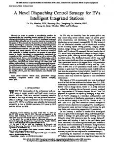
N RECENT years, active power filters (APFs) have been widely investigated for the compensation of harmonics and other distortions of power systems [1], [2]. The unified powerquality conditioner (UPQC) is one of the good custom power devices for the compensation of distortions of both source voltages and load currents. Fig. 1 shows a typical UPQC system consisting of series and shunt APFs with a common dc link [3]. The shunt APF is used to compensate for harmonic contents [4]–[6], unbalance, and reactive components [7] of the load curand to prevent the undesired effect of these distortions rent on power systems. The series APF is used for compensation of unsymmetrical and harmonic components, flicker, sag, and [6]. The common dc link of swell of the source voltage the UPQC system is comprised of two series capacitors with a grounded midpoint. The oscillation of common dc-link voltage must be compensated by shunt APF and by exchanging enough active power with the system to restore constant dc-link voltage. A big attempt is made to improve the performance of UPQC system by introducing a comprehensive control strategy to compensate for various distortions of the load currents and source Manuscript received August 18, 2004; revised May 10, 2006. Paper no. TPWRD-00384-2004. The authors are with the Department of Electrical and Computer Engineering, Tehran 14399, Iran (e-mail:
[email protected];
[email protected]. ir). Digital Object Identifier 10.1109/TPWRD.2006.883026
voltages. In this way, many control strategies have been proposed [6]–[13]. However, drawbacks of the existing methods make them ineffective in some conditions. Many of these control strategies, such as instantaneous power theory (pq-theory) [8], [9], constant source instantaneous power strategy [6], and synchronous reference frame (SRF) control strategy [6] assume that the distortion of load currents and source voltages are equal in three phases. However, in practical systems, this assumption is not correct. Moreover, available control techniques estimate changes in amplitude of load current at least one cycle after the beginning time of the change [11]. Therefore, the speed of the UPQC compensation decreases noticeably and so switching power losses increases significantly, dc-link voltage oscillation increases, and the compensator operation may become unstable. Other control strategies, such as deadbeat control strategies [12], are too complicated with limited application. Some other control strategies are based on fast Fourier transform (FFT) to extract the distortions of load currents and source voltages [13]. Although the accuracy of the response of these algorithms is acceptable in steady-state condition, they, however, estimate changes in the amplitude of the fundamental component with at least one cycle delay. Furthermore, if the power system frequency deviates from its nominal value, the control system of UPQC must be synchronized with frequency variations, usually by using another algorithm for estimating power frequency. However, most of the well-known and simple algorithms cannot quickly estimate frequency variations in the presence of harmonics. A comprehensive control strategy for UPQC system should be simple, accurate, and fast in estimating amplitude, phase angle (and frequency), and should be able to extract most of the voltage and current distortions accurately. This paper proposes a novel estimation technique and a new control strategy for the UPQC system. The proposed estimation technique is based on wavelet transform decomposition and multiresolution analysis (MRA) [14], [15], and uses the least-squares (LS) algorithm [16]–[18] to extract the fundamental component amplitude, phase angle, and frequency of load currents and source voltages. The proposed control strategy is capable of extracting most of the load current and source voltage distortions successfully. II. ESTIMATION TECHNIQUE The proposed estimation technique uses discrete wavelet transform (DWT) and MRA for extracting the fundamental component of load current and source voltage from distorted load current and source voltage. The amplitude and phase angle of the fundamental component are then obtained by using the LS algorithm.
0885-8977/$20.00 © 2007 IEEE
482
IEEE TRANSACTIONS ON POWER DELIVERY, VOL. 22, NO. 1, JANUARY 2007
Fig. 1. General configuration of UPQC.
A. Fundamental Component Extraction Wavelets have been successfully applied for signal analysis. A WT maps the time-domain signals of voltage and current in a real-valued time-frequency domain, where the signals are described by the wavelet coefficients [19]
(1)
Moreover, if the cutoff frequencies of MRA filters are selected appropriately, the sensitivity of the WT to power frequency variation is reduced. For extracting the fundamental component of a waveform by using MRA, the sampling rate of the signal and, so, the number is the lowest of MRA steps must be specified. Assume that is the number of samples in order of signal harmonics and one period of the signal. Then, the number of MRA steps can be obtained as follows: (5)
(2) (3) (4) where and are the wavelet frequency scale and wavelet time scale, respectively, and and are the wavelet coefficients. and are the mother and father wavelet functions, respectively. Similar to the fast Fourier transform (FFT) algorithm, coeffi(and ) and (and ) can be found from (3) cients and signals can be presented in terms to (6), and then of their frequency components. Equations (1) to (6) present the basic concepts of MRA. The goal of MRA is to develop reprein terms of scaling and sentations of a complicated signal wavelet functions. There is an enormous degree of freedom in the choice of wavelet basis determined by the mother wavelet. Each mother wavelet has special properties that make it suitable for special kinds of signals. In this research, we want to apply the wavelets to analyze power system harmonics which are stationary and periodic signals. Thus, a flat bandpass filter with a sharp cutoff characteristic is required. The Meyer wavelet has these properties [20], [21]. WT decomposition can be used for periodic signals as will be discussed later. Indeed, for real-time applications, the periodic signal is converted to an appropriate form to increase the accuracy of WT response. The benefit of using WT is its fast response in estimating the fundamental component of signals.
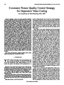
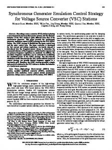
where is the number of filtering stages and is the smallest number that satisfies expression (5). If the value of expression is not selected near to , the MRA response becomes more accurate, because of the fundamental frequency (50 Hz) being far enough from division boundaries of the frequency components. This feature can be achieved by adjusting the value . of In real-time applications, using MRA for extracting fundamental component of a distorted waveform produces an extraction error shown in Fig. 2. The amount of error at the present time (0.08 s in Fig. 2) is considerable because the mother wavelet correlated with the sine waveform is not stationary and periodic. To solve the problem, the original waveform is extended by two similar periods (Fig. 3). Therefore, the present time will be far enough from the end of the synthesized signal and the extraction accuracy will increase significantly. However, if the amplitude of the original signal varies rapidly, the exact value of the fundamental component will be determined approximately one period later. To increase the speed and accuracy of signal extraction in this condition, the virtual signal for future time should be scaled as follows:
(6) is the last period of the original distorted signal and where is the virtual waveform for the future time. is the
FORGHANI AND AFSHARNIA: ONLINE WAVELET TRANSFORM-BASED CONTROL STRATEGY
483
B. Amplitude and Phase-Angle Estimation Applying MRA on the distorted signal produces a new sinusoidal waveform. In order to estimate the amplitude and phase angle (and frequency) of this waveform, the LS algorithm, which is fast and accurate for a sinusoidal waveform, is suggested. Assume that the sine wave extracted using MRA is as follows: (7)
Fig. 2. Fundamental component of a typical distorted signal.
where , , and are the amplitude, angular frequency, and . For estimating these variables using the phase angle of LS algorithm, (7) should be replaced by simple sine and cosine functions. After some mathematical manipulation, Taylor expansion of these sine and cosine functions will be as follows [16]–[18]: (8) where is the vector of last successive samples of and shown in the equation at the bottom of the page and
(9)
Fig. 3. Synthesized waveform (with 10% rise in the fundamental component amplitude after the present time).
estimated amplitude of fundamental component of original disis the mean value of the fundamental fretorted signal and quency in the last period. For each new sample of the original distorted signal, (6) should be recalculated. Small errors in estimating the amplitude of signal on future time do not affect the estimation accuracy considerably. This approach greatly increases estimation convergence. Besides, harmonic content of the virtual waveform for future time is assumed to be the same as the original waveform. Nevertheless, it will be shown that the variation of harmonic components does not affect the algorithm response noticeably.
is the frequency deviation from its initial value, where is the estimated angular frequency for the previous th sample, ( is the sampling frequency). In these and equations, is the number of original sine waveform samples , and can be found by solving (8) in use. The value of , as follows:
(10) where is the th component of and , and are estimated values of , , and . The estimated frequency will be found as (11)
484
IEEE TRANSACTIONS ON POWER DELIVERY, VOL. 22, NO. 1, JANUARY 2007
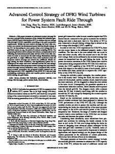
Fig. 4. Block diagram of the proposed estimation technique.
Fig. 6. Amplitude estimation error, with the FFT and the wavelet-based technique.
Fig. 5. Typical distorted load current (the amplitude increases at 0.06 s).
Fig. 4 shows the overall block diagram of the proposed waveletbased estimation technique. An advantage of this algorithm is frequency estimation without using any complicated frequency estimation technique in the presence of harmonics, because the algorithm is applied to a sine waveform without any distortion. Another advantage of the wavelet-based technique is its high speed in estimating voltage and current amplitudes especially for harmonic conditions. If the amplitude of current or voltage increases/decreases rapidly, in the worst condition, the wavelet-based technique estimates precise amplitude just a few milliseconds after the occurrence of the change while other estimation algorithms determine the precise value at least after one period (20 ms for 50 Hz). Fig. 5 shows a typical distorted load current where the amplitude of load current increases 60% at 0.06 s. Fig. 6 shows the error of the estimated amplitude obtained using the FFT algorithm and the wavelet-based technique. The wavelet-based technique acquires the exact value approximately 2.5 ms after the load current increment whereas the FFT algorithm obtains this value after 20 ms. Similar results are obtained for different amounts of amplitude increment. Fig. 7 shows a comparison between the rise time of the FFT algorithm and the wavelet-based technique responses. The time shown in this figure is the difference between the beginning of the amplitude change and the time that the estimated amplitude reaches 95% of the actual amplitude. It is shown that regardless of the amount of change in amplitude, the estimation times are approximately constant and
Fig. 7. Rising time of amplitude estimation algorithms for different amount of amplitude increment.
the estimation time of the wavelet-based technique is about nine times faster than that of the FFT algorithm. Fig. 8 shows another case that the total harmonic distortion (THD) of load current increases from 10% to 50% rapidly after 0.06 s and the amplitude of fundamental component increases from 100 A to 140 A. Fig. 9 shows the estimated amplitude using the FFT algorithm and the wavelet-based technique. It is shown that the large THD increment of the virtual waveform does not affect the estimation error of both methods noticeably. III. UPQC CONTROL SYSTEM The proposed wavelet-based estimation technique can be used for the UPQC control system to derive the fundamental component of load currents and source voltages, and then to obtain the reference current and voltage sine waveforms. The reference current and voltage sine waveforms for shunt and series active filters of UPQC should be subtracted from the original distorted waveforms to extract the distortion of the load
FORGHANI AND AFSHARNIA: ONLINE WAVELET TRANSFORM-BASED CONTROL STRATEGY
485
Fig. 8. Example of a distorted load current—THD increases from 10% to 50% together with amplitude increment. Fig. 10. Block diagram of shunt APF control strategy.
Fig. 11. Block diagram of series APF control strategy.
Fig. 9. Amplitude estimation of load current of Fig. 8.
currents and source voltages. The proposed control strategy for the UPQC control system will be discussed in Section III-A. A. Shunt APF Control Fig. 10 shows the block diagram of the proposed control strategy for the shunt APF. To compensate for active power losses of the UPQC power circuit and the active power injected to power system by the series active filter, which cause dc-link voltage reduction, some active power must be absorbed from the power system by the shunt APF. For this purpose, the dc-link voltage is compared with its reference value, and the required active current is obtained through a proportional-integrator (PI) module [6]. This current is added to the load current. The fundamental amplitude and phase angle of the total curis extracted using the proposed wavelet-based estirent mation technique discussed in the previous section. To eliminate unsymmetrical components of the three-phase load currents, the is calculated. Then, the reference sine positive sequence of source current is obtained by multiplying the amplitude of positive sequence of source currents to a sine waveform with unit amplitude and the phase angle of the fundamental component of positive-sequence load voltage. This way, reactive components
of load currents will be eliminated. If it is not required to compensate for reactive power, the phase angle of positive-sequence load current is chosen as the reference. The compensated signal will be extracted by subtracting the load currents from the reference source currents. To decrease the computing time of MRA, the number of sampling points can be reduced to about 40 points in one period (before the MRA stage in Fig. 4) using a preprocessing stage without loss of information, because the main goal of the procedure is to obtain the fundamental component of the source current. It is assumed that the distorted waveform of load cur. So rent varies linearly within a sampling time interval a curve fitting algorithm can be used to decrease the sampling rate and to constitute the reduced sampled distorted waveform. B. Series APF Control Fig. 11 shows the block diagram of the proposed control strategy for series APF. Same as the shunt APF control strategy, the phase angle and amplitude of three-phase source voltages can be estimated using the proposed wavelet-based technique. Again, for eliminating unsymmetrical components of source voltages, the positive-sequence component of the source voltages is extracted. Then, a symmetrical set of three-phase sine waveforms is produced with the reference amplitude of load voltage (power system nominal voltage) and the estimated phase angle of positive-sequence voltage. The compensated voltages are then extracted by subtracting the load voltages from these reference sine waveforms. Both shunt and series
486
IEEE TRANSACTIONS ON POWER DELIVERY, VOL. 22, NO. 1, JANUARY 2007
Fig. 12. Distribution system used for simulating UPQC operation.
TABLE I SPECIFICATIONS OF THE SHUNT AND SERIES APFS
Fig. 13. Three-phase distorted load current with variable unsymmetrical harmonic components.
APF control systems are synchronized with frequency variation of the source voltage estimated by the proposed wavelet-based algorithm. Thus, voltage sag, swell, harmonics, and flicker are also compensated. IV. SIMULATION RESULTS The proposed control strategy for the UPQC control system is simulated using MATLAB/SIMULINK software. The distribution system shown in Fig. 12 is used for evaluating UPQC operation. A nonlinear load, which produces unsymmetrical harmonic components (harmonic components that do not constitute a symmetrical system in the corresponding frequency), is connected to bus 3. An unsymmetrical load with different impedances in three phases is connected to bus 4 to produce fundamental unsymmetrical components in three-phase source voltages. The UPQC system is connected between buses 5 and 6 and in front of a nonlinear sensitive load. This sensitive nonlinear load consists of a 12-pulse thyristor rectifier and single-phase diode rectifiers (which produce unsymmetrical components in load currents) connected to phases a and c. Specifications of the power system are given in Appendix A. The UPQC system parameters are shown in Table I. The system is three-phase, four-wire and, so, zero-sequence current may flow through the fourth wire. The filter used for the dc voltage control (Fig. 10) is Butterworth of order 1 and the proportional gain of the PI controller is 80 and its integrator gain is 800. Each dc-link capacitor voltage is 500 V (Fig. 1). The output current of the shunt converter is controlled by the Hysteresis-band method and the output voltage of the series converter is controlled by the sinusoidal pulse-width modulation (SPWM) method. The passive filters connected to the output of the UPQC converters should be designed carefully. If the inductance of the series inductor of the shunt APF is chosen to be too big, undesired oscillations of the active filter current decrease, but the rate of rising filter
Fig. 14. 5th harmonic components of load currents shown in Fig. 13.
current will be limited. So a tradeoff must be made in passive filter design. Moreover, the resonance between this filter and the power system components should be avoided. Note that UPQC compensation starts at 0.04 s. A. Unsymmetrical Harmonic Compensation Fig. 13 shows three-phase unsymmetrical distorted load currents. The sensitive load in Fig. 12 includes an adjustable speed drive (ASD) with variable load. Fig. 14 shows the variation of 5th harmonic components of three-phase load currents. Fig. 15 shows the three-phase source currents compensated using the wavelet-based technique and proposed control strategy. It is observed that after 0.04 s, source currents become sinusoidal and symmetrical. Fig. 16 shows uncompensated source voltages containing unsymmetrical fundamental and harmonic components. The amplitude of source voltage is less than its nominal value. Fig. 17 shows three-phase compensated load voltages that are sinusoidal and symmetrical. The amplitude of load voltages is equal to the nominal system voltage. It can be found from Figs. 15 and 17 that compensated source currents and load
FORGHANI AND AFSHARNIA: ONLINE WAVELET TRANSFORM-BASED CONTROL STRATEGY
487
Fig. 15. Three-phase compensated source currents using the proposed control strategy.
Fig. 18. Comparison of compensated source current THDs (phase a).
Fig. 16. Three-phase distorted source voltages containing unsymmetrical harmonics and fundamental components.
Fig. 19. Comparison of compensated load voltage THDs (phase a).
Fig. 17. Three-phase compensated load voltages using the proposed control strategy.
voltages are in phase, and reactive components of load currents have been compensated. An advantage of the proposed control strategy over most of the other methods is its capability in eliminating unsymmetrical harmonic components of load currents and source voltages. Figs. 18 and 19 show the comparison between the THD of compensated source current and load voltage of phase obtained by
the wavelet-based control strategy—SRF [6] and instantaneous power control strategy ( -theory) [8], [9]. In all cases, loading conditions are similar to Figs. 13 and 16. SRF and -theory cannot extract compensating components accurately in the presence of unsymmetrical harmonics because they extract the total distortions of three-phase load currents (and source voltages) in one component. Better performance of the proposed control strategy in eliminating unsymmetrical harmonic components is evident from these figures. B. Load Change Following a change in the amplitude of load current, it is important to track the change rapidly. Any transient error in the extraction of the fundamental component of source current results in a mismatch of active power injected by shunt APF to the power system. Therefore, the voltage of dc capacitors
488
Fig. 20. Estimated amplitude of the fundamental source current (phase a).
of the UPQC deviates and the stability of UPQC operation decreases significantly or the UPQC compensation range will be limited. Moreover, active power losses of the UPQC power circuit increase and the power switches of the inverter should transfer higher current. In these conditions, a larger capacity energy storage system is required instead of dc-link capacitors to maintain stability and the operation range of the UPQC system. The main advantage of the proposed wavelet-based estimation technique is its high-speed extraction. Another simulation has been carried out to show this advantage. In this case, load current amplitudes increase approximately 50% at 0.06 s. The distortions of load currents are the same as Fig. 13. The estimated source current amplitude (fundamental amplitude of Fig. 10), obtained using the wavelet-based technique, SRF, and the FFT algorithms is shown in Fig. 20. The wavelet-based technique estimates the increased amplitude of source current much faster than the two other estimation algorithms. The FFT estimation algorithm can be used for estimating the amplitude and phase angle of voltage and current instead of the proposed wavelet-based algorithm in the proposed control strategy (Figs. 10 and 11). Figs. 21 and 22 show the compensated source currents obtained using the FFT and the waveletbased algorithms, respectively. In this case, both algorithms are used in the proposed control strategy. Both methods prove to be effective in extracting load current distortions; however, the FFT algorithm is more sluggish. Fig. 23 shows that in the case of using the FFT algorithm and SRF method, the rms value of the shunt active filter current is higher than the wavelet-based technique response. The result is higher active power losses in shunt APF and drop of dc-link voltage. Fig. 24 shows the dc-link voltage variation of the UPQC system. Greater dc-link voltage reduction (which may cause instability) in the case of using the FFT and SRF methods is due to estimation error. C. Frequency Variation Unlike the FFT algorithm, the DWT does not extract the amplitude and phase angle of a special frequency component of a
IEEE TRANSACTIONS ON POWER DELIVERY, VOL. 22, NO. 1, JANUARY 2007
Fig. 21. Compensated three-phase source currents obtained using the FFT algorithm with the proposed control strategy.
Fig. 22. Compensated three-phase source currents obtained using the waveletbased technique with the proposed control strategy.
Fig. 23. RMS value of shunt APF current (phase a).
distorted signal. For example, if the fundamental frequency of a distorted waveform is 50 Hz, DWT can extract the frequency components between 40 Hz and 60 Hz as fundamental component of the distorted waveform. Thus, if the fundamental frequency deviates from its nominal value (50 Hz), the DWT can
FORGHANI AND AFSHARNIA: ONLINE WAVELET TRANSFORM-BASED CONTROL STRATEGY
489
Fig. 26. Estimated amplitude of source current during frequency variation (phase a).
Fig. 24. DC-link voltage variation of the UPQC system.
Fig. 25. Three-phase distorted load current with varying frequency.
still extract the fundamental component of the distorted waveform. Moreover, the LS algorithm, which is applied to the sine waveform obtained with the aid of MRA for estimating its amplitude and phase angle, can extract the fundamental frequency rapidly. Therefore, the proposed estimation algorithm synchronizing with frequency drifts rapidly. These benefits render the wavelet-based technique to be less sensitive to frequency oscillation. In contrast, other amplitude and phase-angle estimation algorithms must be synchronized with frequency variation using other frequency estimation algorithms [22], which are not as fast and simple as the LS algorithm in harmonic conditions. Therefore, they are more time consuming and complicated in harmonic conditions. Fig. 25 shows three-phase load currents of the system shown in Fig. 12. In this case, the frequency of source voltages increases uniformly after 0.06 s as follows: (12) Fig. 26 shows the amplitude of the source current extracted by the wavelet-based technique and the FFT algorithm. The discrete Fourier transform (DFT) is used to synchronize the FFT with frequency variation [23]. There is no considerable difference between estimated amplitudes obtained by both algorithms
between 0.06 s and approximately 0.09 s, because the frequency deviation from its nominal value is not considerable. After that, a greater difference is observed between the two estimated current amplitudes. This is due to error in estimating the fundamental frequency by the DFT algorithm. As a result of this error, as the frequency of source voltages increases, the FFT algorithm control strategy yields load voltages (and source current) with 50-Hz frequency. Therefore, more active power than needed is exchanged with the power system by the series active filter and so active current absorbed for the compensating dc voltage reduction increases. The waveform of the compensated source currents and load voltages obtained using the FFT and the wavelet-based algorithms are comparatively the same because they use the proposed control strategy in both cases. This is the advantage of the proposed control strategy that if the estimated frequency, amplitude, and phase angle have some error, the compensated source currents and load voltages are still sinusoidal and symmetrical. The major difference is in the amount of active power losses and stability of UPQC compensation. Fig. 27 shows the frequency estimation obtained by the LS (with the wavelet-based algorithm) and DFT algorithms. The LS algorithm estimates frequency more accurately and faster than DFT algorithm. Figs. 28 and 29 show rms values of shunt and series APF current and voltage, respectively. In both figures, the rms values obtained using the FFT algorithm are greater than using the wavelet-based technique after approximately 0.09 s. is the active filter current component that compensates for load current distortion and is the dc-link voltage reduction compensating component. The values of and in both cases do not differ considerably before approximately 0.09 s. After this time and in the case of using the FFT algorithm, greater injected voltage and current to the power system causes more dc-link voltage reduction and so, more active current and active power will be absorbed from the power system. V. CONCLUSION This paper expands the application of the DWT and MRA for extracting the fundamental component of load current and
490
Fig. 27. Estimated power frequency using LS and DFT.
IEEE TRANSACTIONS ON POWER DELIVERY, VOL. 22, NO. 1, JANUARY 2007
source current and source voltage is obtained by MRA, and then the LS algorithm is applied to extract its amplitude, phase angle, and frequency. It is shown that the proposed technique is capable of estimating the amplitude and phase angle of a distorted waveform fast and accurately. Moreover, a new comprehensive control strategy has been proposed to extract the current and voltage references of shunt and series active filters, respectively. The proposed control strategy compensates for unsymmetrical harmonic components as well as most of the other distortions. Simulation results show that unlike SRF and -theory algorithms, the proposed control strategy can compensate for unsymmetrical harmonic contents of load currents and source voltages. Another advantage of the proposed control technique is its fast response to the changes in load current amplitude. As shown in the results, the proposed control strategy provides better dynamic responses to load current variation than the FFT algorithm and SRF control strategy, and so the stability of UPQC control is enhanced. Further, the proposed control technique is not sensitive to power frequency variation, because the LS technique can estimate the power frequency faster than other well-known and simple frequency estimation techniques such as DFT in the presence of harmonics. APPENDIX Power network
Fig. 28. RMS value of shunt APF current (phase a).
, . Power transformer: 500 kVA, 20/0.38 kV, . , Line impedances , . Load impedance Unsymmetrical load impedances , .
, , , . ,
REFERENCES
Fig. 29. RMS value of series APF voltage (phase a).
source voltage of the power system to obtain current and voltage references for compensating for the distortion of these waveforms by the UPQC system. The fundamental component of
[1] H. Fujita and H. Akagi, “The unified power quality conditioner: The integration of series and shunt active filter,” IEEE Trans. Power Electron., vol. 13, no. 2, pp. 315–322, Mar. 1998. [2] F. Kamron, “Combined deadbeat control of series-parallel converter combination used as a universal power filter,” in Proc. IEEE Power Electronics Specialists Conf., 1995, pp. 196–201. [3] M. Aredes, K. Heumann, and E. H. Watanabe, “An universal active power line conditioner,” IEEE Trans. Power Del., vol. 13, no. 2, pp. 545–551, Apr. 1998. [4] L. M. Tolbert and P. Z. Peng, “A multilevel converter based universal power conditioner,” IEEE Trans. Ind. Appl., vol. 36, no. 2, pp. 596–603, Mar./Apr. 2000. [5] D. Nedeljkovic, J. Nastaran, and D. Voncina, “Synchronizing of active power filter current reference to the network,” IEEE Trans. Ind. Electron., vol. 46, no. 2, pp. 333–339, Apr. 1999. [6] M. Aredes and E. H. Watanabe, “Three-phase four-wire shunt active filter control strategies,” IEEE Trans. Power Electron., vol. 12, no. 2, pp. 311–318, Mar. 1997. [7] J. W. Dixon, G. Venegas, and L. A. Moran, “A series active filter based on a sinusoidal current-controlled voltage-source inverter,” IEEE Trans. Ind. Electron., vol. 44, no. 5, pp. 612–620, Oct. 1998. [8] J. S. Hsul, “Instantaneous phasor method for obtaining instantaneous balanced fundamental components for power quality control and continuous diagnostics,” IEEE Trans. Power Del., vol. 13, no. 4, pp. 1494–1500, Oct. 1998. [9] H. Akagi et al., “Instantaneous reactive power compensator comprising switching devices without energy storage components,” IEEE Trans. Ind. Appl., vol. IA-20, no. 3, pp. 625–630, May/Jun. 1984.
FORGHANI AND AFSHARNIA: ONLINE WAVELET TRANSFORM-BASED CONTROL STRATEGY
[10] M. T. Haque, T. Ise, and S. H. Hosseini, “A novel control strategy for unified power quality conditioner (UPQC),” in Proc. Power Electronics Specialists Conf., Jun. 23–27, 2002, vol. 1, PESC 02. 2002 IEEE 33rd Annual. [11] D. Graovac and V. Kati, “On-line control of current source type active rectifier using transfer function approach,” IEEE Trans. Ind. Electron., vol. 48, no. 3, pp. 526–535, Jun. 2001. [12] K. Gokhale, A. Kawamura, and R. Hoft, “Deadbeat microprocessor control of PWM inverter for sinusoidal output waveform synthesis,” IEEE Trans. Ind. Appl., vol. IA-23, no. 5, pp. 901–910, Sep./Oct. 1987. [13] A. A. Girgis and F. Ham, “A quantitative study of pitfall in FFT,” IEEE Trans. Electron. Syst., vol. ES-16, no. 4, pp. 434–439, Jul. 1980. [14] C. S. Burrus, R. A. Gopinath, and H. Guo, Introduction to Wavelets and Wavelet Transform. Upper Saddle River, NJ: Prentice-Hall, 1998, . [15] S. G. Mallat, “A theory for multiresolution signal decomposition: The wavelet representation,” IEEE Trans. Pattern Anal. Mach. Intell., vol. 11, no. 7, pp. 674–693, Jul. 1989. [16] I. Kamwa and R. Grondin, “Fast adaptive schemes for tracking voltage phasor and local frequency in power transmission and distribution technique,” IEEE Trans. Power Del., vol. 7, no. 2, pp. 789–795, Apr. 1992. [17] M. S. Sachdev and M. M. Giray, “A least square technique for determining power system frequency,” IEEE Trans. Power App. Syst., vol. PAS-104, no. 2, pp. 437–443, Feb. 1985. [18] I. Kamwa and R. Grondin, “Fast adaptive schemes for tracking voltage phasor and local frequency in power transmission and distribution systems,” IEEE Trans. Power Del., vol. 7, no. 2, pp. 789–795, Apr. 1992. [19] W. K. Yoon and M. J. Devaney, “Power measurement using the wavelet transform,” IEEE Trans. Instrum. Meas., vol. 47, no. 5, pp. 1205–1210, Oct. 1998. [20] J. Driesen, T. Van Craenenbroek, R. Reekmans, and D. Van Dommelen, “Analyzing time-varying power system harmonics using wavelet transform,” in Proc. IEEE Instrumentation and Measurement Technology Conf., Brussels, Belgium, Jun. 4–6, 1996, pp. 474–478.
491
[21] S. Santoso, E. J. Powers, W. M. Grady, and P. Hofman, “Power quality assessment via wavelet analysis,” IEEE Trans. Power Del., vol. 11, no. 2, pp. 924–930, Apr. 1996. [22] T. Lin, M. Tsuji, and E. Yamada, “A wavelet approach to real time estimation of power system frequency,” in Proc. SICE Conf., Nagoya, Japan, Jul. 25–27, 2001, pp. 58–65. [23] A. G. Phadke, J. S. Thorp, and M. G. Adamiak, “A new measurement technique for tracking voltage phasors, local system frequency, and rate of change of frequency,” IEEE Trans. Power App. Syst., vol. PAS-102, no. 5, pp. 1025–1038, May 1983.
Mehdi Forghani received the B.Sc. and M.Sc. degrees in electrical engineering from the University of Science and Technology, Tehran, Iran, and the University of Tehran in 2002 and 2005, respectively. His research activities are modeling, analyzing, and controlling of custom power devices in distribution systems.
Saeed Afsharnia received the B.Sc. and M.Sc. degrees in electrical engineering from the University of Amirkabir, Tehran, Iran, in 1987 and 1990, respectively, and the Ph.D. degree from the Institute National Polytechnique de Lorraine (INPL) , France, in 1995. Currently, he is an Assistant Professor in the Electrical and Computer Engineering Department, University of Tehran. His research activities are in stability, modeling, and analysis and control of flexible ac transmission systems (FACTS) devices in power systems.