A Sensorless Scalar-Control Strategy for Maximum Power Tracking of a Grid-Connected Wind-Driven Brushless Doubly-Fed Reluctance Generator Mohamed G. Mousa, S. M. Allam, and Essam M. Rashad, senior member IEEE Department of Electrical Power and Machines Engineering, Faculty of Engineering, Tanta University, Egypt E-mail:
[email protected],
[email protected] and
[email protected]
Abstract—This paper presents a sensorless scalar volt per hertz (v/f) control technique for maximum power tracking of a grid-connected wind-driven Brushless Doubly-Fed Reluctance Generator (BDFRG). The proposed generator has two stator windings namely; power winding, directly connected to the grid, and control winding, connected to the grid through a bidirectional converter. The capability of the proposed sensorless scalar control for maximum wind-power extraction is based mainly upon the validity of the BDFRG speed-estimation approach. A simple and a cost-effective speed-estimation approach is presented. In order to enhance the performance of the proposed control system, a soft starting method is suggested to avoid the over-current of the bi-directional converter. The presented simulation results ensure the capability and the effectiveness of the presented control strategy for maximum wind-power extraction under wind-speed variations using a sensorless scalar control technique. Keywords—Brushless doubly-fed reluctance generator; wind energy conversion system; sensorless scalar V/f control; soft starting; maximum wind-power extraction
I. NOMENCLATURE L
: ,
:
power-winding three-phase voltages, V
: : : : :
dq-axis control-winding voltages, V dq-axis power-winding voltages, V wind speed, m/s power and control winding frequencies, Hz control-winding three-phase currents, A
:
,
:
, , ,
: : : :
peak mutual inductance between power and control windings, H wind turbine and BDFRG friction coefficient, N.m.s/rad. wind turbine and BDFRG moment of inertia, kg.m2 leakage inductance of control winding, H leakage inductance of power winding, H magnetizing inductance of control winding, H magnetizing inductance of power winding, H
978-1-4673-9130-6/15/$31.00 ©2015 IEEE
:
power-winding three-phase currents, A
, ,
: : : : :
, ,
: : :
dq-axis control-winding currents, A dq-axis power-winding currents, A gearbox ratio power and control winding resistances, Ω power-winding three-phase flux linkages, V.s/rad. dq-axis control-winding flux linkages, V.s/rad. dq-axis power-winding flux linkages, V.s/rad. mechanical angular speed of reference frame, rad./s BDFRG mechanical rotor angular speed, rad./s wind turbine blade radius, m blade pitch-angle, degree air density, kg/m3
,
: : : :
II. INTRODUCTION Due to the cost increase, limited reserves, and adverse environmental impact of fossil fuels [1], the development of renewable energy sources has been attracting a great attention from researchers. Wind Energy Conversion System (WECS) is one of the top growing renewable energy technologies in the world [2]. The wind energy has proved to be a clean, abundant, and completely renewable source of power. Therefore, it is economical to use the wind energy in producing electric power especially in rural areas [2]. The wind turbine is a very effective component in WECS that converts the wind kinetic-energy into mechanical energy that can be used to derive an electrical generator. Over the past two decades, a variety of wind power technologies have been developed, which have improved the wind-power conversion efficiency [1]. One of these technologies has been the introduction of new types of generators to be used in WECS. The wind-turbine generator converts the output mechanical energy of the wind turbine into electric power and can be connected either to stand-alone loads or connected to the utility grid. The squirrel-cage induction generator, doublyfed induction generator and synchronous generator are the most common generators that have been used in WECS [1].
Wind turbines can be classified into fixed-speed and variable-speed turbines. The main drawback of fixed-speed turbines is that the maximum power-conversion efficiency can be achieved only at a certain wind speed. However, variablespeed wind turbines can achieve maximum power-conversion efficiency over a wide range of wind speeds, since the turbine can continuously adjust its rotational speed according to the wind speed. In order to make the turbine speed adjustable, the wind-turbine generator is normally connected to the utility grid through a power electronic converter. The converter enables the control of the generator speed that is mechanically coupled to the rotor (blades) of the wind turbine. The power rating of the converter is normally the same as that of the generator. This results in increasing the overall system cost [3]. Brushless Doubly-Fed Machine (BDFM) is a special form of slip recovery machines that reduce the capacity of the required converter to be used if the required speed-control range is limited. This will lead to a significant reduction in the drive-system cost [4]. Therefore, the use of this type of machines would be a cost-effective one that should be used in variable-speed WECS. The Brushless Doubly-Fed Induction Machine (BDFIM) and the Brushless Doubly-Fed Reluctance Machine (BDFRM) are the two main competitors attracting most of the attention from researchers [5]. The rotor design of both BDFIM and BDFRM ensures robustness, reliability, and maintenance-free operation. However, the efficiency of the BDFRM is expected to be superior to the BDFIM due to the lack of rotor copper losses [5]. Therefore, the Brushless Doubly-Fed Reluctance Generator (BDFRG) is found to be the most attractive one for variable-speed WECS. The background and fundamental structure of the BDFRM was described in [6]-[7]. In addition, the machine dynamic model has already been established in [3]-[7]. On the other hand, some research works have concentrated on the development of BDFRG in WECS [8]-[9]. Moreover, in order to extract the maximum power from the wind turbine, different control techniques are proposed [8]-[9]. However, the use of sensorless scalar V/f control technique to achieve the maximum wind-power extraction for a wind-driven BDFRG system has not recorded any attention from researchers until to date. In this paper, the capability of the BDFRG rotor-speed estimation is studied to be extended for maximum wind-power extraction of a grid-connected wind-driven BDFRG system using a sensorless scalar-control technique. Furthermore, a soft starting method is suggested to avoid the converter overcurrent. III. MAIN CONSTRUCTION OF BDFRM The BDFRM has two stator windings with different number of poles in order to avoid direct transformer coupling between the two windings. In addition, the stator windings must differ by more than one to avoid unbalanced magnetic pull on the rotor [5]. The primary winding (called the power pole-pairs) is directly connected to the grid winding with and the secondary winding (called the control winding with pole-pairs) is connected to the grid through a bi-directional ac-
dc-ac converter. The conceptual diagram of the BDFRM is shown in Fig. 1. The number of poles of the reluctance rotor is governed by the summation of the pole-pairs of the two stator windings in order to get a rotor position dependent mutual coupling between the two stator windings. The resultant mutual inductance variation with rotor position causes a change of coenergy as well as torque production [5]. The electromechanical energy conversion can occur only at a particular speed [6]. This speed is given by: 2
1
The ' ' signs denote the same (+ve. sign) and opposite (ve. sign) sequence of the control winding with respect to that of the power winding respectively.
Fig. 1. Conceptual diagram of the BDFRM
IV. GRID-CONNECTED WIND-DRIVEN BDFRG SYSTEM Fig. 2 illustrates a simple configuration of the proposed grid-connected wind-driven BDFRG system. The wind turbine is mechanically coupled to the rotor shaft of the BDFRG through a step-up gearbox.
Fig. 2. Grid-connected wind-driven BDFRG system
A. Wind Turbine Characteristics The wind turbine is used to convert the kinetic energy associated with the wind energy into mechanical energy. The mechanical power captured from the wind energy by the wind turbine can be expressed as [10]: 0.5
,
The turbine tip-speed ratio,
2 is given by: 3
can be In addition, the wind-turbine power coefficient, written, in terms of the turbine tip-speed ratio, λ and the blade pitch-angle, β as [10]:
,
0.5176
116
21
0.4
5
where
0.0068 4
11
where 1
1 0.08
0.035 1
L
5
The electromagnetic torque expression can be written as:
The mechanical output torque of wind turbine is given by:
12
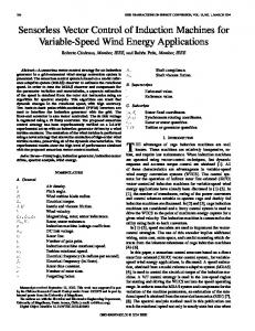
6 Fig. 3 shows the characteristics of the wind turbine power coefficient with the tip-speed ratio at different values of the blade pitch-angle. It is clear from the figure that there is a certain value of the tip-speed ratio at which the power coefficient is maximized. This value is known as the optimal value of the tip-speed ratio, λopt. Hence, a maximum mechanical power can be obtained from the wind turbine.
The electromechanical equation of the overall wind-driven BDFRG system referred to generator side can be expressed as: 13 On the other hand, the active-power expressions of the power and control windings are given by: 14 15 V. SENSORLESS SCALAR V/F CONTROL TECHNIQUE FOR MAXIMUM WIND-POWER EXTRACTION
Fig. 3. Characteristics of the wind-turbine power coefficient with the tipspeed ratio at different values of the blade pitch-angle
B. System Dynamic Modeling In an arbitrary reference frame, the BDFRG dq-model is expressed as [3]: The dq-axis voltage equations of the power and control windings can be written as:
It is well known that, in order to extract the maximum power from the wind turbine, the tip-speed ratio must equal its optimal value. Therefore, the generator speed should vary with wind-speed variations to maintain the tip-speed ratio at that proper value according to (3). Moreover, it is obvious from (1) that for a constant power-winding frequency (grid connected), the control-winding frequency should be varied to vary the rotor speed of BDFRG. In this paper a proposed scalar V/f control technique is used to achieve this strategy. A shaft-mounted speed encoder is required for closed-loop speed control drive systems. Generally, the speed encoder is undesirable in most drive systems because it adds cost and reliability problems, besides the need of shaft extension and mounting arrangement.
7
It is possible to estimate the speed signal from the machine voltages and currents with the help of a Digital Signal Processing (DSP). Aiding with the generator voltages and currents, the rotor speed of BDFRG can be estimated as follows [11]:
8
The three-phase flux linkages of power winding can be obtained as:
where
9 In addition, the corresponding flux linkage relations are given by:
16 where 0 0 0
10
0 0
17
0
The flux linkages and currents of the power and control windings can be expressed in a space-vector form as:
18
closing the switches S2 and S3 and opening the switches S1 and S4.
where 19 The electrical rotor position, as follows: ,
can be retrieved from [11] 0 20
2 ,
0
where 21 Hence, the electrical rotor angular speed, determined as:
can be
Fig. 4. Main structure of the proposed sensorless scalar V/f control system for maximum wind-power extraction
The command expressed as:
control-winding
frequency
22 2
where where 23 From which, the BDFRG mechanical rotor angular speed, is given by: 24 It should be noted that this approach of speed estimation is very simple and does not require Luenberger-type PI observer as used in [11]. Therefore, it is expected that using this approach in the proposed scalar control system for maximum wind-power extraction would result in a significant reduction in the overall system cost. Fig. 4 shows the main structure of the proposed sensorless scalar V/f control system for maximum wind-power extraction. In addition to extract the maximum power from the wind turbine, the presented control system aims at limiting the starting current of the control winding below the rated value of the used converter. This is due to a reduced power rating of the control winding converter. In order to achieve a good soft starting, the BDFRG is started as an induction machine by shorting the controlwinding terminals using the auxiliary switches S1 and S2 as shown in Fig. 4. In other words, S1 is closed and S2 is opened during this period up to reaching a speed approximately equals the rated value. Then, the bi-directional converter is switched into the control windings with a command frequency evaluated directly from the command generator speed by
can
be
25
denotes the command generator speed.
After these two steps for soft starting, the proposed scalar V/f control system will be activated by closing the switches S2 and S4 and opening the switches S1 and S3. The reference generator speed, can be evaluated directly by setting the optimal tip-speed ratio and measuring the wind speed. The evaluated reference speed is then compared to the estimated generator speed and the error is controlled using a simple PIcontroller for getting the command generator speed as shown in Fig. 4. Aiding with (25) the command control frequency can be easily determined, from which the required gating signals of the machine-side converter, shown in Fig. 4, can be obtained using sinusoidal PWM technique. In order to enable the bi-directional power flow between the grid side and the control winding, the grid-side converter, shown in Fig. 4, should be controlled. A step-down transformer, shown in Fig. 4, is required to match the voltage level between the DC link and the grid-side terminals. The main objective of the grid-side converter is to keep the DC link voltage at a constant appropriate level regardless of the magnitude and direction of the control-winding power. VI. SIMULATION RESULTS In order to confirm the validity of the proposed control technique, a sample of simulation results is introduced. The presented simulation results are obtained based on a six/twopole, 4.5 kW BDFRG driven by an appropriate wind turbine. All data related to the overall system parameters are listed in the appendix section [3].
It can be observed from Fig. 3 that the optimal tip-speed equals 8.1 and the ratio of the employed wind turbine corresponding maximum power coefficient, equals 0.48 at zero value of blade pitch-angle. The torque-speed profile of the wind-driven BDFRG is presented in Fig. 5 indicating the optimal values of BDFRG mechanical-torque and the corresponding rotor speed according to the optimal tip-speed ratio.
It can be observed that the converter over-current is completely avoided when the converter is switched into the control windings after a small short-circuit period of 2.5 seconds. Fig. 8 shows the estimated rotor-speed response and the corresponding speed-estimation error (difference between the actual and the estimated rotor speed) of the BDFRG. It can be observed from the speed-estimation error, shown in Fig. 8, that the estimated generator speed is in a good accordance with the actual generator speed which confirms the validity of the proposed approach for speed estimation. The response of the BDFRG electromagnetic torque is shown in Fig. 9. In addition, the response of wind-turbine power-coefficient and the corresponding active-power components which is contributed by both the power and the control windings are shown in Fig. 10.
Fig. 5. Torque-speed profile of the simulated wind-driven BDFRG
In the simulation process, the capability of maximum wind-power extraction using a sensorless scalar V/f control has been studied for wind-speed variations shown in Fig. 6.
Fig. 8. Estimated BDFRG rotor-speed response and the corresponding speed-estimation error
Fig. 6. Wind-speed variations
Firstly, the BDFRG is freely accelerated with shortcircuited control-winding terminals for soft starting purpose up to 2.5 seconds. Then, the partially power-rating converter is switched into the control windings of the generator with a command control frequency evaluated directly aiding with (25), using the estimated generator speed during the short circuit period. During this period, a simple PWM technique is used to control the voltage and frequency of the control winding up to 5.5 seconds. Hence, a complete scalar V/f closed-loop control system is activated for maximum windpower extraction. The response of the control-winding phasecurrent during different periods is shown in Fig. 7.
Fig. 9. Generator electromagnetic torque
Fig. 10. Response of wind-turbine power-coefficient and the corresponding active-power components of the power and the control windings Fig. 7. Response of the control-winding phase-current
It can be observed from Fig. 9 that the response of the generator electromagnetic torque has been changed for wind-
speed variations to track the optimal values, shown in Fig. 5, for maximum wind-power extraction.
APPENDIX BDFRG Parameters [3]:
The negative sign associated with the BDFRG electromagnetic torque and the corresponding active power of the power winding, shown in Fig. 9 and Fig. 10 respectively, proves that the machine is effectively in generating mode. In addition, the active-power response of the control winding, shown in Fig. 10, ensures the bi-directional operation of the control winding converter.
Rated Line Voltage Rated Frequency Rated Current
Table I summarizes the system behaviour under different operating conditions using the proposed control strategy. TABLE I.
SIMULATION RESULTS OF THE PROPOSED CONTROL METHOD Soft Starting Steps
Operating Region
Short circuited control winding
Switching the converter into the control winding
0 to 2.5
2.5 to 3.5
3.5 to 5.5
5.5 to 8
8.5 to 16.5
17 to 20
Wind speed (m/s)
4.5
4.5
5.2
5.2
5.6
5.3
Control-winding frequency (Hz)
-2.283
-0.83
-1.47
-1.33
-4.4
-1.6
784.25
755
766
763
823
770
0.423
0.44
0.478
0.48
0.48
0.48
-14.7
-15.5
-26.8
-26.5
-31
-27.5
BDFRG electromagnetic torque (N.m)
Wind Turbine Parameters [3]:
Closed Loop Control System for Maximum Wind-Power Extraction
Time (s)
Estimated BDFRG rotorspeed (rpm) Power coefficient
Rotor Inertia, Jg
The simulation results shown in Table I describe the system behaviour in both soft starting steps and closed loop control system for maximum wind-power extraction. The obtained results ensure the effectiveness of the proposed sensorless scalar-control strategy to maintain the tipspeed ratio at its optimal value under wind-speed variations. VII. CONCLUSIONS This paper has proposed a sensorless scalar V/f control strategy for maximum wind-power extraction of a gridconnected wind-driven BDFRG under wind-speed variations. In addition, the over-current of the employed converter has been avoided using a suggested soft starting method. The presented simulation results show a good transient response using the proposed control technique along with wind-speed variations. A close correlation between the estimated generator speed and the actual generator speed has been observed, which verifies the validity of the proposed speedestimation approach. In addition, the results ensure the capability of the presented control system for maximum windpower extraction of the proposed wind-generating system using a sensorless scalar-control strategy.
380 V 50 Hz 7.5 A 3.781 Ω 2.441 Ω 0.41 H 0.316 H 0.3 H 0.2 kg.m2
Rated Power Turbine Radius, R Wind Speed Range Turbine Inertia, Jr Gearbox Ratio, ng
6.0 kW 4.0 m 2 – 12 m/s 1.5 kg.m2 7.5
REFERENCES [1]
B. Wu, Y. Lang, N. Zargari, and S. Kouro, "Power Conversion and Control of Wind Energy Systems," Wiley-IEEE Press, 2011. [2] M. G. Sugirtha, and P. Latha, "Analysis of power quality problems in grid connected wind power plant," 2011 International Conference on Recent Advancements in Electrical, Electronics and Control Engineering, 15-17 Dec. 2011, pp. 19-24. [3] M. G. Mousa, S. M. Allam, and E. M. Rashad, "Maximum power tracking of a grid-connected wind-driven brushless doubly-fed reluctance generator using scalar control," The 8th IEEE GCC Conference and Exhibition, Muscat, Oman, 1-4 Feb. 2015, pp. 1-6. [4] S. M. Allam, A. M. Azmy, M. A. El-Khazendar, and A. L. Mohamadein, "Dynamic analysis of a BDFIM with a simple-proposed modification in the cage-rotor," The 13th International Middle-East Power Systems Conference (MEPCON'2009), Egypt, Vol. 1, Dec. 2009, pp. 356-360. [5] B. Hopfensperger, and D. J. Atkinson, "Doubly-fed a.c. machines: classification and comparison," European Power Electronics Conference, EPE 2001, PP. P1-P17. [6] F. Liang, L. Xu, and T. A. Lipo, "d-q analysis of a variable speed doubly ac excited reluctance motor," Electrical Machines and Power Systems, Vol. 19, No. 2, Mar. 1991, pp. 125-138. [7] R. E. Betz and M. G. Jovanovic, "Introduction to the space vector modelling of the brushless doubly-fed reluctance machine," Electric Power Components and Systems, Vol. 31, No. 8, 2003, pp. 729–755. [8] F. Valenciaga and P. F. Puleston, "Variable structure control of a wind energy conversion system based on a brushless doubly fed reluctance generator," IEEE Transactions on Energy Conversion, Vol. 22, No. 2, June 2007, pp. 499–506. [9] L. Xu and Y. Tang, "A novel wind-power generating system using field orientation controlled doubly-excited brushless reluctance machine," Proceeding of the IEEE IAS Annual Meeting, 1992, pp. 408–413. [10] D. Rekioua, "Wind Power Electric Systems Modeling, Simulation and Control," Green Energy and Technology, 2014. [11] M. Jovanovic, "Sensored and sensorless speed control methods for brushless doubly fed reluctance motors," IET Electric Power Applications, Vol. 3, No. 6, 2009, pp. 503–513.