Operating-System Controlled Network on Chip∗ Vincent Nollet
[email protected]
Theodore Marescaux ´
[email protected]
†
Diederik Verkest
[email protected]
IMEC vzw. Kapeldreef 75 3001 Leuven, Belgium
ABSTRACT Managing a Network-on-Chip (NoC) in an efficient way is a challenging task. To succeed, the operating system (OS) needs to be tuned to the capabilities and the needs of the NoC. Only by creating a tight interaction can we combine the necessary flexibility with the required efficiency. This paper illustrates such an interaction by detailing the management of communication resources in a system containing a packet-switched NoC and a closely integrated OS. Our NoC system is emulated by linking an FPGA to a PDA. We show that, with the right NoC support, the OS is able to optimize communication resource usage. Additionally, the OS is able to diminish or remove the interference between independent applications sharing a common NoC communication resource.
Categories and Subject Descriptors C.2.1 [Network Architecture and Design]: Packet switching networks; C.2.3 [Network Operations]: Network management, network monitoring
heterogeneous processing elements (PEs), also denoted as tiles. These tiles will be interconnected by a Network-onChip (NoC) [1, 2, 5]. The general problem of mapping a set of communicating tasks onto the heterogeneous resources of such a platform while dynamically managing the communication between the tiles is an extremely challenging task. In a NoC environment, the OS is able to control the inter-processor communication. This ability should ensure that granted compute power matches the communication needs, in order to provide the required quality of service. The rest of the paper is organized as follows. Section 2 provides a description of the emulated target platform and the employed NoC. Section 3 describes the different communication management tools used by the OS. Section 4 details a case study, showing the communication interaction between two distinct applications executing on the target platform. It also illustrates how undesired behavior is managed by the OS. Finally Section 5 concludes. Related work [1, 5, 6] is discussed throughout the paper.
2. General Terms Management, Measurement, Performance
Keywords Network on Chip, Operating System, MP-SoC
1. INTRODUCTION In order to meet the ever-increasing design complexity, future sub-100nm platforms [1] will consist of a mixture of ∗Part of this research is funded by the European Commission (IST-AMDREL project IST-2001-34379) by the Flemish Government (GBOU-RESUME project IWT-020174RESUME) and by Xilinx Labs, Xilinx Inc. R&D group. †Also professor at the VUB and at the KU-Leuven.
Permission to make digital or hard copies of all or part of this work for personal or classroom use is granted without fee provided that copies are not made or distributed for pro£t or commercial advantage and that copies bear this notice and the full citation on the £rst page. To copy otherwise, to republish, to post on servers or to redistribute to lists, requires prior speci£c permission and/or a fee. DAC’04, June 7–11, 2004, San Diego, California, USA. Copyright 2004 ACM 1-58113-828-8/04/0006 ...$5.00.
SYSTEM DESCRIPTION
This section provides an overview of the system and of the components involved in communication management.
2.1
Multiprocessor NoC Emulation
Our multiprocessor system is emulated by linking a StrongARM processor, present inside a Compaq iPAQ PDA, to an FPGA by means of the iPAQ expansion port. The FPGA contains the slave processors, the NoC and the master ISP interface component (Figure 2). Our packet-switched NoC, called data NoC, is implemented as a 3x3 bidirectional mesh and is responsible for delivering data packets for tasks executing on the PEs. A second NoC, the control NoC, is used for OS-control messages [3] (Figure 1a). Separation of both NoCs ensures that application data circulating on the data NoC does not interfere with OS control messages. Both NoC’s are clocked at 30 MHz, while the StrongARM processor, present in the PDA, is clocked at 206 MHz.
2.2
NoC Network Layer
The presented data NoC is a packet-switched network. The routers in the network use virtual cut-through switching and output buffering. The deterministic routing algorithm is based on a OS-reconfigurable lookup table. It guarantees inorder packed delivery, hence avoiding the packet reordering overhead required by the proposal of Guerrier et al. [6].
2.3 NoC Transport Layer 2.3.1
S S
Data Network Interface Component
The PEs of our SoC are interfaced to the packet-switched data NoC by means of a data Network Interface Component (dNIC). From the PE viewpoint the main role of the dNIC is to buffer input and output messages and to provide a highlevel interface to the data router (Figure 1a). The dNIC is also responsible for collecting communication statistics. This involves keeping track of the number of messages sent, received and blocked. The blocked message count denotes the number of received messages, that were blocked in the data router buffer while waiting for the PE input buffer to be released. Moreover, the dNIC implements an injection rate control mechanism, allowing control of the amount of messages the attached PE injects in the data NoC per unit of time [3]. Data NoC
Core OS
Core OS
Control NoC
(1) Control Router
Data Router
Control NIC
Data NIC
Processing Element (PE) a.
Local OS
(8)
(5)
cNIC i stub (2)
(4)
cNIC i stub (7)
(6)
Control NoC
(3)
Control NoC
Master ISP
Slave i b.
Figure 1: (a) dNIC and cNIC connect the PE to data and control NoCs respectively. (b) Remote execution of an OS function call on a slave node.
Base RTOS
Control Network Interface Component
Each node in our system is also connected to a control Network Interface Component (cNIC). A main role of the cNIC is to provide the OS with a unified view of the communication resources. For instance, the message statistics collected in the dNIC are processed and communicated to the core OS by the cNIC (Figure 1a). The cNIC also allows the core OS to dynamically set the routing table in the data router or to manage the injection rate control mechanism of the dNIC. Another role of the cNIC is to provide the core OS with an abstract view of the distributed PEs. Hence, it is considered as a distributed part of the OS. This role of the cNIC is discussed in-depth in [3].
2.4 Operating System One of the PEs of our multi-core SoC is denoted as master because it executes the core of the OS. Besides monitoring the behavior of the global system, this mainly involves assigning tasks to the other PEs in the system (the slaves). Additionally, every slave node contains limited local operating system functionality (Figure 2a). The close interaction between the core of the OS and the slave OS functionality, resembles classic remote procedure calling (RPC). The operating system maintains for each cNIC a structure that describes its functionality and that allows the OS to remotely execute a function on a slave node. So the cNIC structure in the OS can be seen as the RPC stub. Figure 1b illustrates how the slave OS function-
Master ISP
S
S
S S
S
S
S
Master ISP
S
S
S
S
S
S S a.
Computing resource OS functionality
b.
Figure 2: The core OS solely executes on top of the master ISP. The slaves (S) have their own local OS functionality.
ality is used. First of all, the OS makes a function call to the respective cNIC stub (1) . This stub translates the call into a control message containing the desired function number and its required parameters. Consequently, this message is sent to the slave node (2) . Once the message is received on the slave node (3) , its function number and parameters are unwrapped and the respective local OS function executes at the slave node (4) . The return value (5) is packed into a message (6) , sent over the control network to the cNIC stub, where it is unpacked (7) . Finally, the original core OS function call returns with the respective return value (8) . Certain network events (e.g. synchronization) require action from the core OS. The slave node initiates then a function call toward the core OS using the same mechanism.
3. 2.3.2
Operating System
S
NOC CONTROL TOOLS
This section illustrates the tools used by a distributed, NoC-aware OS to manage SoC communication.
3.1
Dynamic Statistics Collection
The OS monitors NoC communication by polling the cNICs through a remote function call to obtain the traffic statistics. (cf. Section 2.3). Statistics such as the blocked message count are important: these messages potentially disturb other data traffic sharing the same channel. Blocked messages occur when the receiving PE is unable to process its input fast enough. The OS is able to solve this blocking issue by forcing the source of the messages to send fewer messages per time unit or by avoiding the congested link. The NoC tools that enable these solutions are presented in the following sections.
3.2
Dynamic Injection Rate Control
By providing a message injection rate control function, the dNIC allows the OS to limit the time wherein a certain processor is allowed to send messages onto the network. This time is called the send window of the processor. A similar traffic rate control mechanism was used by Kumar et al. [1]. By setting the low and high value, the OS is able to describe a single send window within the whole send spectrum (Figure 3a). However, by also using a modulo value, this single send window can be spread over the whole send spectrum (Figure 3b and Figure 3c). Setting a window is deterministic and fast: it takes on average 57 µs to change the window values of a certain PE.
a. 0
L
0
L
H
T
M
T
b. H
c. 0
L
H
M
6), that consumes messages slower than they are produced. The chosen production/consumption message ratio guarantees that the NoC router of the message sink reaches a saturation level and hence severely impacts other communication flows sharing the same channel (Figure 4).
T
Send window, sending messages allowed
0
Huff
Figure 3: The OS can specify the size, the location and the amount of spreading of the ’send window’ by adjusting the low (L), high (H) and modulo (M) value.
0
1
2
3
4
5
6 msg sink 6
3.3 OS-controlled Adaptive Routing
4. NOC MANAGEMENT CASE STUDY This section describes and characterizes two applications that concurrently share communication resources of the NoC. Additionally, this section illustrates how the OS can manage communication interference between the applications.
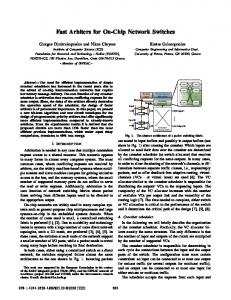
4.1 Application Description The main application in this case study is a Motion-JPEG video decoder. It is composed of four tasks running concurrently on the PEs of the platform (Figure 4). Two of these tasks, the sender and the receiver, run on the StrongARM processor (tile 3). The two other tasks, are hardware blocks: a task that performs the huffman decoding and the dequantisation, further denoted as Huffman block (tile 1), and a task that performs a 2D-IDCT and a YUV to RGB conversion, further denoted IDCT block (tile 8). To evaluate the influence of communication interference between applications, we also designed a synthetic application, composed of a message generator (tile 7), that produces traffic at a constant rate, and a message sink (tile
8 IDCT 7
8
Video decoder communication Synthetic appl. communication
Figure 4: Mapping of Motion-JPEG application and synthetic traffic generating application on the platform. Communication channel 7 → 6 is shared. The communication of the video decoder (without interference), has been characterized by means of the message statistics (Figure 5). The core OS samples the relevant cNICs once every 20 ms. 4
Stack Plot of IDCT
x 10 4
Number of messages
The OS can also manage communication by changing the routing table of a router in order to divert a message stream from one channel to another. Since it is a complex operation, the OS requires three steps to change a routing table. The first step performs a synchronization of every flow passing through router R on output O in order to clear these channels and thus assure in order delivery of messages. This is achieved by sending a synchronization request to every source task and waiting on a synchronization acknowledge from the receiving side, indicating that the channel is empty. The second step updates the routing tables. In the third step, the operating system notifies all previously synchronized tasks to resume sending messages. A synchronization/release remote function call does not require any parameters and takes on average 53 µs. However, the actual time needed to perform a complete synchronization also depends on other parameters (e.g. channel congestion). The remote function to change a routing table takes as many parameters as there are entries in the routing table. For our 3x3 network (9 entries), changing a routing table requires on average 61 µs. Note that changing a routing table affects all streams passing through the router on the respective output. This means, for example, that satisfying the quality-of-service request for a single application, will potentially have a (minor) interference with another application.
7 msg gen.
relative window size blocked received sent
3.5 3 2.5 2
(Peak 1)
(Peak 2)
1.5 1 0.5 3.2
3.25
3.3
3.35 3.4 3.45 3.5 Time in OS Ticks (0.271 µs per tick)
3.55
3.6 9
x 10
Figure 5: Communication characterization of IDCT block in MJPEG video decoder. The same video sequence1 has been played twice with different windowing techniques. Peak(1) in Figure 5 has been obtained by applying a window spreading technique (Figure 3(b,c)) whereas the second peak was obtained by allocating continuous blocks of bandwidth (Figure 3a). In both cases the window size gradually decreases from 100% (98.85 MB/s when clocked at 50 MHz [4]) down to 0.0244% (approximately 25 KB/s). The window spreading technique clearly performs better: the throughput of the video decoder application only starts to decrease when the OS diminishes its effective window to less than 2% of the total bandwidth and reaches half of the throughput for a total allocated window of less than 1.5% (about 1.5 MB/s). In the case of the nonspreading technique, half-throughput is reached as soon as the allocated bandwidth is less than 75%. Adequate OS control of the communication can improve NoC performance by a factor of 50! The communication characteristics of the synthetic application, when using window spreading, are shown in Figure 1 For Peak(2) we show statistics on a truncated videosequence because the quickly decreasing bandwidth considerably reduces the frame-rate and thus increases the time to completion.
4
(a) Spreading Window Allocation: Stack Plot of IDCT
x 10
7b. As expected, the message sink blocks as many messages as it receives. Only when the allocated bandwidth is decreased below 0.05% that the blocking behavior stops.
1−gen
win
Number of messages
3.5
blocked received sent
3 2.5 2 1.5 1 0.5
4.2 OS Communication Management
2.28
4
Number of messages
blocked received sent
3
2
1
0 3.6
3.65
3.7
3.75
3.8
3.85
3.9
3.95 9
x 10 (b) Block Window Allocation: Stack Plot of Message Sink
Number of messages
2.34
2.36
2.38
2.4
2.42
2.44 9
(a) Block Window Allocation: Stack Plot of IDCT
x 10
2.32
x 10
2000
IDCTwin Genwin
1500
blocked received
(b) Spreading Window Allocation: Stack Plot of Message Sink gen
win
2000
Number of messages
After placing the video application tasks, we have mapped the message generator and message sink from the perturbing application on tiles 7 and 6 respectively (Figure 4). This way, the perturbing application will congest the communication channel (7 → 6) it shares with the video decoding application. Measurements have been performed for both bandwidth allocation techniques: window-spreading (Figure 7) and block-allocation windows (Figure 6). The effect of diminishing window size is clear on the message sink task in the case of the continuous-window allocation: the amount of messages sent is directly proportional to the injection rate window set (Figure 6b). Optimal Video Decoder performance is obtained when less than 1% of the total bandwidth is allocated to the message generator (Figure 6a, time interval [3.91e9;3.95e9]). The OS can trade-off performance between both applications by changing their respective injection rates. When using the window-spreading 4
2.3
blocked received
1500 1000 500 0 2.28
2.3
2.32
2.34
2.36
2.38
2.4
2.42
2.44 9
x 10
Figure 7: Window spreading on channel 7 → 6.
5.
CONCLUSION
This paper features an OS that can manage communication on a packet-switched Network-on-Chip (NoC). Thanks to its tight coupling with OS-support functionality distributed in the NoC, the OS can optimize communication resource allocation and thus minimize interaction between concurrent applications. The three main OS tools provided by the NoC are: the ability to collect data traffic statistics, the ability to limit the time interval in which a processing element (PE) is allowed to send (called injection rate control) and, finally, the ability to dynamically adapt the routing in the NoC. A case study of a video decoding application and a synthetic traffic generator, running on our multi-processor emulation platform, illustrates how the OS can optimize channel usage (by a factor of 50) and manage communication interference using the injection rate control tool.
1000
500
0 3.6
6. 3.65
3.7
3.75
3.8
3.85
3.9
ADDITIONAL AUTHORS
3.95 9
x 10
Figure 6: BW allocated in blocks on channel 7 → 6.
Additional authors: Jean-Yves Mignolet and Serge Vernalde, IMEC v.z.w., email: (mignolet,vernalde)@imec.be.
7. technique, the effect of diminishing the total window size is not directly proportional to the bandwidth allocated and the trade-offs obtained in the previous case are not possible (Figure 7b). However, using window-spreading has other advantages: jitter is greatly reduced because communications are evenly spread over time. Moreover, a proper window setting can hide the latency of the receiver side and completely suppress blocking on the network. In Figure 7b at the OS time-stamp 241e7, the message sink task no longer causes message blocking in the NoC. This happens when the window of the message generator is less than 0.02% of the total bandwidth. Note that the message sink, is not disturbed by this window reduction: it still consumes 40000 messages per second. The OS has simply matched the window size to the optimal sending rate in the perturbing application. As a consequence, thanks to the bandwidth saved by the OS, the video decoder reaches its optimal frame-rate. Besides the injection rate control mechanism, the OS can also solve interference issues between applications in other ways. First of all, as Section 3.3 explains, it is possible to avoid the congested link by rerouting the video application stream. Additionally, the OS can decide to dynamically migrate the message generator task to another node in the NoC.
REFERENCES
[1] S. Kumar, A. Jantsch, M. Millberg, J. berg, J. Soininen, M. Forsell, K. Tiensyrj, and A. Hemani, ”A network on chip architecture and design methodology,” Proc. IEEE Computer Society Annual Symposium on VLSI, Apr. 2002. [2] T. Marescaux, A. Bartic, D. Verkest, S. Vernalde, R. Lauwereins, ”Interconnection Networks Enable Fine-Grain Dynamic Multi-Tasking on FPGAs.”, pages 795-805, Proc. FPL 2002. [3] T. Marescaux, J-Y. Mignolet, A. Bartic, W. Moffat, D. Verkest, S. Vernalde, R. Lauwereins: Networks on Chip as Hardware Components of an OS for Reconfigurable Systems, Proc. FPL 2003. [4] T.A. Bartic, J-Y. Mignolet, V. Nollet, T. Marescaux, D. Verkest, S. Vernalde, R. Lauwereins, Highly Scalable Network on Chip for Reconfigurable Systems, Systems on Chip Conference, pages 79-82, Tampere, 2003. [5] A. Jantsch and H. Tenhunen, ”Will Networks on Chip Close the Productivity Gap”, Networks on Chip, pages 3-18, Kluwer Academic Publishers 2003. [6] Pierre Guerrier, Alain Greiner, ”A Generic Architecture for On-Chip Packet-Switched Interconnections”, pages250-256, Proc. DATE 2000.