Optical Signal-to-Noise Ratio Monitoring Using Uncorrelated Signal-Spontaneous Beat Noise W. Chen, R. S. Tucker, J. S. Evans and W. Shieh ARC Special Research Centre for Ultra-Broadband Information Networks (CUBIN) an affiliated program of National ICT Australia (NICTA), Australian Photonics CRC, Photonics Research Laboratory, Department of Electrical and Electronic Engineering, The University of Melbourne, VIC 3010, Australia Email: w.
[email protected]
Abstract— Optical performance monitoring is essential for managing both current and future optical networks. One important quantity to monitor is the optical signal-to-noise ratio (OSNR). Traditional optical spectrum analyzer (OSA) based measurements become problematic in dynamically reconfigurable wavelength-division multiplexing (WDM) networks. We propose a new method based on analyzing the uncorrelated signalspontaneous beat noise and show through simulation that in the OSNR range from 10 dB to 25 dB, the OSNR estimation error can be less than 0.6 dB.
I. INTRODUCTION Interest in optical performance monitoring (OPM) first took hold in the early 1990s with the introduction of WavelengthDivision Multiplexing (WDM) systems. As people began to think more about optical networks rather than optical transmission systems, it became clear that a solution would be needed for the monitoring problem [1]. WDM optical networks have enabled the rapid growth of data traffic in the network backbone. Further increases in capacity can be gained by moving to dense wavelength division multiplexing (DWDM) with large channel counts. Optical performance monitoring is essential for managing such high capacity optical transmission and switching systems [1]. Optical performance monitoring describes an extremely wide range of functionality intended to be included in a communication network to improve the network’s performance [2]. Both current and future WDM or DWDM optical networks require reliable and economical methods for performance monitoring without interrupting the client connections. For the efficient operation and maintenance of the network, it is essential to monitor various parameters including the wavelength, optical power, optical signal-tonoise ratio (OSNR), and optical paths, etc. [3]. The widespread use of optical amplifiers has enabled longhaul optical communication systems [4], but the cascading of a large number of amplifiers in such systems introduces amplified spontaneous emission (ASE) noise into the optical signals which degrades the OSNR [2]. OSNR is a significant factor for the quality of optical systems and OSNR monitoring is essential for optical performance monitoring. For example, OSNR monitoring is necessary for fault management including fault localization and diagnosis. In order to localize
OSNR degradation faults, network operators require multiple truck rolls along the entire length of the optical segments. In ultra-long-haul networks, diagnosing these faults without OSNR monitoring may be challenging and optical add-drop multiplexers (OADMs) complicate the situation further [5]. Quite a few techniques have been developed to monitor OSNR. Current OSNR Monitoring Techniques can be classified into two groups. One is OSNR monitoring by measuring the ASE noise outside of the channel bandwidth. To simplify the name, we can call this group of techniques out-of-band OSNR monitoring. The other is OSNR monitoring by measuring the ASE noise inside the channel bandwidth which is called in-band or in-channel OSNR monitoring. Out-of-band OSNR Monitoring includes the traditional optical spectrum analyzer (OSA) based OSNR estimation [6], [7] and some techniques using arrayed waveguide grating (AWG) circuits [8]– [10]. The traditional optical spectrum analyzer (OSA) based OSNR estimation [6], [7] relies on interpolation of ASE levels adjacent to the channel of interest to obtain the approximate ASE level in the channel. As the interpolated ASE noise may not be the real ASE noise in the channels of interest, those conventional linear interpolation techniques may not monitor the OSNR accurately for a dynamically reconfigurable WDM network. This is because in a dynamically reconfigurable WDM network each channel may traverse through different route and different number of EDFA’s so that the network has unflat ASE spectrum. As the principle of the techniques using arrayed waveguide grating (AWG) circuits [8]–[10] was also based on measuring the ASE noise between the channels, the AWG monitoring circuits may not precisely measure OSNR in presence of multi-path interference effects and OADM/OXC (Optical Cross Connect) networking [1]. Polarization nulling method [11]–[14] is one of the in-band OSNR monitoring approaches. But its performance is limited by Polarization Mode Dispersion (PMD). Even if PMD effects can be compensated, polarization scattering in ultra long-haul systems results in fast bit-to-bit polarization fluctuations that are impractical to track [1], [15]. In addition, the speed of OSNR monitoring will be limited by the polarization controller. Another in-band OSNR monitoring approach is the low frequency beat noise measurement [16]. The method is simple to implement by
two photo-detectors and a DSP board to measure the beat noise in the low frequency range, and OSNR can be measured accurately for dynamically reconfigurable optical networks. The disadvantage of the low frequency beat noise approach is that it may not be applicable for the very random data or data modulated with long pattern length. This is because the beat noise was measured below a certain frequency f , which equals to the ratio of bit rate and PRBS pattern length, if f is too small, it is hard to obtain the beat noise. For example, if the data is modulated at 10 Gb/s with PRBS of pattern length 231 − 1, f will be around only 5 Hz, which means that we have to measure the noise below 5 Hz in the RF spectrum. In this paper, we propose a novel OSNR monitoring method by using the uncorrelated signal-spontaneous beat noise. Compared with the linear interpolating methods [6], [7], the use of costly narrow bandwidth optical filters is avoided by applying optical filters with broad bandwidth and more processing in the electrical domain. And we do not need to employ polarization controller and polarization beam splitter as in the polarization nulling method [13]. In addition, unlike the method utilizing the low frequency noise characteristics at the receiver [16] which may not be applicable for the very random data or data modulated with long pattern length, our method does not have the pattern length limitation. The good OSNR monitoring performance of this approach is supported by our simulation results. The paper is organized as follows. Section II describes the principle of the method, including the schematic, analysis and some equations. Section III shows some simulation results. Section IV gives out the sensitivity analysis and discussion on some practical issues related to the method. Section V draws the conclusion.
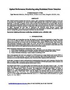
Fig. 1.
Schematic layout of proposed OSNR monitoring method.
to be tuned to the proper positions so that the signal component in the electrical domain can be removed by subtraction. One possible position for the two optical filters relative to the modulated optical signal is depicted in Fig. 2, where fc is the optical carrier frequency and fb is the bit rate. Both optical filters cover the main lobe of the optical signal spectrum. Our description and discussion later on will base on the filters’ structure in Fig. 2.
II. METHOD DESCRIPTION As we know, optical amplifiers introduce ASE noise into transmission systems. At the receiver, beat noise is generated by beating between the signal and ASE noise which is signalspontaneous (sig-sp) beat noise. Beating between ASE noise and ASE noise results in spontaneous-spontaneous (sp-sp) beat noise. Usually signal-spontaneous beat noise is the dominant beat noise. Our OSNR monitoring method is based on using uncorrelated signal-spontaneous beat noise. A. Principle of the Proposed OSNR Monitoring Method Fig. 1 illustrates the schematic layout of the proposed OSNR monitoring method. Within the OSNR monitoring module, which performs estimating OSNR for each WDM channel, the modulated signal and ASE noise are split into two parts by a 3dB coupler. Then the two parts are sent into two optical tunable bandpass filters (BPF1 and BPF2) with the same optical bandwidth Bo and different center frequencies fo1 , fo2 , respectively. The two optical tunable bandpass filters perform to select the channel of interest and the information for OSNR monitoring. A power meter is used to measure the total optical power after BPF1. This power level is used to calculate the OSNR. In this method, the two optical filters need
Fig. 2.
Two optical filters position relative to the modulated optical signal.
In the above paragraph, the optical part of our method was described. This paragraph explains the electrical part of the system. Refer to Fig. 1, two optical filters are followed by two photodiodes (PD). Then the spectrum detected by the two photodiodes are subtracted. At last, an RFSA and digital signal processor (DSP) are utilized to estimate OSNR. The concept of the uncorrelated sig-sp beat noise method is that the signal is correlated while the ASE noise in different frequency bandwidth is uncorrelated. This property means that the beating between signal and ASE noise within different bandwidth (sig-sp beat noise) is uncorrelated. Therefore, by applying two optical filters with the same bandwidth but different center frequencies and subtracting the data detected by the two photodiodes, the signal components and correlated sig-sp beat noise can be removed, while the uncorrelated sig-sp
beat noise will add to each other in the same frequency range, then we can observe the sig-sp beat noise in RFSA and process the uncorrelated sig-sp beat noise power density in DSP to estimate the OSNR. Since sig-sp beat noise is the dominant beat noise, sp-sp beat noise is neglected in our analysis.
shown in Fig. 3 (a) and (b). While in the other portion of the two optical filters (Fig. 2: fc −3fb to fc −fb and fc +fb to fc + 3fb ), the ASE noise is uncorrelated, hence the sig-sp beat noise is uncorrelated in the electrical frequency range from fb to 3fb as shown in (a) and (b) of Fig. 3. Therefore, after subtraction the data from two photodiodes, the uncorrelated portion of sigsp beat noise will add to each other in the electrical frequency range from fb to 3fb , but the signal components together with the correlated portion of the sig-sp beat noise in the frequency range from 0 to fb will disappear as shown in (c) of Fig. 3. B. OSNR Calculation The noise power density Nnoise observed in the RFSA consists of shot noise (Nshot ), thermal noise (Nthermal ), circuit noise (Ncircuit ) and beat noise (Nbeat ). As shot noise, thermal noise and circuit noise are regarded as non-beat noise, Nnoise can be described as Nnoise = Nbeat + Nshot + Nthermal + Ncircuit = Nbeat + Nnon−beat
(1)
In order to obtain the beat noise power density, the non-beat noise power density can be measured at high OSNR (> 30 dB) then subtracted from the measured total noise power density as implemented in [16]. According to the theory of beat noise [17], [18], the sig-sp beat noise power density in the frequency range from fb to 3fb with the assumption of polarized signal and unpolarized ASE noise is given by 2 2r2 Psig (2) R · OSN R where OSN R is the optical signal-to-noise ratio measured with the resolution bandwidth R; r is the responsivity of photodiode; Psig is the optical signal power; and SASE is the ASE spectral density in a single polarization. As the signal power Psig is unknown, another equation is needed together with equation (2) to work out OSN R. The measured total power Ptotal after either BPF1 or BPF2 provides us the equation. In Fig. 1 the power meter is located after BPF1. Ptotal that consists of the signal power (Psig ) and the ASE power (PASE ) can be described as
Nsig−sp = 4r2 Psig SASE =
Bo ) (3) R · OSN R By equation (2) and (3), OSNR can be calculated by solving the following equation. Ptotal = Psig + PASE = Psig (1 +
(Bo2 Nsig−sp )
Fig. 3.
Signal-spontaneous beat noise spectrum.
1 1 2 + 2R(Bo Nsig−sp − r2 Ptotal ) 2 OSN R OSN R +Nsig−sp R2 = 0 (4) III. SIMULATION RESULTS
Fig. 3 explains the concept. In the overlapping portion of the two optical filters (Fig. 2: fc − fb to fc + fb ), the ASE noise is correlated so that the sig-sp beat noise is correlated in the frequency range from 0 to fb in the electrical spectrum as
A simulation for the uncorrelated sig-sp beat noise method was built in VPItransmissionMaker 5.5. The signal source was the CW laser modulated by a Mach-Zehnder modulator at fb = 10 Gb/s with the PRBS pattern length of 230 − 1. The
30
25
"Measured" OSNR (dB)
Difference between "Measured" OSNR and True OSNR(dB)
0.5
0
−0.5
−1
−1.5
−2 10
12
14
Fig. 5.
16
18
20 22 True OSNR (dB)
24
26
28
30
Error of “Measured” OSNR vs. True OSNR.
estimation results. The robustness of our method is tested by drifting the optical carrier frequency in the simulation. 6
5
OSNR estimation error (dB)
centre frequency of the carrier was fc = 193.1 THz and the modulated signal power was -3 dBm. The ASE source was additive white Gaussian noise (AWGN). The OSNR could be adjusted by the variable attenuators for the signal and ASE sources. In the simulation, the signal power was kept unchanged while the ASE noise power was attenuated to vary OSNR from 10 dB to 30 dB. The settings of the two optical tunable bandpass filters were according to Fig. 2. The bandwidth of the two filters was Bo = 4fb = 40 GHz, and the centre frequencies were fo1 = fc + fb and fo2 = fc − fb . The responsivities of the two photodiodes were set to 1 A/W. The resolution of RFSA was set to 1.22 MHz. In the RF range from 10 GHz to 30 GHz, there was the sum of the uncorrelated sig-sp beat noise spectrum. 197 points of the sig-sp beat noise power density were collected from 15 GHz to 15.24 GHz then averaged to obtain Nsig−sp and the OSNR was calculated by equation (4). Fig. 4 and Fig. 5 depict the “measured” OSNR vs. true OSNR and the OSNR estimation error vs. true OSNR, respectively. In the OSNR range from 10 dB to 25 dB, the estimation error is less than 0.6 dB. While the estimation error is about 1.8 dB when the true OSNR equals to 30dB. For higher OSNR, the error is caused by the fact that the small sig-sp beat noise could not be calculated accurately by equation (2), when the optical spectrum shape of the signal is not a single pulse which is the assumption for equation (2).
4
3
2
20
1
15
0
Fig. 6.
10
5 10
1
12
14
Fig. 4.
16
18
20 22 True OSNR (dB)
24
26
28
30
“Measured” OSNR vs. True OSNR.
IV. DISCUSSION In this section, we will analyze some factors which may affect the OSNR monitoring method by using the uncorrelated signal-spontaneous beat noise. The effect may come from either optical process or electronic process. A. Optical Carrier Frequency Drift The change of the relative position between optical signal spectrum and the optical filters will impact on the OSNR
1.5
2
2.5
3 3.5 4 Laser frequency drift (GHz)
4.5
5
5.5
6
OSNR Estimation Error vs. Optical Carrier Frequency Drift.
For the case of two optical filters covering the main lobe of the optical signal spectrum as shown in Fig. 2, Fig. 6 illustrates the OSNR estimation error vs. optical carrier frequency drift when the true OSNR is 20 dB. It can be seen that if the optical carrier frequency drifts within 3 GHz, the OSNR estimation error is within 1 dB. But as the optical carrier frequency drift increases, the OSNR estimation error will increase. Therefore, the method is robust for 2 or 3 GHz optical carrier frequency drift. B. Photodiodes Imbalance Calibration Imbalance of the two photodiodes will result in the residual of signal component after subtraction, which will affect on the OSNR estimation accuracy of our method. The imbalance of two photodiodes can be caused by the different photodiode responsivities and different power responses of the photodiodes.
Fig. 7 depicts the power responses of two photodiodes. It can be seen that at the same measurement frequency fm , the two photodiodes may have different power responses. Therefore it is essential to calibrate the imbalance.
Fig. 9.
Fig. 7.
Power response of two photodiodes.
Calibration can be carried out in either the optical process or the electronic process. There are three options for us to subtract the data after the two photodiodes – using differential amplifier, applying balanced photodiodes and utilizing DSP to perform the subtraction and calibration.
Fig. 8.
Electronic processes using balanced photodiode.
Fig. 10.
Electronic processes using DSP.
converters, two A/D converters for the two paths, then the digital data will be put into the DSP and processed by software for calibration, subtraction and OSNR calculation. For the schematic using DSP, it is very flexible to calibrate the imbalance by software, but two down converters and two A/D converters are required. For the schematics using differential amplifier and balanced photodiodes, it is not very flexible to calibrate the imbalance, but we need only one down converter and one A/D converter. Therefore, which schematic to choose depends on the applications.
Electronic processes using differential amplifier.
V. CONCLUSION Fig. 8 shows applying a differential amplifier to subtract the data from the two photodiodes. The analog data can be subtracted by using a differential amplifier. Following the differential amplifier, we have a down converter, an A/D converter and an OSNR calculation module. To calibrate the imbalance of the two photodiodes, we can either apply a variable optical attenuator before one photodiode as in Fig. 8 or apply a variable electrical attenuator between one photodiode and the differential amplifier. Fig. 9 describes applying balanced photodiodes to subtract the data from the two photodiodes. Following the balanced photodiodes, we have a down converter, an A/D converter and an OSNR calculation module. A variable optical attenuator before any of the photodiodes can be applied to calibrate the imbalance of the two photodiodes. Fig. 10 illustrates applying DSP to perform the calibration, subtract the data from two photodiodes, and calculate OSNR by software. After the two photodiodes, we have two down
We proposed a novel OSNR monitoring method by analyzing the uncorrelated signal-spontaneous beat noise. Two optical tunable bandpass filters are used and electronic signal processing is applied in the method. Simulation results showed that the OSNR estimation error can be less than 0.6 dB in the OSNR range from 10 dB to 25 dB. ACKNOWLEDGMENT This work was supported by the Australian Research Council. R EFERENCES [1] D. C. Kilper, R. Bach, D. J. Blumenthal, D. Einstein, T. Landolsi, L. Ostar, M. Preiss, and A. E. Willner, “Optical performance monitoring,” J. Lightwave Technol., vol. 22, no. 1, pp. 294–304, Jan. 2004. [2] S. Wielandy, M. Fishteyn, and B. Zhu, “Optical performance monitoring using nonlinear detection,” J. Lightwave Technol., vol. 22, no. 3, pp. 784–793, March 2004.
[3] Y. C. Chung, “Optical monitoring techniques for WDM networks,” in Electronic-Enhanced Optics, Optical Sensing in Semiconductor Manufacturing, Electro-Optics in Space, Broadband Optical Networks, 2000. Digest of the LEOS Summer Topical Meetings, 24-28 July 2000, pp. IV43–IV44. [4] Govind P. Agrawal, Fiber-Optic Communication Systems, Third Edition, John Wiley & Sons, Inc., New York, 3rd edition, 2002. [5] D. C. Kilper and W. Weingartner, “Monitoring optical network performance degradation due to amplifier noise,” J. Lightwave Technol., vol. 21, no. 5, pp. 1171–1178, May 2003. [6] K. Asahi, M. Yamashita, T. Hosoi, K. Nakaya, C. Konishi, and S. Fujita, “Optical performance monitor built into EDFA repeaters for WDM networks,” in Optical Fiber Communication Conference and Exhibit,Technical Digest, 22–27 Feb. 1998, pp. 318–319. [7] H. Suzuki and N. Takachio, “Optical signal quality monitor built into WDM linear repeaters using semiconductor arrayed waveguide grating filter monolithically integrated with eight photodiodes,” Electronics Letters, vol. 35, no. 10, pp. 836–837, 13 May 1999. [8] Wenlu Chen, Shan Zhong, Zhonghua Zhu, Wei Chen, and Y.-J. R. Chen, “Adding OSNR monitoring functionality on AWG based power monitoring circuits,” in Optical Fiber Communication Conference and Exhibit, 2002. OFC 2002, 17-22 March 2002, pp. 668–670. [9] Wenlu Chen, Shan Zhong, Zhonghua Zhu, Wei Chen, and YungJui Chen, “Adding OSNR and wavelength monitoring functionalities on a double-resolution-AWG-based power monitoring circuit,” IEEE Photonics Technology Letters, vol. 15, no. 6, pp. 858–860, June 2003. [10] Xiao Lin and Li Yan, “Multiple-channel OSNR monitoring using integrated planar lightwave circuit and fast fourier transform techniques,” in Lasers and Electro-Optics Society, 2003. LEOS 2003. The 16th Annual Meeting of the IEEE, 2003, vol. 2, pp. 750–751. [11] M. Rasztovits, M. Danner, and W. R. J. Leeb, “Optical signal-tonoise ratio measurement in WDM networks using polarization extinction,” in Optical Communication, 1998. 24th European Conference on, (ECOC98), 20-24 Spet. 1998, vol. 1, pp. 549–550. [12] D. K. Jung, C. H. Kim, and Y. C. Chung, “OSNR monitoring technique using polarization-nulling method,” in Optical Fiber Communication Conference, 2000, 7-10 March 2000, vol. 2, pp. 176–178. [13] J. H. Lee and Y. C. Chung, “Improved OSNR monitoring technique based on polarization-nulling method,” Electronics Letters, vol. 37, no. 15, pp. 972–973, 19 July 2001. [14] J. H. Lee and Y. C. Chung, “An improved OSNR monitoring technique based on polarization-nulling method,” in Optical Fiber Communication Conference and Exhibit, 17-22 March 2001, pp. TuP6–1–TuP6–3. [15] B. C. Collings and L. Boivin, “Nonlinear polarization evolution induced by cross-phase modulation and its impact on transmission systems,” IEEE Photonics Technology Letters, vol. 12, pp. 1582–1584, 2000. [16] S. K. Shin, K. J. Park, and Y. C. Chung, “A novel optical signal-tonoise ratio monitoring technique for WDM networks,” in Optical Fiber Communication Conference, 7-10 March 2000, vol. 2, pp. 182–184. [17] N. A. Olsson, “Lightwave systems with optical amplifiers,” J. Lightwave Technol., vol. 7, no. 7, pp. 1071–1082, July 1989. [18] Dennis Derickson, Ed., Fiber Optic Test and Measurement, Prentice Hall PTR, Upper Saddle River, New Jersey 07458, 1998.