wheels velocity and direction that can realize the ... the wheel i is running with the line velocity Vi (angular ..... optimizing PID controller of speed loop in servo.
MATEC Web of Conferences 95 , 08014 (2017)
DOI: 10.1051/ matecconf/20179508014
ICMME 2016
Optimal Design for PID Controller Based on DE Algorithm in Omnidirectional Mobile Robot 1
2
1
Peizhang Wu , Kai Wang , Juzhong Zhang and Qi Zhang
3
1
Automation Engineering, The 713th Institute of China Shipbuilding Industry Corporation, 450000 Zhengzhou City, Henan Province, China Mechatronics, Naval Representative Office in Zhengzhou Region, 450000 Zhengzhou City, Henan Province, China Railway Engineering Railway Bureau of Zhengzhou, 450000 Zhengzhou City, Henan Province, China
2 3
Abstract. This paper introduces a omnidirectional mobile robot based on Mecanum wheel, which is used for conveying heavy load in a small space of the automatic warehousing logistics center. Then analyzes and establishes the omnidirectional chassis inverse and forward kinematic model. In order to improve the performance of motion, the paper proposes the optimal PID controller based on differential evolution algorithm. Finally, through MATLAB simulation, the results show that the kinematic model of mobile robot chassis is correct, further more the controller optimized by the DE algorithm working better than the traditional Z-N PID tuned. So the optimal scheme is reasonable and feasible, which has a value for engineering applications.
1 Introduction
The structure of the mobile robot motion platform which described in this paper is shown in Fig. 2.
Mobile robots are increasingly used in automated industrial environments [1]. The mobile robot technology includes the latest research results of many subjects, such as machinery, sensors, electronic, computer, information processing, automatic control and the artificial intelligence, it represents the highest achievement of electromechanical integration [2]. The Mecanum wheel shown in Fig. 1 which is widely used in omnidirectional mobile mechanism is a kind of the mature technology. It first proposed in 1973 by a Swedish engineer called Bengt Ilon [3]. The Mecanum wheel bearing capacity is strong, the relative position between wheel and suspension on the omni-directional mobile mechanism is fixed, it turns without independent steering mechanism, just depends on coordinating 4 wheels velocity and direction that can realize the omnidirectional movement, and mechanical structure of the system is simple, reliable and easy to control [4].
Figure 2. Structure of the mobile robot platform.
Figure 1. Structure of the Mecanum wheel.
2 Kinematics analysis
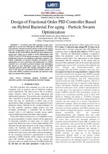
In order to establish and do the research on the kinematics model, we construct the reference coordinate system shown in Fig. 3. The coordinate system origin OXY is based on the center of the mechanical structure of the mobile platform, and the coordinate system origin OiXiYi is based on the center of the mechanical structure of each Mecanum wheel, any of the coordinate system conforms to the right-hand rule. In particular, the installation of the wheel body has deferent spin around (the left forward and right rear wheel is left-spin, the right forward and left rear wheel is right-spin, specifically, the angle between wheel axis and roller axis is 45°. it’s worth noting that the figure 1-a is observed from top to down of the omnidirectional mobile robot platform, as well as the oblique dashed lines drawn in each wheel is the contact line between roller surface and road surface. In Fig. 3, L is the distance that along Yaxis between the center of wheel and chassis, l is the distance that along X-axis between the center of wheel and chassis, and we assume that this mobile platform is running with the velocity (Vx Vy Wz) , at the same time,
© The Authors, published by EDP Sciences. This is an open access article distributed under the terms of the Creative Commons Attribution License 4.0 (http://creativecommons.org/licenses/by/4.0/).
MATEC Web of Conferences 95 , 08014 (2017)
DOI: 10.1051/ matecconf/20179508014
ICMME 2016 the wheel i is running with the line velocity Vi (angular velocity is Wi), ¢i is the offset angular of wheel i, R is the radius of each Mecanum wheel.
Y1
Y3
V1W
V3W
�1
Y
X1
�3
V y V3r
V1r
L
O
Y2
Vx
�z
V2W
X3
Zi X
Y4
Yi
V4W �4
V2r
optimization, it is also a kind of stochastic search algorithm based on population [6]. The DE Algorithm first proposed by Rain Storn et al. who came from California State University at Berkeley[7]. In view of the advantage of efficient, DE has drawn great attention of the relative scholars all over the world, which quickly became a hot research topic of optimizing computation.
�2
X4
X2
V4r
Oi
l
Xi
�i
�i
R Vir
r
G �E
�D
Figure 3. Moving principle of the omnidirectional mobile robot platform.
Figure 4. Diagram of omnidirectional moving of chassis.
According to the reference paper [5], it deduced the general kinematic mathematical model of the 4 Mecanum wheels omnidiretional mobile platform.
��1
�2 �3 �4 � � Ki � Vx Vy �z �
T
T
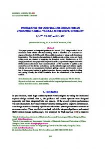
Initialization
3.1 Initialization
1 � ( Lcot� l ) � 1 � ( Lcot� l ) �� 1 Lcot� l � � 1 Lcot� l
The initial population is generated a size of Np randomly which include D dimension vector in each population, for example :
(2)
�z � � K f ��1 �2 �3 �4 � T
Selection
Figure 5. Operation flow of DE algorithm.
X i ,G � {X i1,G , X i2,G ,..., X iD,G }, i � 1, 2,..., Np
Thus, we transform the matrix formula (1), then get the forward kinematic model in formula (3). � Vx Vy
Recombination
(1)
in formula (1), the inverse kinematic matrix Ki is: �cot�
1 �cot� Ki � R �cot�
cot�
Mutation
T
(5)
In formula (5), the Np is a constant, every individual need make mutation, recombination and selection in turn, generations of population to be made evolution until computing over.
(3)
in formula (3), the forward kinematic matrix Kf is: � �
tan� tan� � � tan� � tan� � R Kf � 1 1 1 1 � 4 � 1 1 �1 �1
� Lcot� l Lcot� l Lcot� l Lcot� l
3.2 Mutation The mutant vector individual is computed by the follow fomula.
(4)
Vi ,G � X r1,G F ( X r 2,G X r 3,G ), r1, r 2, r 3 �{1, 2,..., Np}
(6)
In formula (6), iĮr1Įr2Įr3, F is a real constant factor to control the differential variation and F>0.The Vi,G is prepared for the next generation mutation vector, Xri,G is the current generation vector from different population.
From the above formulas, it shows that the velocity of omnidirectional mobile robot is decided by the cooperation from revolving velocity of the 4 Mecanum wheels. The detailed moving direction by different cooperation wheel speed of the chassis is shown in Fig. 4.
3.3 Recombination
3 Principle of DE
The recombination operation cross over each pair of the target vector Xr1,G and its corresponding mutant vector Vi,G for generating a trial vector Ui,G
Differential Evolution (DE) Algorithm is a simple and efficient method to solve the problem of global
2
MATEC Web of Conferences 95 , 08014 (2017)
DOI: 10.1051/ matecconf/20179508014
ICMME 2016 Ui ,G � {Ui1,G ,Ui2,G ,...,UiD,G }, i � 1, 2,..., Np
�� K *p � K p � � K *p �� * * �� Ki � Ki � � Ki � * * ��� K d � K d � � K d
(7)
In the basic version, DE employs the crossover defined as follows: �Vi ,Gj if (rand j [0,1] � CR) or � U i ,jG � � j � � X i ,G otherwise
j � jrand
, j � 1, 2,..., D (8)
(10)
4.2 Fitness function The target of optimizing PID controller is to improve the key performance indicators, such as stability, precision and highly response, so we indroduce overshoot(¥), rise time(tr) and accumulative error( ě |ek|) into the fitness function F as follows:
In formula (8), CR controls the fraction of parameter values copied from the mutant vector, CR is a userdefined real constant and randj is a random real constant, they are both between the range [0,1].
n
F � w1� w2tr w3 � | ek |
3.4 Selection
(11)
k �1
The DE algorithm uses greedy method that the best individuals are selected to replace parent individuals to generate new individual in general evolutionary strategies. The selection operation can be expressed as follows: � if ( f (U i ,G ) � f ( X i ,G )) �U X i ,G 1 � � i ,G � � X i ,G otherwise
in formula (11), the constant weight coefficient w1,w2,w3 are used for adjusting the influence of corresponding variables in system. 4.3 Optimizing flow
(9)
Step1: Define searching boundaries for PID parameters (Kp, Ki, Kd) by formula (10). Step 2: Define the population size Np, crossover probability CR, maximum number of iteration Gmax, then randomly generating initial population in searching boundaries. Step 3: According to the formula (6) make mutation for individuals in population. Step 4: According to the formula (8) make recombination for mutation individuals. Step 5: According to the formula (11) Compute the fitness values of every individual vector. Step 6: According to the formula (9) make selection for the next generation individuals. Step 7: If the number of iterations less than Gmax, repeat Step 2-7, otherwise end.
In formula (9), the fitness function f(x) is to evalutate the best result(individual).
4 Optimal controller design As we know, PID controller has been widely used in most industry control system, optimizing the PID parameters has been a considerable topic for the people [8]-[10]. In this paper, we use DE algorithm for optimizing and tuning parameters of PID controller in omnidirectional mobile robot. The principle of optimal PID controller designing based on DE algorithm is shown in Fig. 6. Fitness Function
r(t)
-
DE Algorithm
PID Controller
u(t)
Actuating Mechanism
y(t)
Figure 6. Principle of optimal PID controller design based on DE algorithm
4.1 Encoding Figure 7. Simulink model for omnidirectional mobile robot
In the PID controller, there are 3 parameters(Kp, Ki, Kd) to be optimized. DE algorithm using floating-point encoding method so that the 3 parameters could be directly served as a vector of individual. Then DE algorithm searching space is worked from the results of Ziegler-Nichols (Z-N) tuning method, thus making full use of the reasonable PID value of Z-N method.Assuming that K*p, K*i, K*d are the tuned value by Z-N method, ¢,£ are the scaling factors,we can define the boundry of searching by formula (10) :
5 Simulation and analysis 5.1 Simulation model In order to verify the correctness of the forward and inverse kinematics model,as well as the effectiveness of the optimized PID controller by DE algorithm, based on the actual conditions we set up an omnidirectional robot
3
MATEC Web of Conferences 95 , 08014 (2017)
DOI: 10.1051/ matecconf/20179508014
ICMME 2016 motion control platform by MATLAB simulink, please see Fig. 7. In Fig. 7, the ‘JoyInput’ model is a 3*1 column vector with sine signal, each element respectively corresponds to the input of direction X, Y, Wz; the ‘Inverse Kinematic’ model represents the matrix Ki in formula(2); ‘Random Load’ model generates the 3Nm torque random disturbance to the wheels; ‘Servo system’ model is the servo driver with space-vector PWM technique, each unit has a double-loop control system, furtherly the PID controller of speed loop is optimized by DE algorithm; the ‘Forward Kinematic’ model represents the matrix Kf in formula(4).
In Fig. 8, the convergence curve is the processing of DE algorithm. The Z-N PID parameters are Kp=31.2, Ki,= 5.3, Kd =1.2, after optimized by DE algorithm, the PID parameters are Kp=42.4, Ki,= 6.3, Kd =0.92. When we set the target sine signal with angular frequency ω=40rad/s, amplitude of three DOF Vx =0.2m/s, Vy =0.2m/s, Wz =0.2rad/s, the simulation results are shown as following Fig. 9. 5.3 Simulation results Given that any velocity loop PID controller of the 4 wheels is working in the same way, so we show the optimized results by an example here. From the simulation results of sine response, at the three DOF direction, the optimized PID controller by DE algorithm works with following error much less than the PID controller by Z-N tuned. It indicates the optimal controller design method is effective and control system has strong robustness, the results of simulation also show that the proposed inverse and forward kinematic are both correct and feasible.
5.2 Simulation parameters a) Mobile robot chassis parameters: L=1.0m, l=0.5m, transmission ratio i=100; b) Mecanum wheel parameters: roller offset angle ¢ =45e, wheel radius R=0.25m; c) PMSM parameters: rated speed wn=3000, torque Tn=20Nm; d) The fitness function weight coefficient: w1=10,w2=2,w3 =5; e) The DE algorthm population size Np=30, crossover probability CR=0.8, iterations max Gmax=50.
6 Conclusion In this paper, we analyzed the inverse and forward kinematics of omnidirectional mobile robot based on Mecanum wheel, then put forward the DE algorithm for optimizing PID controller of speed loop in servo system.Through MATLAB simulation platform, we bulit the simulaiton model of system, the results showed that the inverse and forward kinematics model are reasonable, DE algorithm optimization for the PID controller is better than traditional Z-N tuned. The DE algorithm can be implemented with ease and few parameters need to be tuned, which could be widely used in engineering practice.
Figure 8. Simulink model for omnidirectional mobile robot
References 1.
2. 3. 4.
5.
6. Figure 9. Sine response for omnidirectional mobile robot
4
Bashra K. O. ChaborAlwawi and Hubert Roth, etc, Mobile Robot Motion Planning and Multi Objective Optimization Using Improved Approach[J], International Journal of Mechanical Engineering and Robotic Research, 4.(Oct. 2015) Yaonan Wang, Robot intelligent control engineering.8.(Science Press, Beijing, 2004) Ilon BE, Directionally statble self propelled vehicle, P.3746112.( U.S., 1973) Dickerson SL, Lapin BD, Control of an omnidirectional robotic vehicle witch Mecanum wheels, IEEE proceedings of the Telesystems Conference, 323.( Atlanta, 1991) Zhou Liu, Hongtao Wu, Omnidirectional moiton analysis and simulation of Mobile mechanism with Mecanum wheel, Machine Design and Manufacture Engeering, 43-44, 40(05). (SEU Press, Nanjing, 2011) K. Price, Differential evolution a fast and simple numerical optimizer, 1996 Biennial Conference of
MATEC Web of Conferences 95 , 08014 (2017)
DOI: 10.1051/ matecconf/20179508014
ICMME 2016
7.
8.
the North American Fuzzy Information Processing Society, 524-527.(New York, 1996) R. Storn, K. Price, Differential evolution a simple and efficient adaptive scheme for global optimization over continuous spaces[C], Technical report International Computer Science Institute, 4147.(Berkley, 1995) Jinkun Liu, advanced PID control and MATLAB Simulink, 136. Electronics Industry Press, Beijing, (2002)
9.
Peng, Wang, et al. PID Parameter Tuning Based on Improved DE Algorithm and the Application, Journal of Chinese Society of Power Engineering. (2015) 10. Youxin Luo, and Xiaoyi Che, Tuning PID control parameters on hydraulic servo control system based on differential evolution algorithm, Logistics Systems and Intelligent Management 2010 International Conference on IEEE, 18611864.(2010)
5