2013 International Conference on Computer, Control, Informatics and Its Applications
Optimal Energy Control of DC Motor Speed Control: Comparative Study Hari Maghfiroh1, Ahmad Ataka2, Oyas Wahyunggoro3, A.I. Cahyadi4 Electrical Eng. And Information Tech.Dept., UGM Yogyakarta, Indonesia 1
[email protected],
[email protected],
[email protected],
[email protected] the rotational velocity with motor constant(Ke) shown in Equation (1).
Abstract—In this paper, the speed control problem of DC Motor is presented. Three different control algorithms, namely PID, Fuzzy, and LQR were designed and implemented. These controller were applied to the DC motor, and their performance and energy controller output were compared each other on the basis of unit-step response, disturbance rejection, and signal tracking. The aim of this comparative is to find the most optimal energy controller in the same task. The simulation results show that LQR is the most optimal energy controller compare with PID and Fuzzy.
(1) In SI units Kt is equal to Ke so it is assumed that Kt = Ke = K.
Keywords— PID, Fuzzy, LQR, Energy Control, DC motor
I.
Figure 1 DC Motor Model[10]
INTRODUCTION
The mathematical model of Fig. 1 is decomposed into two parts, electrical parts and mechanical parts. By using Kirchoff's law for electrical parts, and Newton's law for mechanics, we get Equation (2) and Equation (3). (2)
Electric motor is an actuator that is widely used in industry, for both DC motors and AC motors. However, both of them have different characteristics. DC motor has some advantages such as easy to control the speed and position [1][2][3]. DC motors are widely used as in steel rolling mills, electric trains, electric vehicles, and robotic actuators [2][4]. The research in speed control of DC motor has been done by a lot researchers based on performance viewpoint, as in [5][6][7][8], so in this paper, energy viewpoint will used. The main contribution of this paper is to determine which controller is the most energy efficient on the same task. Because energy is an important issue today, and according to [9], the electric motor is one of the appliances that consume considerable electrical energy. Some methods to be compared in this paper are: PID (state of the art of classical control), Fuzzy Logic (one of the best of intelligent control), and Linier Quadratic Regulator (LQR) that is the state of the art of optimal control. Experiment was done for the unit step response, disturbance rejection and tracking where the performance and energy controller were observed based on MATLAB simulink platform. This paper is organized as follows. In section II, present the mathematical model of the DC motor. In section III, Controllers are designed. In section IV, MATLAB simulation results are presented and discussed. Finally the conclusion is in section V. II.
(3) Using Laplace Transforms, Equation (2) and (3) becomes Equation (4) and (5) respectively. (4) (5) By eliminating I(s), the open loop transfer function with rotational speed as output and voltage as input is shown in Equation (6). (6) In state-space form, Equation (4) and (5) can be expressed by choosing the rotational speed and electrical current as the state variables and the voltage as an input, Equation (7). The output is chosen to be the rotational speed, Equation (8). 0
1
(8)
According S.J. Chapman [11], there are three methods that are widely used in the DC motor speed control, field resistance control, armature voltage control, and armature resistant control. In this study, armature voltage control was used so that a review of energy can be done by measuring the
DC MOTOR MODEL
DC motor model is shown in Fig. 1. The motor torque (T) is connected to the motor armature by an armature constant (Kt) whiles the back electromotive force (EMF) is related to
c 978-1-4799-1078-6/13/$31.00 2013 IEEE
0
(7)
89
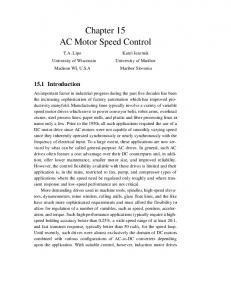
membership limit (NB, NS, ZE, PS, PB) for both input and output. Fig. 2 shows the membership function of error (the first input), the second input (ce) had the same shape, while Fig. 3 shows the membership function of output. The rules were designed as in Table 2.
applied voltage to a DC motor. The instantaneous power (p) is proportional to V2 as . (9) Where c is constant that comes from the impedance of the motor and V is controller output or voltage input to the motor. The total energy (w) at time t, can be calculated as (10) = Performance indices are calculated and used to evaluate the performance of the system. In this paper, ISE (integral square error), Equation (11), and energy (w) were used. Because we use the same DC motor, so in energy comparative we just compare value. (11) Where e, error, that is the difference between set-point and system output. For this research we refer the physical parameter from [10] as follow:
Figure 2 Input Membership
Table 1 DC Motor Physical Parameter
Symbol J b K R L V
Quantity Moment inertia of the motor Damping ratio of the mechanical system Electromotive Force Constant Electric resistance Electric inductance Source Voltage Position of shaft III.
Value 0.01 kg.m2/s2 0.1 Nms Figure 3 Output Membership
0.01 Nm/A
Table 2 Matrix Rules
1Ω 0.5 H Input Output
CONTROLLER DESIGN
A. Proportional-Integral-Derivative(PID) Controller PID controller is the most extensively control algorithm used in industry control scheme [12]. PID algorithm is widely used because it is simple and easy to apply [13][14][15][16]. Performance is determined by the determination of PID parameter that is KP, KI, and KD. In this paper, PID parallel structure was used as Equation (12) and the parameters were determined using MATLAB automatic tuning. y t
KP e t
KI
e t dt
KD
CE\E
NB
NS
ZE
PS
PB
PB
NB
NS
ZE
PS
PB
PS
NS
ZE
ZE
ZE
PS
ZE
NB
ZE
ZE
ZE
PB
NS
NS
ZE
ZE
ZE
PS
NB
NB
NS
ZE
PS
PB
C. Linier Quadratic Regulator(LQR) Controller LQR is one of the optimal control techniques which take into account the states of the dynamical system and control input to make optimal control decisions. This is simple as well as robust [21]. Suppose the state equation of the linier timeinvariant system is: (13) (14)
(12)
B. Fuzzy Logic Controller Numerous successful applications of fuzzy logic controller in industry make this branch of intelligent control so many credits and respect in control community[17]. The main advantage of this method is, it is not require precise mathematical models of plant[18][19][20]. The controller only needs the output values from sensors along with the bounds on the control signal which can be applied to the system. The fuzzy logic controller that used is Mamdani type. This controller had two inputs, namely error (e) and change of error (ce), and one output that was controller signal. Triangular membership functions were used in the design with five
The state feedback control u(t) = -KLQR x(t) leads to (t) (15) where KLQR is derived from minimization of cost function as shown in (16). (16) Q and R denote the weighting matrix of states variable and input variable where Q = QT ≥ 0(positive semi-definite) and R = RT > 0 (positive definite). The LQR gain vector KLQR is given by (17)
90
than Fuzzy. From ISE value, Table 4, LQR has the smallest value. Concerning the disturbance rejection, LQR is the best performance because of no oscillation when disturbance happen.
Where P(t) is a positive definite symmetric constant matrix obtained from the solution of matrix algebraic riccatti equation(ARE) as in Equation(18). Q and R matrix were determined using experiment method, while KLQR was determined using MATLAB command KLQR = lqr(A, B, Q, R). 0 IV.
(18)
SIMULATION RESULTS
A. Unit Step Response Fig. 4 shows the performance comparison in unit step response. LQR controller has the fastest response time, while Fuzzy has the slowest response. PID has fast response too, but it has too much overshoot. LQR doesn’t have an overshoot while Fuzzy has a small overshoot. As shown in Table 3, LQR has the lowest value of ISE. Based on the performance criteria, LQR has the best rank in unit step response. The next step is comparison in energy controller criteria. Fig. 5 shows the energy controller comparison in unit step response. At starting time PID has the highest energy while Fuzzy has the lowest, and after 7 s (sampling time is 0.01 s), PID and Fuzzy have the same output energy. LQR has the highest energy in starting time too, but it’s still lower than PID and Fuzzy needed in normal operation time (after 7 s). As shown in Table 3, LQR has the lowest value. Based on energy controller criteria, LQR is the most efficient in unit step response and also with the best response.
Figure 5 Energy Controller Comparison in Unit-step Response
Based on energy controller criteria, Fig. 7, at starting time PID has the highest energy while Fuzzy has the lowest. When disturbance happen, LQR need a small energy to cover it, while PID and Fuzzy need a lot. From Table 4, LQR has the smallest value of overall energy controller. PID has the highest value, because we also count the starting time energy consumption, but if we concern to the energy consumption in the disturbance rejection, Fig. 7, we can see Fuzzy consume more energy than PID in the disturbance rejection.
Table 3 ISE and w in Unit-step Response
Controller
ISE
PID Fuzzy LQR
30.635 133.471 20.756
Table 4 ISE and w in Disturbance Rejection
98564.53 73215.06 955.691
Controller
ISE
PID Fuzzy LQR
30.721 133.997 20.756
148708.29 12346.995 1460.020
Figure 4 Performance Comparison in Unit-step Response
B. Disturbance Rejection Fig. 6 shows the performance comparison in disturbance rejection, in which LQR controller has very small oscillation when the disturbances enter the system, while Fuzzy has the higher amplitude oscillation. PID has the oscillation but the amplitude is smaller than Fuzzy, and the settling time is faster
Figure 6 Performance Comparison in Disturbance Rejection
91
Figure 8 Performance Comparison in Signal Tracking
Figure 7 Energy Controller Comparison in Disturbance Rejection
C. Signal Tracking The last experiment is tracking. Fig. 8 shows the performance comparison in tracking. It is shown that PID can track the signal although overshoot happen, Fuzzy has the worst result in tracking, and LQR can track the signal well with no overshoot. Based on Table 5, LQR has the smallest ISE so it is concluded that LQR has the best performance in signal tracking. Comparing in energy controller criteria, Fig. 9 shows that LQR has the smallest controller energy signal. PID has higher energy when the speed increased than decreased. Fuzzy consume higher energy than LQR but lower than PID. It also has the smallest value of as in Table 5. Thus, LQR is the most efficient controller in signal tracking.
Figure 9 Energy Controller Comparison in Signal Tracking
Table 5 ISE and w in Signal Tracking
Controller
ISE
PID Fuzzy LQR
49.984 234.564 41.507 I.
REFERENCES [1]A. Faramarzi and K. Sabahi, “Recurrent Fuzzy Neural Network for DCmotor control,” in 2011 Fifth International Conference on Genetic and Evolutionary Computing, 2011, pp. 93–96. [2]S. Pavankumar, S. Krishnaveni, Y. B. Venugopal, and Y. S. K. Babu, “A Neuro-Fuzzy Based Speed Control of Separately Excited DC Motor,” in 2010 International Conference on Computational Intelligence and Communication Networks, 2010, pp. 93–98. [3]W. Yan, D. Wang, P. Jia, and W. Li, “The PWM speed regulation of DC motor based on intelligent control,” vol. 00, no. 2011, 2012. [4]A. Hughes, Electric Motor and Drives, 3rd ed. Great Britain: Elsevier Ltd., 2006. [5]A. Balestrino, A. Caiti, V. Calabró, E. Crisostomi, and A. Landi, “From Basic to Advanced PI Controllers : A Complexity vs . Performance Comparison,” in Advances in PID Control, no. 1, V. D. Yurkevich, Ed. Rijeka, Croatia: InTech, 1922, pp. 85–100. [6]P. H. B. Kazemian, “Intelligent Fuzzy PID Controller,” in Application of Fuzzy Control, Genetic Algoritms and Neural Nerworks, vol. 2, R.Lowen and A.Verschoren, Eds. Springer, 2008, pp. 241–260. [7]M. Arrofiq and N. Saad, “A PLC-based Self-tuning PI-Fuzzy Controller for Linear and Non-linear Drives Control,” no. PECon 08, pp. 701– 706, 2008. [8]B. Nagaraj, S. Subha, and B. Rampriya, “Tuning Algorithms for PID Controller Using Soft Computing Techniques,” vol. 8, no. 4, pp. 278–281, 2008. [9]J. De Oliveira and A. Nied, “Study on the Energy Efficiency of Soft Starting of an Induction Motor with Torque Control,” in Advances in Motor Torque Control, 1st ed., vol. 2035, M. Ahmad, Ed. Rijeka, Croatia: InTec h, 2010, pp. 33–46.
70920.238 39797.913 679.780
CONCLUSIONS
Three control algorithms for the DC motor speed control have been designed and implemented. Their performances have been compared on the basis of unit-step response, disturbance rejection and signal tracking. Performance and control energy requirement were used as the comparison criteria, but the most concern was in energy. Experiment results show that LQR is the most optimal energy controller compare with PID and Fuzzy. ACKNOWLEDGMENT The authors would like to express the sincere appreciation to Electrical Engineering and Information Technology Department, Universitas Gadjah Mada (UGM) for providing research facility. The Ministry of Education and Culture, Republic of Indonesia for their Intellectual Social Responsibility (ISR) in Beasiswa Unggulan Fast-track.
92
[10]F. Valdez, P. Melin, and O. Castillo, “Particle Swarm Optimization for Designing an Optimal Fuzzy Logic Controller of a DC Motor,” pp. 3–8, 2012. [11]S. J. Chapman, Electric Mechinery Fundamentals, 4th ed. Singapore: Mc Graw Hill, 2005. [12]M. Araki, “PID Control,” PID control in Control systems, Robotics and Automation, vol. II, no. Encyclopedia of Life Support Systems (EOLSS), Developed under the Auspices of the UNESCO, Eolss Publishers, Oxford,UK., 1989. [13]C. Karray, Fakhreddine O.;De Silva, “Expert parameter tuning of DC motor controller,” in Soft Computing and Intelligent Systems Design, Harlow, England: Pearson Education, 2004, pp. 476–496. [14]K. S. Tang, K. F. Man, S. Member, G. Chen, and S. Kwong, “An Optimal Fuzzy PID Controller,” vol. 48, no. 4, pp. 757–765, 2001. [15]J. Rusnak, “New techniques for PID Controller Design,” no. Chien 1988, pp. 903–908, 2003.
[16]H. Liu, “Algorithm of Fuzzy PID Parameters Self tuning And its realization in PLC System,” in International Conference on Computational Aspect of Social Networks, 2010, no. 1, pp. 561–564. [17]S. Bogdan and D. Krapinec, “Sensitivity-based Self-learning Fuzzy Logic Controller as a PLC Super Block.” [18]J. Xiao, “Speed Control System Based on Improved Fuzzy-PID hybrid Control for Direct Current Motor,” pp. 392–395, 2010. [19]M. Hamza, Q. Zahid, F. Tahir, Z. Khalid, and R. Rehman, “Real-Time Control of an Inverted Pendulum: A Comparative Study,” in 2011 Frontier of Information Technology, 2011, no. 2, pp. 183–188. [20]M. M. Shaker, “Design and Implementation of Fuzzy Logic system for DC motor Speed Control,” pp. 123–130, 2010. [21]L. B. Prasad and B. Tyagi, “Modelling & Simulation for Optimal Control of Nonlinear Inverted Pendulum Dynamical System using PID Controller & LQR,” 2012. [22]K. Ogata, Modern Control Engineering, 5th ed. New Jersey: Pearson Education,Inc., 2010.
93