This paper describes the speed control of dc motor using conventional .... optimal
design of fuzzy PID controllers,” IEEE Transaction of fuzzy systems, vol. 7, no.
International Journal of Information and Computation Technology. ISSN 0974-2239 Volume 3, Number 3 (2013), pp. 181-188 © International Research Publications House http://www. irphouse.com /ijict.htm
Simulation of Optimal Speed Control for a DC Motor Using Conventional PID Controller and Fuzzy Logic Controller Ritu Soni1, DBV Singh2, Pramod Pandey3 and Priyanka Sharma4 1, 4
Department of Electronics and Instrumentation Engineering, Department of Electronics and Instrumentation Engineering, 3 Department of Electronics and Instrumentation Engineering, ITM University, Gwalior (M.P). 2
Abstract This paper describes the speed control of dc motor using conventional PID controller and Fuzzy Logic controller. Due to the simplicity in operation, conventional PID controllers were used as a control strategy for various industrial processes from many years. They used mathematical models to control the plant for different process control applications. Fuzzy logic based control systems were introduced by Lotfi Zadeh to optimize the process control parameters in better way. In this paper, the implementation of DC motor control strategy with the help of PID controller and then optimized with the help of fuzzy logic controller. The fuzzy logic control strategy shows the improvement in various control parameters like maximum overshoot, settling time for the DC motor control as compared with PID control strategy. The controller is modeled in MATLAB environment, the simulation results shows that the proposed controller gives better performance and less settling time when compared with the traditional PID controller. Keywords: Fuzzy logic controller, PID controller, DC motor.
1. Introduction Because of their high reliabilities, flexibilities and low costs, DC motors are widely used in industrial applications, robot manipulators and home appliances where speed and position control of motor are required. PID controllers are commonly used for motor control applications because of their simple structures and intuitionally comprehensible control algorithms. Controller parameters are generally tuned using
182
Ritu Soni et al
hand-tuning or Ziegler-Nichols frequency response method. Both of these methods have successful results but long time and effort are required to obtain a satisfactory system response. Ziegler-Nichols frequency response method is usually used to adjust the parameters of the PID controllers. However, it is needed to get the system into the oscillation mode to realize the tuning procedure. But it’s not always possible to get most of the technological plants into oscillation. Fuzzy logic control (FLC) is one of the most successful applications of fuzzy set theory, introduced by L.A Zadeh in 1973 and applied (Mamdani 1974) in an attempt to control system that are structurally difficult to model. Since then, FLC has been an extremely active and fruitful research area with many industrial applications reported [1].In the last three decades, FLC has evolved as an alternative or complementary to the conventional control strategies in various engineering areas. Analysis and control of complex, nonlinear and/or time-varying systems is a challenging task using conventional methods because of uncertainties. Fuzzy set theory [2] which led to a new control method called Fuzzy Control which is able to cope with system uncertainties. One of the most important advantages of fuzzy control is that it can be successfully applied to control nonlinear complex systems using an operator experiences or control engineering knowledge without any mathematical model of the plant [3],[4].
2. PID Controller The PID controller is used to improve the dynamic response and reduce the steadystate error. The general equation of PID controller is: ( )= ( )– + + (1) Where, Kp = proportional gain, Ki = Integral gain, Kd = Derivative gain. The variable E(S) represents the tracking error which is the difference between the desired input value and the actual output. This error signal will be sent to the PID controller and both the derivative and the integral of this error signal are computed by the controller. The system performance can be evaluated by performance criteria parameters. These performance criteria in the time domain include the overshoot Mp, rise time tr, settling time ts and steady-state error Es.
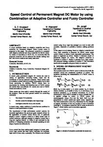
3. Plant Model The speed of a DC motor is directly proportional to the applied voltage to it and its torque is proportional to the motor current:T = K I For separately exited DC motor, the back emf is proportional to the rotational velocity: Vemf = K wm = K dθ/dt Speed control can be achieved by variable battery tappings, variable supply voltage, resistors or electronic controls. The equivalent circuit of dc motor is shown in Fig 1. The armature circuit consist of a resistance (Ra) connected in
Simulation of Optimal Speed Control for a DC Motor Using Conventional PID
183
series with an inductance (La), and a voltage source (Vemf) representing the back emf induced in the armature during rotation. [Ogata, 1998 and 2002]. The DC motor equations based on Newton's law combined with Kirchhoff's law: J d2θ/dt2 + b dθ/dt = K I (1); L di/dt + Ri = V- K dθ/dt (2) V = applied voltage (V), R = electrical resistance of armature circuit (Ω), L= electrical inductance of armature circuit (H), J = Inertial load (kgm2/s2),Vemf = back emf voltage (V), B = damping constant (Nm.S) Using the Laplace transform, equations (1) and (4) can be written as: J s2 θ(s) + b s θ(s) = K I(s) (3); L s I(s) + R I(s) = V(s) – K s θ(s) (4) The transfer function is given by ( ) ( )= = [{( (5) )( ) }] ( ) Nominal values of desired DC motor model Maximum speed of the motor (N) = 1200 r.p.m., Supply voltage (V) = 240 V, Back emf (E) = 230.3V, Armature current (i) = 16.2 A, Power (P) = 3731 W or 5 HP, Field resistance (Rf ) = 240 Ω, Armature resistance (R) = 0.6 Ω Mutual inductance (L) = 1.8 H, Motor inertia (J) = 1 Kg.m2, Motor torque (T) = 29.2 N. m, Motor torque constant (K) = 1.88 N. m/A, Damping coefficient (b) = 0.24 N. m. s.
1 LS R
K
1 JS b
1 S
K
Fig. 1: Equivalent representation of DC motor.
Fig. 2: A closed- loop system that representing the DC motor.
4. Fuzzy Lozic Controller Fuzzy logic is a method of rule-based decision making used for expert systems and process control that emulates the rule-of-thumb thought process used by human beings. The basis of fuzzy logic is fuzzy set theory which was developed by Lotfi Zadeh in the 1960s. Fuzzy set theory differs from traditional Boolean (or two-valued) set theory in that partial membership in a set is allowed. Traditional Boolean set theory is twovalued in the sense that a member belongs to a set or does not and is represented by 1 or 0, respectively. Fuzzy set theory allows for partial membership, or a degree of membership, which might be any value along the continuum of 0 to 1. A linguistic term can be defined quantitatively by a type of fuzzy set known as a membership function. The membership function specifically defines degrees of membership based on a property such as temperature or pressure. With membership functions defined for
184
Ritu Soni et al
controller or expert system inputs and outputs, the formulation of a rule base of IFTHEN type conditional rules is done. Such a rule base and the corresponding membership functions are employed to analyze controller inputs and determine controller outputs by the process of fuzzy logic inference. By defining such a fuzzy controller, process control can be implemented quickly and easily. Many such systems are difficult or impossible to model mathematically, which is required for the design of most traditional control algorithms. In addition, many processes that might or might not be modeled mathematically are too complex or nonlinear to be controlled with traditional strategies. However, if a control strategy can be described qualitatively by an expert, fuzzy logic can be used to define a controller that emulates the heuristic rule-of-thumb strategies of the expert. Therefore, fuzzy logic can be used to control a process that a human can control manually with expertise gained from experience. The linguistic control rules that a human expert can describe in an intuitive and general manner can be directly translated to a rule base for a fuzzy logic controller.
Fig. 3: Triangular input membership function for input (error).
Fig. 4: Triangular input membership function for input (change in error).
Fig. 5: Triangular input membership function for output (position).
Simulation of Optimal Speed Control for a DC Motor Using Conventional PID Table 1: IF-THEN rule base for fuzzy logic control. E CE LN MN SN Z SP MP LP
LN
MN
SN
Z
SP
MP
LP
LN LN LN LN MN SN Z
LN LN LN MN SN Z SP
LN LN MN SN Z SP MP
LN MN SN Z SP MP LP
MN SN Z SP MP LP LP
SN Z SP MP LP LP LP
Z SP MP LP LP LP LP
5. Simulation and Results
Fig. 7: Simulation dia. for PID controller
Fig. 8: Simulation dia. for Fuzzy controller
Fig. 9: Response of PID controller tuned by Z-N method
Fig. 10: Response of Fuzzy Logic controller.
185
186
Ritu Soni et al Table 2: Comparison of Maximum overshoot, settling time and steady state error for PID and FLC controllers. S. No. controller 1 2
Max. overshoot Z-N PID 48.5% controller Fuzzy logic 0 controller
Settling Time 21.5 sec.
SS Error
14.41 sec.
0.2%
1.4%
6. Conclusion In this paper a DC motor is controlled using fuzzy logic and PID controller. A mathematical model to control the DC motor is developed and the motor is controlled using conventional PID controller. The simulation results so obtained show that the PID controller gives high overshoot and settling time. Hence, fuzzy logic controller design was proposed and implemented using the principles of artificial intelligence. The fuzzy logic control is implemented and the response is compared with conventional PID controller. The fuzzy logic control shows a better control of motor parameters as compared with the conventional PID controller.
References [1]
[2] [3]
[4] [5]
[6]
[7]
H.X.Li and S.K.Tso, "Quantitative design and analysis of Fuzzy ProportionalIntegral- Derivative Control- a Step Towards Autotuning", International journal of system science, Vol.31, No.5, 2000, pp.545-553. Zadeh, L. A., Fuzzy Sets. Information and Control, 8, 338-353, 1965. Assilian, S. and Mamdani, E.H., An Experiment in Linguistic Synthesis with a Fuzzy Logic Controller. International Journal of Man-Machine Studies, 7(1), 1-13, 1974. Kickert, W. J. M. and van Nauta Lemke, H. R., Application of a Fuzzy Controller in a Warm Water Plant. Automatica, 12(4), 301-308, 1976. B.G. Hu, G.K.I Mann and R.G Gosine, “New methodology for analytical and optimal design of fuzzy PID controllers,” IEEE Transaction of fuzzy systems, vol. 7, no. 5, pp. 521-539, 1999 Han-Xiong Li,Lei Zhang, Kai-Yuan Cai, And Guanrong Chen,“ An Improved Robust Fuzzy-PID Controller With Optimal Fuzzy Reasoning,” IEEE Transactions On Systems, Man, And Cybernetics Part B: Cybernetics, Vol. 35, No. 6, December 2005; 1283-1292 G. Haung and S. Lee, “PC based PID speed control in DC motor,” IEEE Conf. SALIP-2008, pp. 400- 408, 2008.
Simulation of Optimal Speed Control for a DC Motor Using Conventional PID [8]
187
Zhen-Yu Zhao, Masayoshi Tomizuka, Satoru Isaka, “Fuzzy gain scheduling of PID controllers,” IEEE transactions on systems, man and cybernetics, vol. 23, no. 5, September/October 1993; 1392-1398. [9] Cheong, F., Lai, R., Constraining the Optimization of a Fuzzy Logic Controller Using an Enhanced Genetic Algorithm, IEEE Transactions on Systems, Man and Cybernetics-Part B: Cybernetics, Vol 30, No.1, Feb 2000. [10] Arpit Goel, Ankit Uniyal, Anurag Bahuguna, Rituraj S. Patwal and Husain Ahmed “Performance [11] Comparison Of PID and Fuzzy Logic Controller Using Different Defuzzification Techniques for Positioning Control Of DC Motors” Journal of Information Systems and Communication ISSN: 0976-8742 & E-ISSN: 09768750, Volume 3, Issue 1, 2012, pp.-235-238.
188
Ritu Soni et al